1. Introduction
The germicidal effect of ultraviolet radiation on biological objects (cells, bacteria, viruses, etc.) is well known. It is usually associated with radiation in the wavelength range of 200–300 nm. If we consider the cell as an elementary structural unit of living organisms, then we can say that this radiation is capable of leading to irreversible damage in the cell due to photochemical reactions. Such experiments began to be performed in the first half of the 20th century [
1,
2,
3]. More details about these studies can be found in [
4,
5]. As a rule, this is primarily understood as a violation of the structures of DNA and RNA, as well as proteins and other components of the cell or virus [
6,
7,
8,
9,
10]. It can be said that the universal nature of the action of ultraviolet radiation on microorganisms leads to the loss of their ability to conduct normal life and reproduce, which ultimately leads to their death. Surface doses of germicidal radiation required for inactivation of different microorganisms are presented in [
11,
12].
The germicidal effect of light makes it possible to effectively use UV emitters of the appropriate range for sterilizing water [
7] and air [
5,
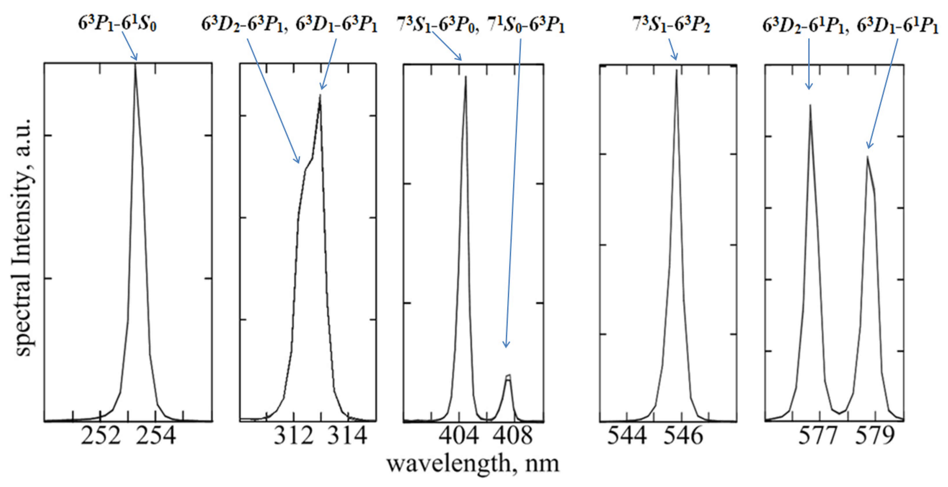
8]. Low-pressure mercury lamps are most commonly used as the sources. The ozone-free version of these lamps is due to the radiation of the resonant transition of the 6
3P1-6
1S0 mercury atom with a wavelength of ~253.7 nm. The version of radiation on the two main resonance lines of the mercury atom, including the
61P1-
61S0 transition with a wavelength of ~185 nm, supposes that the appearance of ozone-ozone begins to form in an oxygen-containing gas (for example, air) [
5,
13,
14] when exposed to such deep UV radiation. More information about this is in
Section 6.2. In some cases, it may be preferable to use broadband radiation sources, such as high-pressure mercury lamps and repetitively pulsed xenon lamps [
10] as well as excimer (exciplex) lamps [
5]. Excimer lamps based on XeBr molecules (~282-nm emission band), XeI (~253 nm), and KrCl (~222 nm) as well as on emission bands of homonuclear Cl
2 molecules (~259 nm) and Br
2 (~289 nm) can be used as a light source of germicidal range.
When disinfecting indoor air, sources of UV light can be used open, i.e., the processing of the premises is carried out in the absence of people. According to this principle, germicidal sterilization devices usually work in air conditioning and ventilation systems where there are no people in the irradiation zone. When processing air directly in rooms with people in it, UV light sources are enclosed in a housing in which the germicidal radiation is blocked inside the cavity volume [
7]. A germicidal air purifier also includes a power supply for the lamp (or lamp system) and at least one fan to pump air through the irradiated cavity and pre-filtering system.
UV air cleaners are widely used for air disinfection. A large number of devices for air disinfection of different manufacturers are known, differing in design details and control system [
11]. A large number of bactericidal emitters built into ventilation and air conditioning systems are known.
2. Problem of the Effective Use of Germicidal Radiation in UV Air Purifiers
A significant disadvantage of using UV cleaners for air disinfection is that only a negligible fraction of light energy is actually spent on suppressing the vital activity and reproduction of microorganisms, and the bulk of the radiation is absorbed by the surface of the emitter body (or by the walls of the room in the case of open emitters). This is due to the fact that the absorption length of germicidal radiation in the air is orders of magnitude higher than the dimensions of both the disinfection device cavity and the transverse dimensions of air ducts in air conditioning and ventilation systems. Thus, in order to increase the efficiency of the air purifier, it is advisable to maximize the irradiation produced by the lamp. It is possible to advance in this direction if most of the inner surface of the cavity is highly reflective for UV radiation. For these purposes, mirror-reflective stainless steel or aluminum is most often used. The increase in irradiation, according to [
15], is about 1.3 for the reflective surface of the emitter housing made of stainless steel and up to 2 times for the reflecting surface of the emitter housing made of polished aluminum. These values are achieved due to a high reflection coefficient of UV radiation from the materials.
Furthermore, mirror-reflective inner surfaces of the cavity in general cannot ensure uniformity or symmetry of the radiation field inside the cavity due to the inevitable presence of glare and shadow zones produced by specular reflection. The efficiency of the germicidal action of the air purifier may be limited by less irradiated “shadow” zones if a considerable part of circulating air will pass through these zones.
Additionally, in a mirror-reflective cylindrical cavity with a radiation source placed in the axis the radiation will return to the source after one reflection, violating thermal and radiation conditions of the source operation.
3. Benefits of Using Diffuse Reflective Material
A sharp increase in the efficiency of using germicidal radiation can be realized when using a diffusely reflecting inner surface of the irradiated housing or a reflector with a high reflection coefficient of 95–98% [
9]. In this case, the entire inner surface of the reflector is made of a material that diffusely reflects radiation with an effective reflectance of 95% or higher. This makes it possible to multiply the radiation intensity inside the housing, compared to that of UV air purifiers with an inner surface made of specularly reflecting materials (stainless steel, aluminum). Additionally, in the case of diffuse reflection, a significantly higher uniformity of radiation is provided [
16].
Polytetrafluoroethylene (PTFE, teflon) can be considered as an efficient diffusely reflecting material. It has a high coefficient of diffuse reflection in the bactericidal spectral region, above 90–93% depending on a thickness of ~2–4 mm. Expanded PTFE (ePTFE) can be considered as a material with a diffuse reflection coefficient of UV radiation >95%. This is PTFE material with numerous tiny pores quite evenly distributed in it, usually occupying 60–70% of the volume of this material [
9]. Light scattering at multiple PTFE–air boundaries with an appropriate material thickness provides an effective diffuse reflectance of >95%. Here it is fundamentally important that pure PTFE practically does not absorb UV radiation of the bactericidal range (as well as air). Specialized materials such as Spectralon by Labsphere, Inc. with a reflectance of more than 95% for a wavelength of ~250 nm may also be of interest [
17]. Coatings based on particles that are transparent to radiation and distributed in a transparent binder structure (matrix) with a different refractive index also have a highly diffuse reflectance in this region of the spectrum. An example of such materials is the barium sulfate coating Spectraflect. The material was also developed by Labsphere, Inc. [
17]. With a thickness of 0.5 mm, it provides a diffuse reflectance of at least 93% for a wavelength of ~260 nm. When choosing a material, it is important to take into account its technological and cost parameters.
It should be pointed out that the reflection becomes essentially diffuse also in the case of a metal surface with sufficiently small-scale irregularities (for example, reflection from a rough aluminum surface is essentially diffuse). However, in this case, the effective coefficient of diffuse reflection from a rough aluminum surface will not be greater than the coefficient of reflection from a smooth mirror surface of aluminum. Accordingly, the use of a matted (rough) aluminum inner surface of the emitter housing does not provide a significant advantage in germicidal efficiency.
In the following sections, using a model cylindrical cavity of a germicidal air purifier with an amalgam mercury lamp mounted on an axis, we consider theoretically and experimentally the amplification effect of the radiation flux inside the cavity and the benefits from radiation flux amplification and symmetrization by using walls of highly diffuse reflection coefficient materials. Partly parallel consideration of the design of a UV-LED-based bactericidal air purifier is described in [
18]. Our consideration differed significantly in the type of radiation source used, as well as in the performance analysis of inlet and outlet air ports combining high throughput for the air flow with the ability to reflect UV radiation back into the illuminated volume.
4. Radiation Flux Amplification in a Cylindrical Cavity with Highly Diffuse Reflective Walls
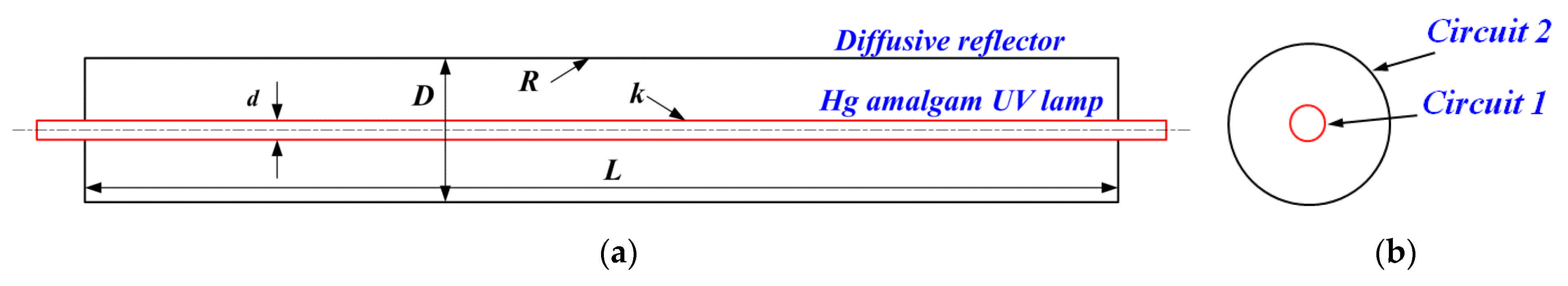
In this section, the irradiation of the walls of a cylindrical diffusely reflecting cavity is calculated by being irradiated with a cylindrical Lambertian radiation source located on the axis (such as a low-pressure Hg vapor quartz lamp). We took into account multiple reflections from the walls of the cylindrical reflector and from the surface of the Lambertian emitter. Let a cylindrical cavity of length
L and diameter
D have walls with an ideal diffuse reflection coefficient
R. A cylindrical Lambertian emitter with a diameter
d is located on the axis of the cavity (
Figure 1a). Edge effects were not taken into account. The end surfaces of the cylindrical cavity were treated as being perfectly reflecting mirrors. In this case, the irradiation of the cylindrical surfaces of both the emitter and the reflector along the length
L will be uniform. Only radiation fluxes in one cross section were of interest. Therefore, we considered a 2D cross section with a source of bactericidal radiation located in the center: We needed to find a solution of a two-dimensional cylindrically symmetric problem (
Figure 1b).
The central cylindrical surface (
Figure 1b, circuit 1) uniformly emits light with an energy flux
P (W) in a certain wavelength interval. Then its emissivity is
E =
P/(π
dL). By emissivity we mean the power of the radiation flux per unit surface area. In the cylindrical case it was convenient to operate with linear values:
PL =
P/
L and
EL =
PL/(π
d). Then, for the linear brightness we can write
BL =
EL/2. Indeed, in order to calculate the linear emissivity, knowing the linear brightness of the Lambertian source, it is sufficient to calculate the integral:
For linear irradiation of the cavity walls (
Figure 1b, circuit 2) without taking into account multiple reflections, we can write
IL =
ELd/
D: The entire flux from the central cylindrical emitter fell on the wall of the cylindrical diffuse reflector. Let us find the light flux on the surface of the reflector after a single reflection, assuming that there is no obstacle in the form of a Lambertian emitter on the axis (if there is no circuit 1). After a single reflection, the surface of the diffuse reflector can be considered a Lambertian source with a linear emissivity
ILR and a corresponding linear brightness
ILR/2 =
BLR. The factor
R < 1 takes into account that the radiation incident on the reflector is partially reflected. To calculate the flux of singly reflected radiation onto the reflector wall in the absence of an obstacle on the axis, one should calculate the integral:
In reality, when observing from any point of the reflector, part of the cylindrical surface is not visible, since it is shaded by the surface of the Lambert emitter (circuit 1), which, on the one hand, does not transmit radiation and, on the other hand, in addition to its own radiation, it re-radiates part of the received radiation. Upon further consideration, the radiation is reflected or re-radiated many times.
To correctly account for this effect, we will make some more assumptions. Let the source surface diffusely reflect the incident radiation with the exception of a certain fraction k, which it absorbed (k is the absorption coefficient at the emitting surface of the lamp). If we talk about the radiation of the resonant transition of the mercury atom λ = 253.7 nm, the emitting surface absorbs all the received radiation, since the absorption cross section of resonance radiation by mercury atoms is high. Nevertheless, most of the atoms excited in the absorption process almost immediately re-emit quant in an arbitrary direction. Some of the re-emitted quanta are returned to the cavity between the emitter (circuit 1) and the reflector (circuit 2). The rest of the quanta are reabsorbed and re-emitted later or die in emission-free energy transitions. The coefficient k takes into account the combination of the discussed processes.
For simplicity of calculations, we assume that d << D: The diameter of the emitter is much smaller than the diameter of the reflector. In order to determine the emissivity of the emitter surface in a single reflected light, we determine the irradiation on the emitter surface created by the reflector. It is easy to verify that it is also equal to the ILR, that is, the corresponding emissivity of the emitter surface in the once reflected and re-emitted light will be ILR(1 − k) with the corresponding linear brightness ILR(1 − k)/2 = BLR(1 − k).
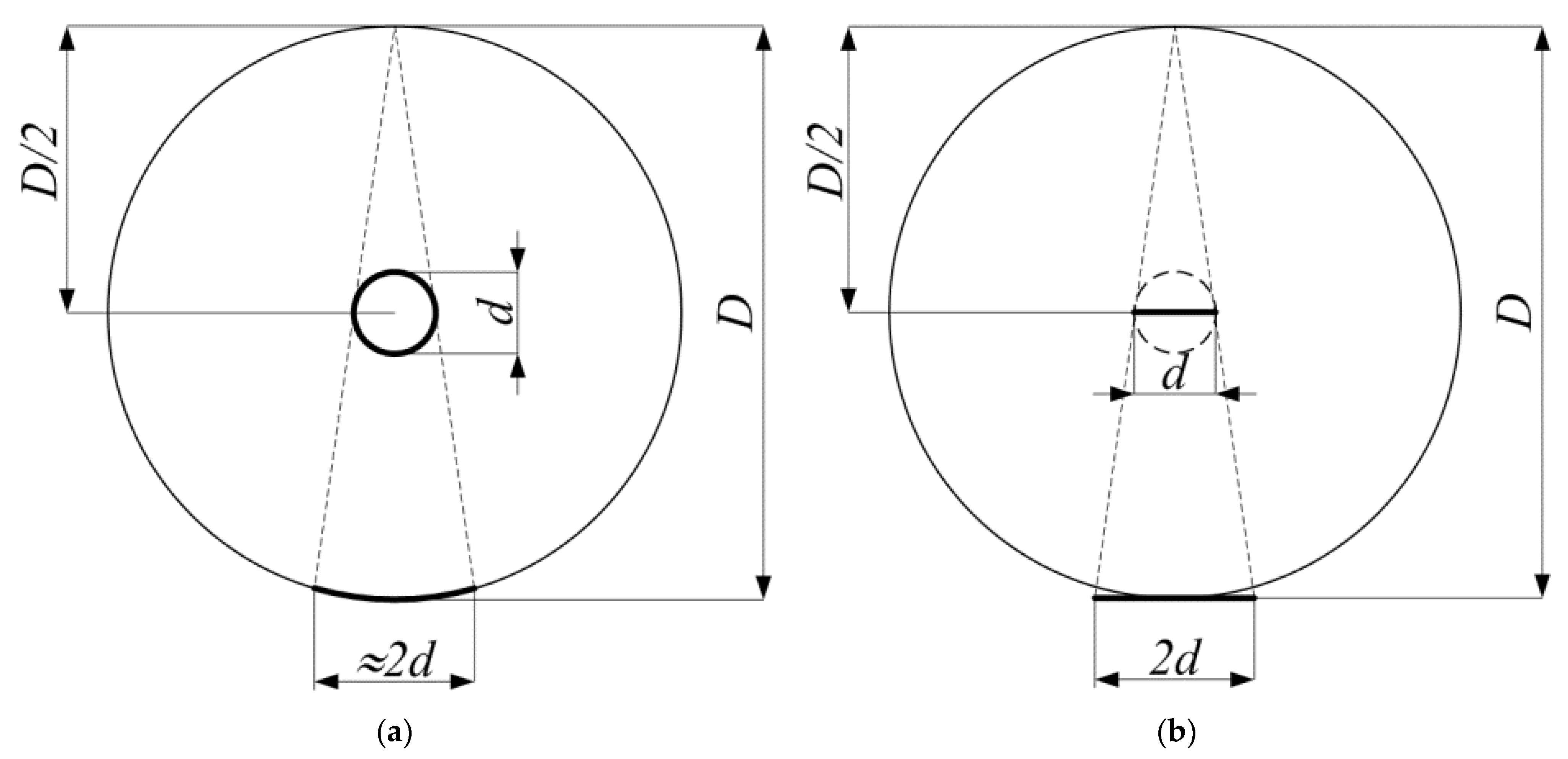
Next, we need to determine to what extent the irradiation created by the shaded part of the reflector after a single reflection is greater than the irradiation created after a single re-emission by the source in the center. Note that the irradiation created in a point of the reflector wall by a cylindrical surface of diameter
d with brightness
BLR(1 −
k), located in the centre of the circular cross section of diameter
D, is exactly equal to the irradiation created by a flat strip source of width
d with the same linear brightness located at a normal distance
D/2 to the viewing (
Figure 2a,b). Since
d <<
D, the shaded part of the cylindrical surface can also be considered as a stripe with the brightness
BLR and the width 2
d, located at a distance
D also perpendicular to the view direction (
Figure 2b). From these considerations, it is easy to find the desired difference. Due to the shading, the contribution to the irradiation of any reflector point after a single reflection will be
ILR(1 −
kd/
D) instead of
ILR in the absence of shading. Then, the difference is
ILR-
ILR(1 −
kd/
D) =
ILRkd/D. It is a part of a single reflected radiation that is irrevocably absorbed by the Lambertian source. Further, reasoning similarly, we find that the addition of the irradiation of the reflector surface as a result of a second reflection will be
ILR2(1 −
kd/
D)
2, the third reflection will be
ILR3(1 −
kd/
D)
3, and so on.
In exactly the same way as it is done when calculating the irradiation of the surface of the integrating spheres [
19], we represent the resulting irradiation of the surface of the cylindrical reflector
ISL as a result of multiple reflections in the form of a power series, which is summed up in the same way as in the theory of the integrating spheres:
IL =
P/(
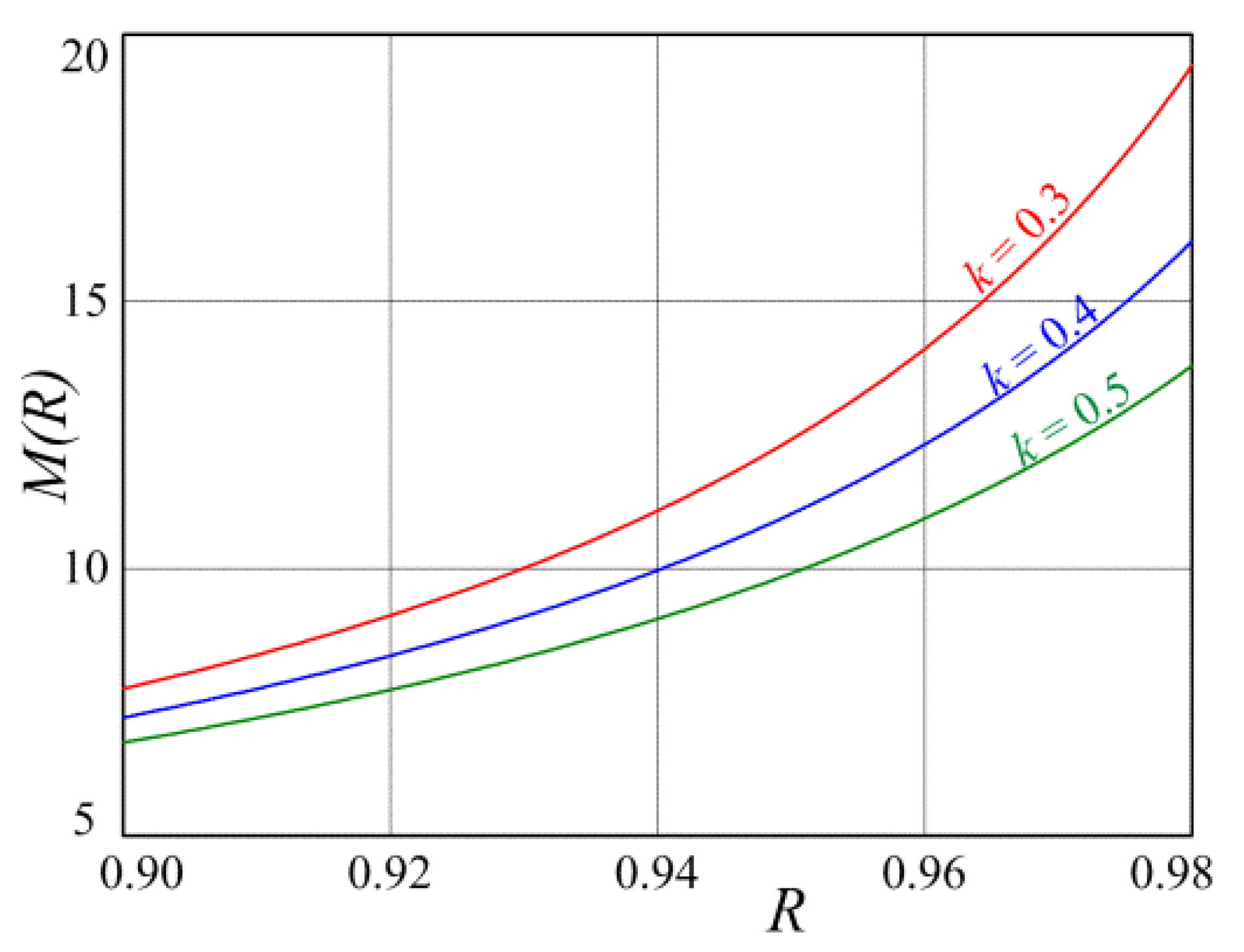
πDL) is the irradiation created by the central emitter at the distance of the surface of the cylindrical reflector without taking into account reflections from the surface of the reflector, that is, in the absence of a reflector. Then, we get the following formula for the coefficient of amplification of the radiation flux on the surface of the reflector due to multiple reflections and re-radiations:
where
M =
ISL/
IL is the radiation flux amplification factor on the cylinder surface.
5. Balance of Radiation Fluxes from Hg Amalgam Lamp in a Cavity with Diffuse Reflective Walls
The output of UV radiation depends on the diameter of the emitting medium (
d on
Figure 1) and the concentration of mercury atoms due to the effect of imprisonment (trapping) of the radiation of resonance lines [
20]. With an increase in the diameter of the medium
d, the electron temperature decreases, which leads to a decrease in the lamp efficiency. In this case, the output of UV radiation also decreases due to the “trapping” effect [
20,
21]. Inside a highly diffusely reflecting cavity (
R on
Figure 1), a significant portion of the radiation emitted by the surface of the emitting medium returns back. This is equivalent to an increase in the time of “trapping” of radiation. In this case, the action of the diffusely reflecting cavity will be equivalent to an increase in the diameter of the medium, that is, it will also cause a decrease in the electron temperature and the efficiency of radiation generation. In other words, physically returning a significant part of the radiation back to the lamp will lead to an increase in the concentration of atoms in the excited state of 6
3P1, an increase in stepwise ionization, and deactivation of excited states in inelastic collisions of the second kind with electrons [
20,
21,
22,
23].
Let us consider the balance of radiation fluxes inside a cylindrical diffuse reflector of length L and diameter D, on the axis of which a mercury amalgam lamp with a diameter of the emitting surface d is located (D ˂ L, d ˂ D). We assume that the surface of the cavity is an isotropic diffuse reflector with a diffuse reflectance R close to 1 and R < 1.
For
R values sufficiently close to 1, inside such a cavity, the proportion of irradiation of any area created by radiation diffusely reflected by the cavity surface is constant and equal to
RE, where
E is the irradiation of the cavity surface, created in total by the lamp and the diffusely reflecting surface. The emitting medium of the lamp is opaque to its own radiation. This means that the power of the absorbed radiation flux per unit length of the lamp is:
where
η is the transmission of the lamp wall (the fraction of incident radiation minus the radiation reflected by the wall of the quartz tube). It is known [
16] that the reflection coefficient of isotropic unpolarized radiation from a surface with a refractive index
n = 1.5 (fused quartz at a wavelength of 253.7 nm) is 9.2% (for normal directional radiation incident to the surface, the same value is 4%). To get inside, the radiation passes two surfaces (the outer and inner walls of the lamp). Taking into account the partial anisotropy of the radiation transmitted through the first surface, the total wall transmittance is
η ≈ 0.85.
A noticeable fraction of the absorbed radiation (50–60%) is re-emitted by excited mercury atoms back into the reflector cavity; the rest relaxes into heat in the processes of interatomic and electron–atom collisions or collisions of excited atoms with the tube wall. As we noted earlier in
Section 4, we denote the share absorbed due to these processes by
k. It should be noted here that the imbalance between the radiation incident on the lamp surface and the radiation emitted by the lamp, resulting from reflections from the lamp wall surfaces, both in the direction of the inside of the lamp and in the direction outward, when
R is close to 1, is small. This imbalance can be taken into account as a whole with a small correction of the value of the coefficient
k. With this in mind, we omit the factor
η in further formulas.
An expression for the total radiation flux onto the surface of the reflector, taking into account the diffusely reflected radiation, can be obtained if the procedure for calculating the radiation flux inside the photometric integrating spheres is followed, similar to that described, for example, in [
19,
24]. The same expression can be obtained if we proceed from the radiative balance in the cavity of a cylindrical diffuse reflector with a tubular lamp on its axis. The simple geometry of the problem simplifies the consideration, allowing simple methods to obtain a fairly accurate expression, which was derived in
Section 4.
Let us equate the radiation flux emitted by a section of the lamp of unit length
EL to the total absorption/transmission losses by the walls of the cavity and, in fact, by the emitting surface of the lamp:
S = π
D is the area of the cylindrical surface of the diffuse reflector of unit length and
s = π
d is the corresponding surface area of the emitting body of the lamp. From here, we get:
The first factor
EL/(π
D) can be interpreted as the fraction of the irradiation of the cavity surface created by the direct radiation of the lamp. With regard to the interpretation of experimental data, this approximation will be more valid if the radiation flux is measured in the middle of the lamp, placing the sensor at a distance that is small compared to its length and at a distance from the edges so that edge effects can be neglected. Then the second factor takes on the meaning of the irradiation amplification coefficient due to the contribution of radiation diffusely reflected by the walls:
In
Section 4, it was shown that a similar expression is obtained from the theory of integrating spheres, modified for the cylindrical case (Equation (4)).
7. Amalgam Lamp Performance in a Highly Diffuse Reflective Cavity
7.1. Dependence of Irradiation on Lamp Input Power
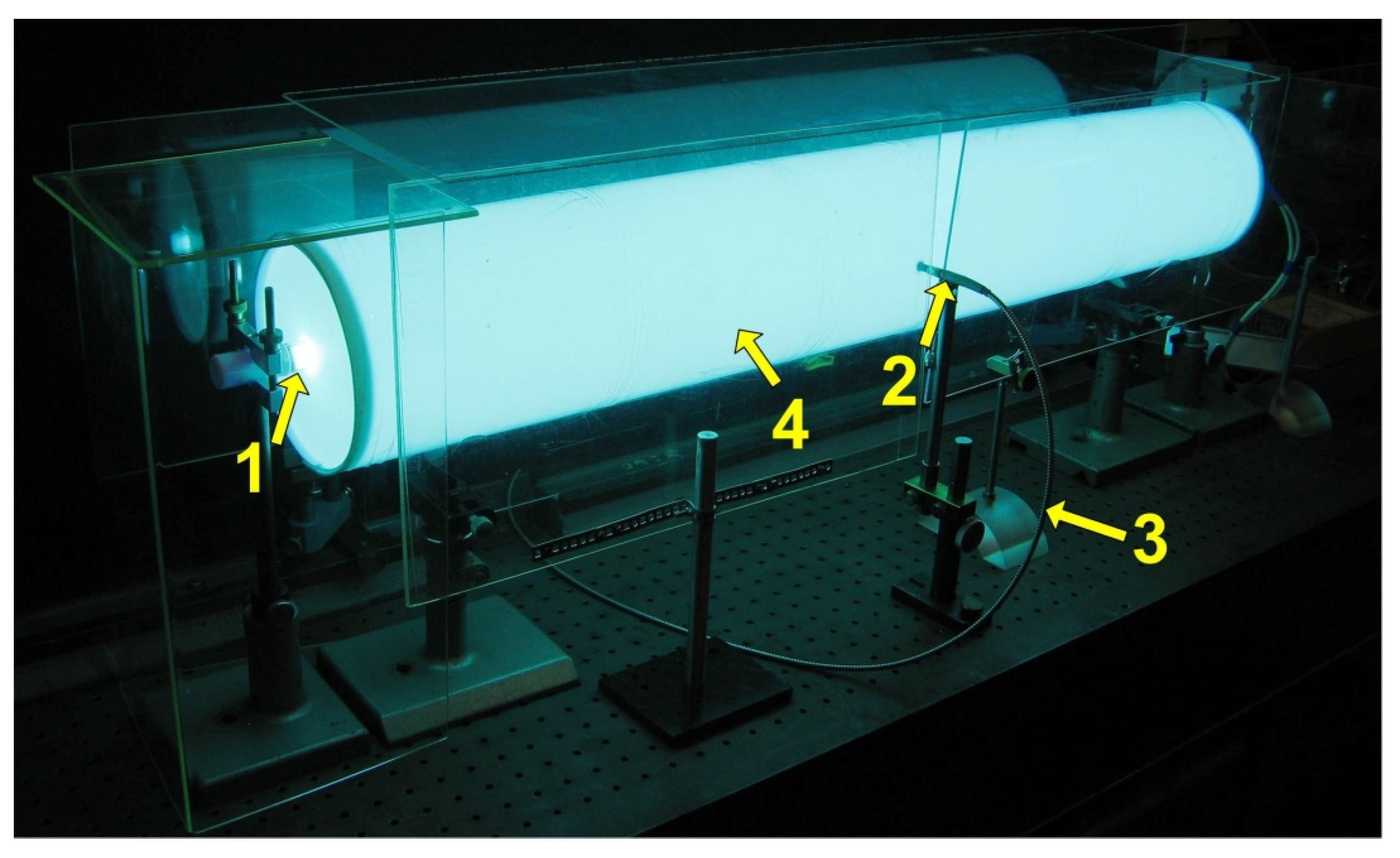
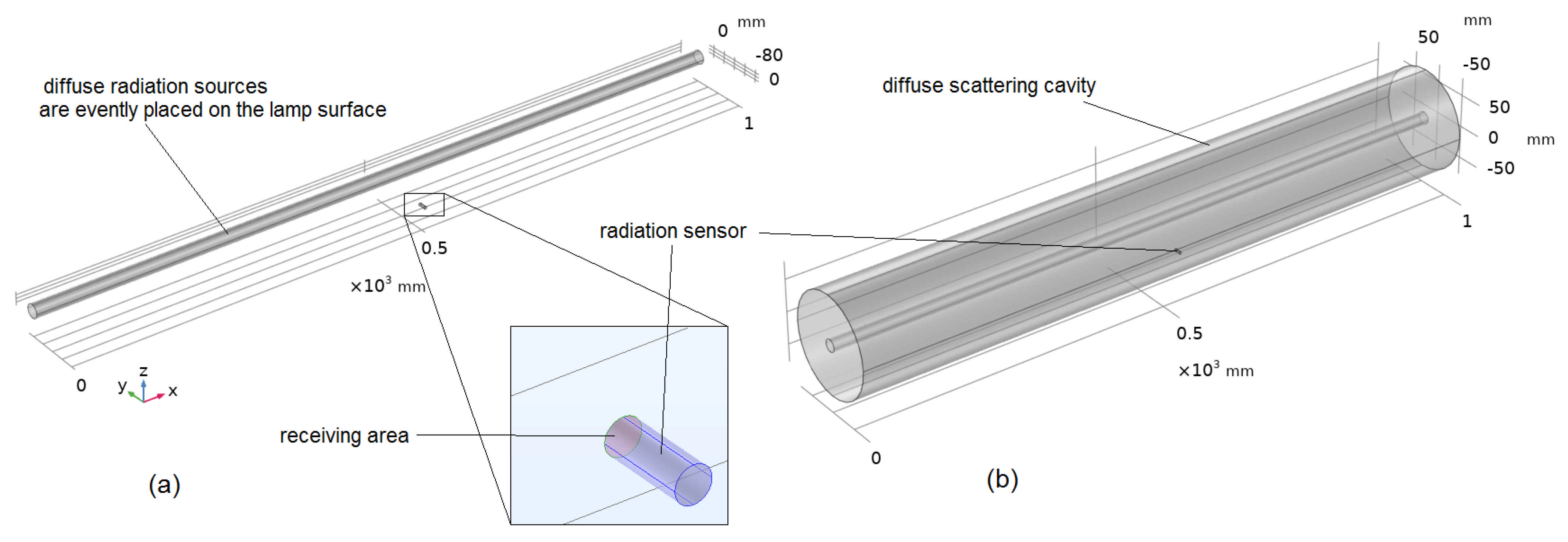
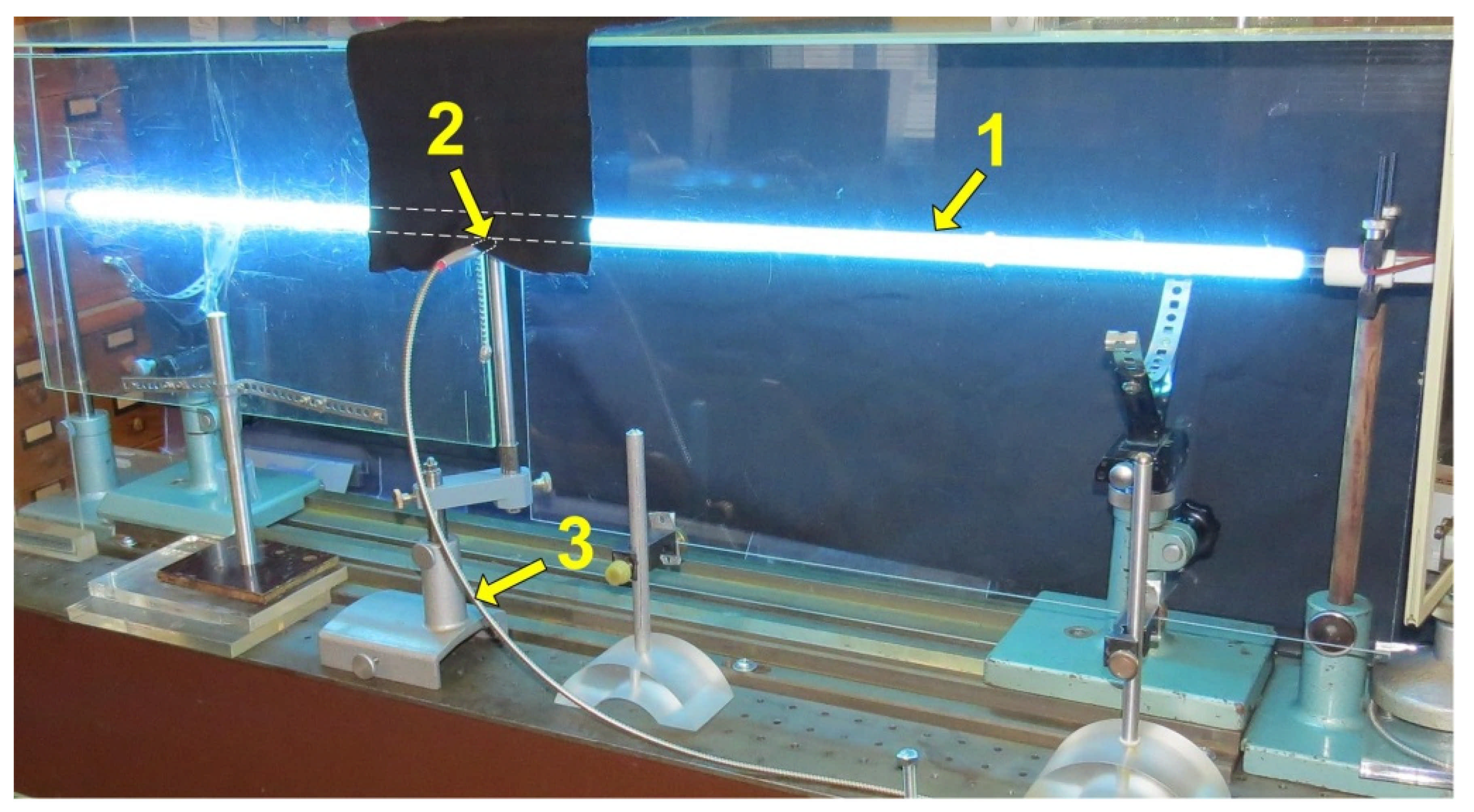
To determine the dependence of the irradiation generated by a mercury amalgam lamp at a wavelength of 253.7 nm on the electric power of the alternating current dissipated in the lamp, two series of experiments were carried out. In the first case, the irradiation in free space was recorded at a distance of 68 mm from the lamp wall. For the second series, the lamp was placed on the axis of a cylindrical ePTFE reflector (as in
Figure 4). The experimental parameters were similar to those described in
Section 6.1. A linear interpolation of the experimental dependence was carried out using the least squares method, and the coefficient of amplification of the light flux due to the diffusely reflecting cavity was found in comparison with the radiation flux at the same distance from the tube axis in free space. The results are shown in
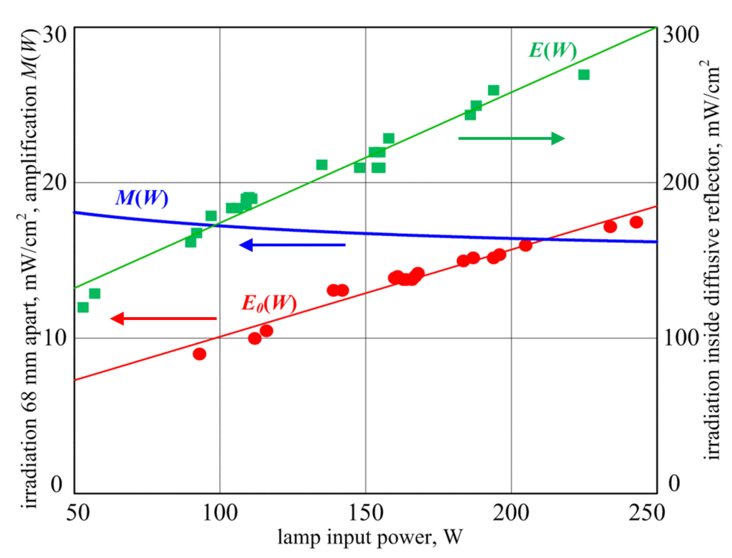
Figure 10.
The squares correspond to the radiation flux E(W) onto the wall of the cylindrical diffuse ePTFE reflector. The values of the symbols and the straight line drawn through them refer to the right axis. Circles are the radiation flux E0(W) at a distance of 68 mm from the lamp wall in the absence of a reflector (corresponds to the reflector surface); the values of these points and the interpolation line refer to the left axis. The blue curve with a negative slope is the amplification factor of the radiation flux in the cavity M(W) = E(W)/E0(W) (M(W) = 18.1 ÷ 16.2), which numerically refers to the left axis. Along the axes, the ordinate axes are the radiation flux in the line λ = 253.7 mW/cm2 at a distance of D/2 = 77.5 mm from the lamp axis without a reflector (left axis) and with a reflector (right axis); the abscissa axis is the electrical power W dissipated in the lamp.
In the experiments, the achieved flux amplification factor decreased from M = 18.1 to M = 16.2 with an increase in the discharge power of the amalgam lamp from W = 50 W to W = 250 W.
7.2. Heating and Cooling the Amalgam
An amalgam lamp is designed to operate at a specific amalgam temperature. At this temperature, the optimum vapor pressure of mercury and the maximum radiation flux in the 253.7 nm line are achieved. In experiments with different electric powers of the lamp inside the reflector, the temperature of the amalgam had to be controlled; the amalgam was cooled at an excess electric power and heated up at an insufficient one. Radiation returned by the reflector back to the lamp served as an additional channel for heating the amalgam inside the cylinder with a highly diffuse reflection coefficient. Therefore, to optimize the long-term operation of the lamp, it was necessary to shield the amalgam from radiation. The air temperature in the reflector cavity was controlled by pumping the air flow through the side walls of the cavity with a small fan.
Nevertheless, during the experiments, the authors found it possible not to make technical efforts to ensure long-term optimal operation of the lamp. In most cases, the problem of determining the radiation flux in the optimal mode could be solved in the process of warming up the lamp within 2 min after switching it on at the moment when the radiation flux reached its maximum value, after which it began to decrease due to violation of optimal conditions upon further heating.
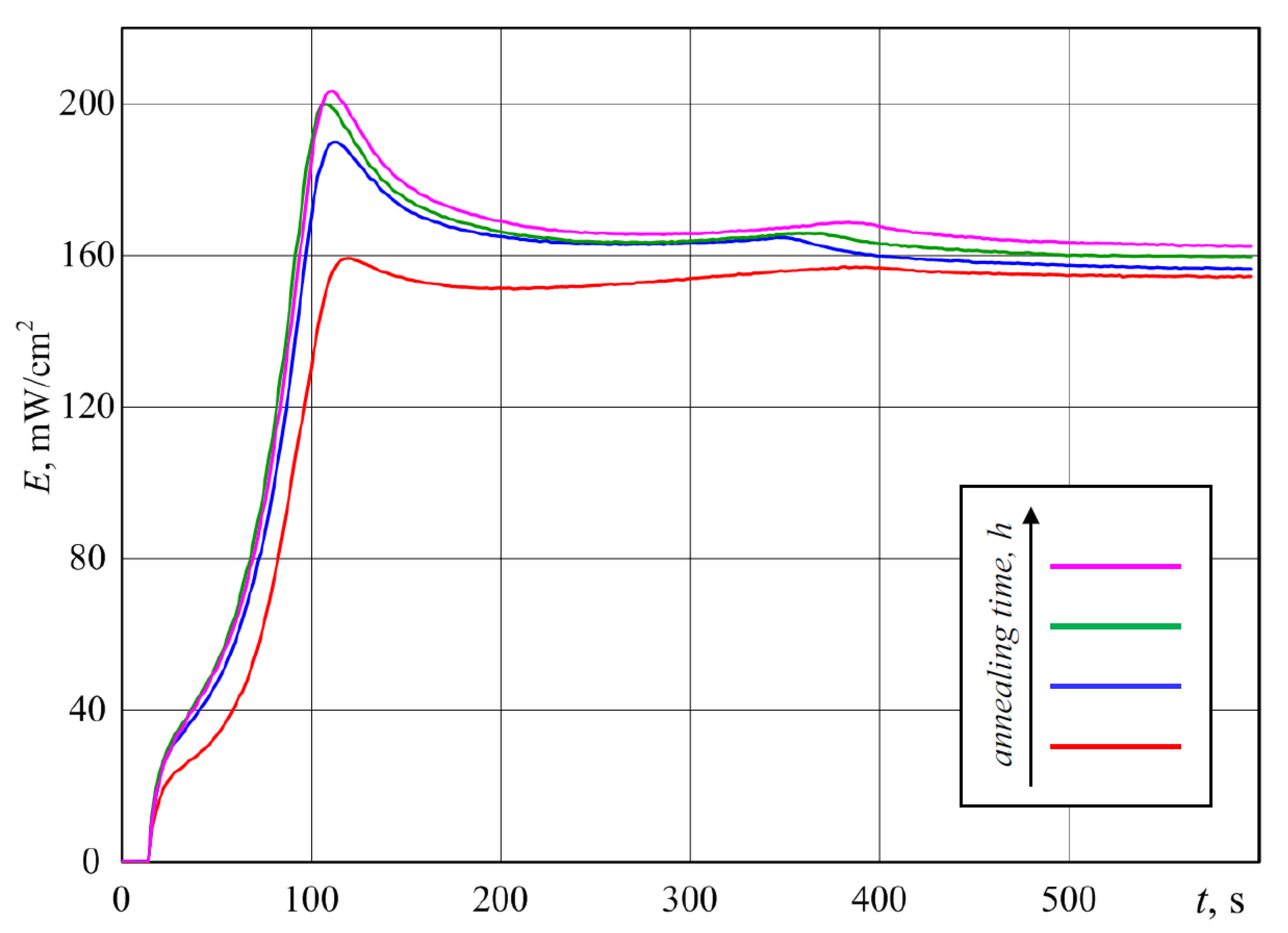
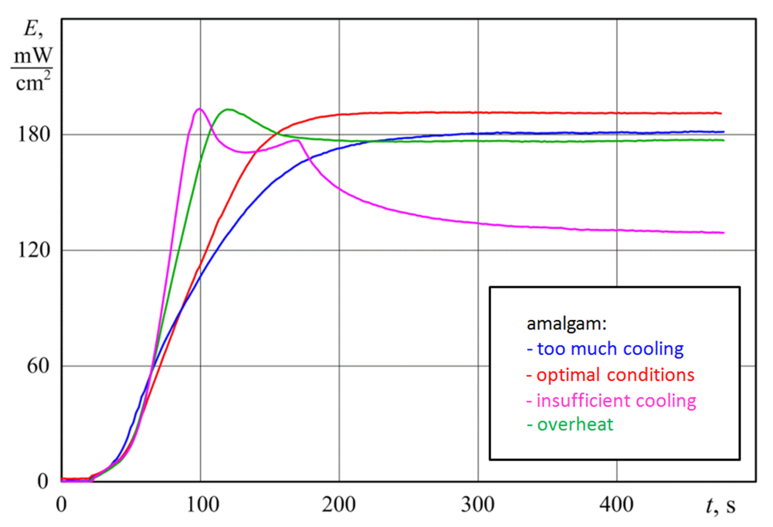
Figure 11 shows the diagrams of the increase in the radiation flux under various conditions of cooling the amalgam.
The red curve is closest to the optimal working conditions of the amalgam. The blue curve corresponds to too much cooling of the amalgam. The pink and green curves correspond to different levels of insufficient cooling and overheating of the amalgam during long-term operation. However, it can be seen that the maximum radiation flux achieved during the heating process was the same with a high accuracy in all cases, except for the case of excessive cooling. In this case, the faster the maximum value of the radiation flux was reached, the worse the cooling conditions.
Therefore, in most measurements, it was the maximum value of the radiation flux that was determined when the lamp was heated under conditions of insufficient cooling of the amalgam. When operating without a reflector at low values of the electric power, the lamp was preheated at a power higher than the nominal until the amalgam overheated; then, the electric power rapidly decreased. The radiation flux also dropped sharply. Then, in the process of cooling the amalgam to the optimal value, the radiation flux increased, after which it decreased, since the pumping power was insufficient for long-term operation of the amalgam at the optimal temperature. The maximum value of the radiation flux was recorded as being achieved at the optimal temperature regime of the amalgam.
7.3. UV-Annealing Effect of ePTFE
As mentioned earlier in
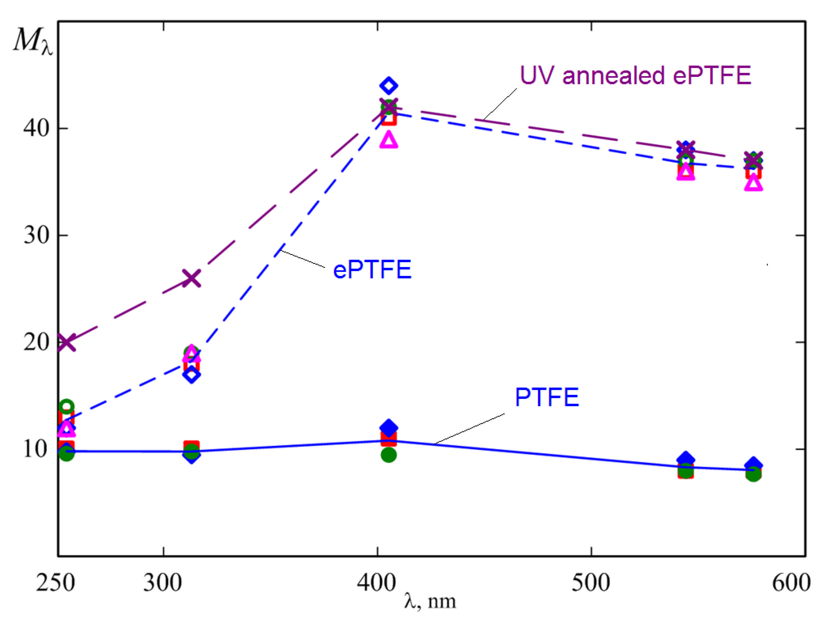
Section 6.2, an increase in the gain was observed during the experiments after ePTFE annealing for several hours with UV radiation at a wavelength of 253.7 nm (crosses and dashed line in
Figure 7). This increase in radiation flux was registered in several successive lamp switchings on diagrams. The difference between diagrams is explained by the annealing of the material by UV irradiation for 0.5 h between successive diagrams (
Figure 12). Under the influence of UV irradiation, the desorption of impurities from the pores of ePTFE occurred, which reduced UV radiation absorption in the material and eventually increased the coefficient of diffuse reflection of UV radiation.
9. Application in UV Air Purifier
In the presence of a diffusely reflecting cavity, the radiation flux to the receiving area increased up to 20 times in the experiment (
Figure 7,
Figure 8,
Figure 9 and
Figure 10), although the data cannot be suitable for describing an air purifier, since there is no pumping of the medium through the cavity. At the same time, the obtained results clearly demonstrated the prospects of using such diffusely reflecting materials as PTFE and ePTFE for internal placement in the purifier cavity. Let us consider some of the features of this possible application.
9.1. Presence of Geometrical Losses
As can be seen from Equation (8), to achieve high values of amplification
M, it is necessary to use a cavity with a small value of radiation loss
σ. For the considered case with a cylindrical geometry, these losses are limited only by the absorption of radiation in the lamp and are equal to
σ =
kd/
D. However, in the case of the purifier, the presence of additional losses is inevitable simply because it is necessary to pump air through the cavity. The cavity has open ends for the inlet and outlet of the air flow through which radiation is lost. The fraction of the inner surface through which radiation leaves the cavity is called geometric losses. They increase
σ by the ratio of the areas of the open ends
Sin and
Sout to the area of the diffuser
SR and decrease
M:
The increase in σ due to geometric losses does not allow the use of materials with a high coefficient of diffuse reflection of radiation as efficiently as possible. It becomes fundamentally important to reduce the value of geometric losses in UV air purifiers and cleaners, which have a highly effective coefficient of diffuse reflection of germicidal radiation.
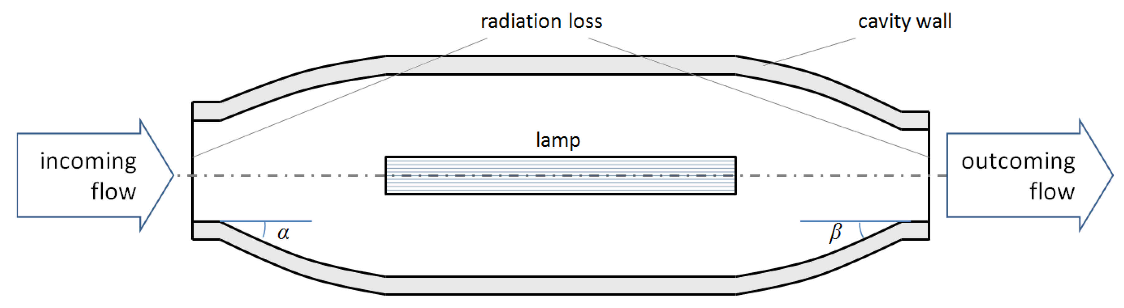
9.2. Diffuser–Confuser Type of Input and Output Air Ports
There are several options for reducing geometric loss of UV radiation through input and output air ports. One of them is the use of diffuser–confuser geometry of a UV reflecting cavity (
Figure 19). In real conditions, all the elements of the construction inside the cavity (for example, lamp clamps) may also be of diffusely reflecting materials.
This geometry allows the implementation of the so-called “optical shutter”, which “locks” UV radiation in the cavity of the emitter, and the reduction of geometric losses with a corresponding decrease in the inlet and outlet sections of the air flow in the cavity of the purifying channel filled with radiation of germicidal range [
13]. However, in this case, in the indicated sections, the speed of the air flow increased proportionally and the power consumption for pumping air increased sharply due to the loss of pressure. That is, with a significant decrease in geometric losses and, consequently, a decrease in the power of UV radiation, the power consumption for pumping air increases many times, which significantly reduces (or even completely eliminates) the positive effect of increasing irradiation inside the cavity of the purifier. Additionally, in order to reduce pressure losses and flow resistance, in the geometry, it is necessary to observe small values of the angles of the diffuser and confuser (up to ~12–14° for
α and
β [
35],
Figure 19. This increases the size of the purifier, the complexity, and cost of its manufacture.
Thus, the main obstacle to the widespread use of air purifiers with a large amplification of UV radiation is the implementation of a fairly compact “optical shutter” at the inlet and outlet of the air channel. On the one hand, it should provide low radiation losses in the cavity. On the other hand, it should be sufficiently compact and create the lowest possible gas-dynamic losses for the air flow pumped through the channel.
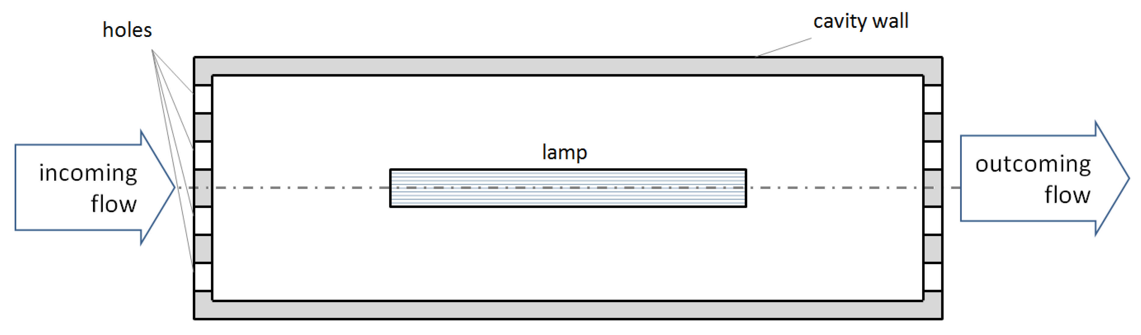
9.3. Air Ports in the Form of Multiple Perforated Holes
Another solution of the problem is to use multiple holes perforated in the end walls of the cylindrical cavity to provide air circulation together with UV radiation trapping (
Figure 20). If the walls are made of the same diffusely reflecting material as the cavity, then the dimensions of the channel do not actually change [
10,
13]. The reduction in geometric losses here will depend on the ratio of the area of the holes
Sh to the area of the cavity
SR:
Due to the decrease of the air flow cross section in the perforated holes, there is also an increase in the power consumption for pumping the air flow. In addition, it must be remembered that the total energy consumption of the UV air purifier increases with an increase in its air flow capacity (with an increase in the air flow through the cavity).
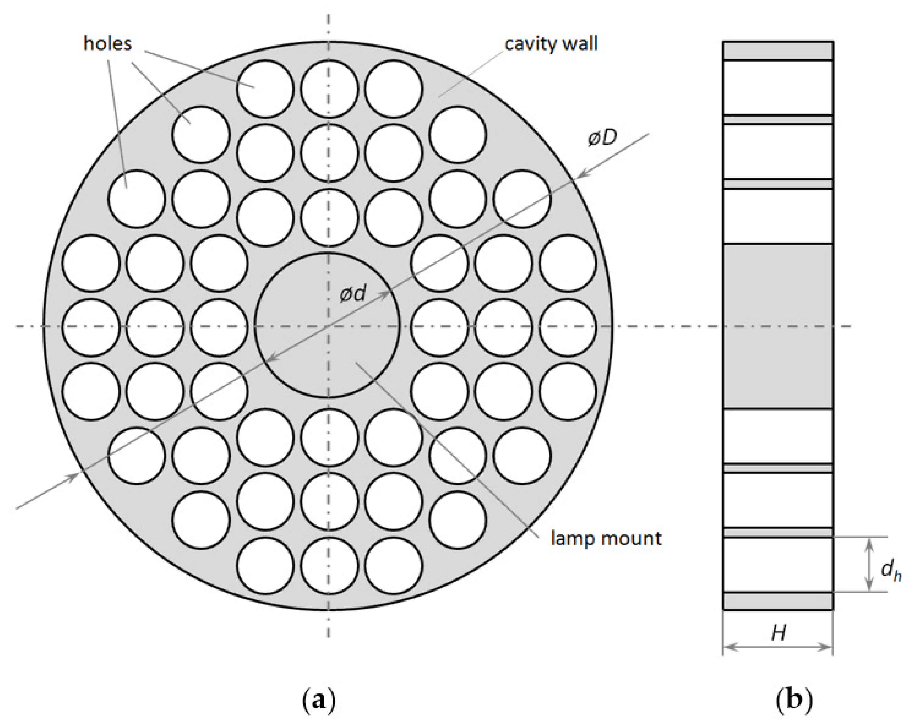
9.4. Radiation Propagation in Perforation Channels
When the thickness of the perforated walls
H is increased to a value several times higher than the minimum cross-sectional dimension of the holes in the wall
dh, the resistance to the gas flow does not increase much, since the pressure loss mainly occurs at the inlet and outlet of the holes, but not in the hole channel itself (
Figure 21).
Taking into account the high coefficient of diffuse reflection of the wall material, when considering the propagation of radiation in such a channel, one can draw an analogy with the collisionless Knudsen flow of low-pressure gas [
13]:
When considering deep holes (H > dh), most of the photons in the germicidal range do not pass through the holes but are effectively reflected back. The probability of such a passage is determined by the geometry of the hole (circle, cone, rectangle, etc.), as well as the ratio of its minimum transverse dimension to the depth.
To estimate the probability of radiation passing through a channel (slit, groove, hole), one can use Clausing functions. They are determined by the theory of transmission probabilities (or Clausing factors) through cylindrical tubes, which was developed by Clausing [
36,
37,
38] and reformulated for conical tubes by Iczkowski [
39]. The Clausing function,
w(
x), is the probability of a particle located at position
x to escape through the end of the duct. The value
η(
x) = 1 −
w(
x) is related with the distribution of collisions of particles with the walls of the system.
Consider values of Clausing functions calculated for cylindrical holes in [
40]. Then, at the inner boundary of the diffusely reflecting cavity (i.e., at
x = 0)
η(0) will be equal to the probability of radiation reflection
Rk from the end walls of the cavity with diffuse reflection coefficient
R = 1. For other values, the formula for
Rk takes the form:
As mentioned above, to achieve high
Rk values, the depth of the holes must be greater than their diameter (
rh—radius,
dh = 2
rh,
H/
dh > 1).
Table 3 shows the
Rk values for these holes.
Table 3 shows that the higher the
H/
dh ratio, the more radiation is returned to the cavity due to diffuse scattering “back” in the perforation channels. In practice, such a decrease in geometric loss is equivalent to a decrease in the
Sh/
SR ratio or a decrease in the fraction of the hole area where radiation is lost.
Consider a cylindrical cavity of the air channel with a diffusely reflecting inner surface with a coefficient
R and input and output ends with multiple perforated holes. The perforated walls at the ends form optical shutters of thickness
H, in which circular holes with a diameter
dh are made. Let us estimate the value of radiation loss
σ for the geometry. The absorption of radiation in the lamp (
kd/
D) must be taken into account. The total geometric radiation loss will contain the ratio of the area of the holes to the area of the entire cavity (
Sh/
SR) as well as the term describing the radiation incident on the holes in the perforated walls (−
Sh/(
Sin +
Sout)
Rk(
H/
dh)). Here, the minus means the return of radiation from the perforated channels back to the cavity of the purifier. The
Sh value is the sum of the perforation fractions of the inlet and outlet walls of the air channel (
Sh =
Sh_in +
Sh_out). Then, the formula for amplification
M will take the form:
9.5. Reduction of Gas-Dynamic Loss
For an air flow, the pressure loss is determined by the value of
Sh/(
Sin +
Sout) and, as a first approximation, weakly depends on
H for not too small dimensions of an individual perforation element (i.e., when the pressure drop in the channel (hole) itself can be neglected). For real air flow velocities (up to several meters per second, [
9,
10,
11,
12,
13,
14]) in a UV air purifier it is sufficient that the minimum perforation size
dh exceeds 1 mm. It can be said that such a technical solution makes it possible to effectively separate the geometric losses for radiation and gas-dynamic losses for the air flow and thereby significantly increase the integral productivity and efficiency of the UV air purifier.
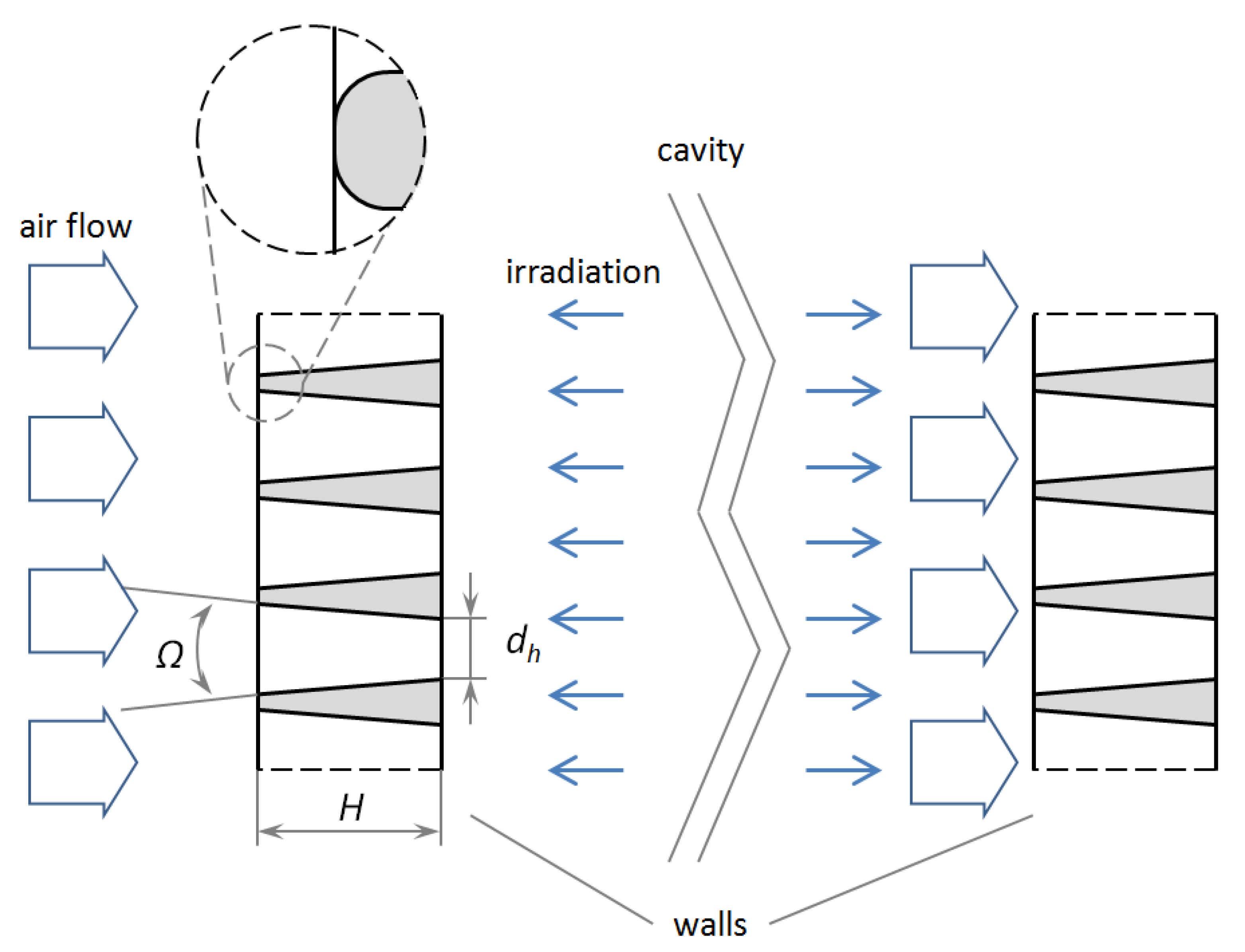
In order to further reduce gas-dynamic losses, perforation can be made with a transverse dimension that decreases in the direction of the air flow [
13]. For example, the perforation holes can be frusto-conical with a preferably small apex angle
Ω. This design can further reduce the power consumption for pumping air through the air channel (
Figure 22).
With a large value of the air flow rate through the air channel of the purifier, the cross-sectional area of the perforation should be at least 40–45% of the cross-sectional area of the air flow in the channel. A significant proportion of the perforated area ensures sufficiently low pressure losses and a low level of power consumption for pumping. At the same time, geometric losses of UV radiation remain at a fairly low level. To further reduce the pressure loss across the optical shutter, edge rounding on the air inlet and outlet sides can be used (
Figure 21).
10. Conclusions
To increase the energy efficiency of UV air purifiers, it is necessary to increase the efficiency of using germicidal radiation. This is especially important if it is necessary to provide a high degree of sterilization or to sterilize air containing microorganisms more resistant to UV radiation. This increase can be achieved by using materials with highly diffuse reflection of UV radiation. The design of a cylindrical cavity made of a highly diffuse reflective material with a cylindrical radiation source located longitudinally on its axis is best suited for both experiments and theoretical description. With slight modifications discussed in the paper, the same design can be used as the basis of an UV air purifier.
PTFE and ePTFE are considered to be effective materials for diffuse reflection of the UV radiation due to their high reflectivity and low absorption in the UV region. An ozone-free mercury amalgam UV lamp with the main radiation at a wavelength of 253.7 nm was considered as a radiation source. It was shown in a two-dimensional examination under idealized conditions that the irradiation at any point inside a cylindrical volume bounded by diffusely reflecting walls tends to that near the radiation source of a smaller radius located longitudinally on the axis of a cylinder. If the cavity contains some microparticles (dust or aerosol with bacteria or viruses), the conditions of their irradiation are the same throughout the cavity provided the diffuse reflectance coefficient of the walls is high.
Experiments were carried out to demonstrate the amplification of the UV irradiation in cylindrical cavities of PTFE and ePTFE depending on a diffuse reflection coefficient of the wall material. In the experiments, amplification up to 20 times in the UV spectral range was observed. The dependences of irradiation at 253.7 nm on input electric power of the lamp were obtained. The experimentally implemented processes of heating and cooling the amalgam of Hg lamp, which directly affect the amplification in the radiation flux in the cylindrical diffuse reflector, are described.
For the idealized case of cylindrical radiation source and a reflector arranged coaxially, a theory of radiation flux amplification similar to the theory of photometric integrating spheres was developed. Within the framework of the theory, mathematical expression was obtained for the radiation amplification coefficient depending on the characteristics of the diffusely reflecting material and Lambert radiation source partially absorbing and partially diffusely re-emitting the exposing radiation flux. The formula adequately describes the experimental results.
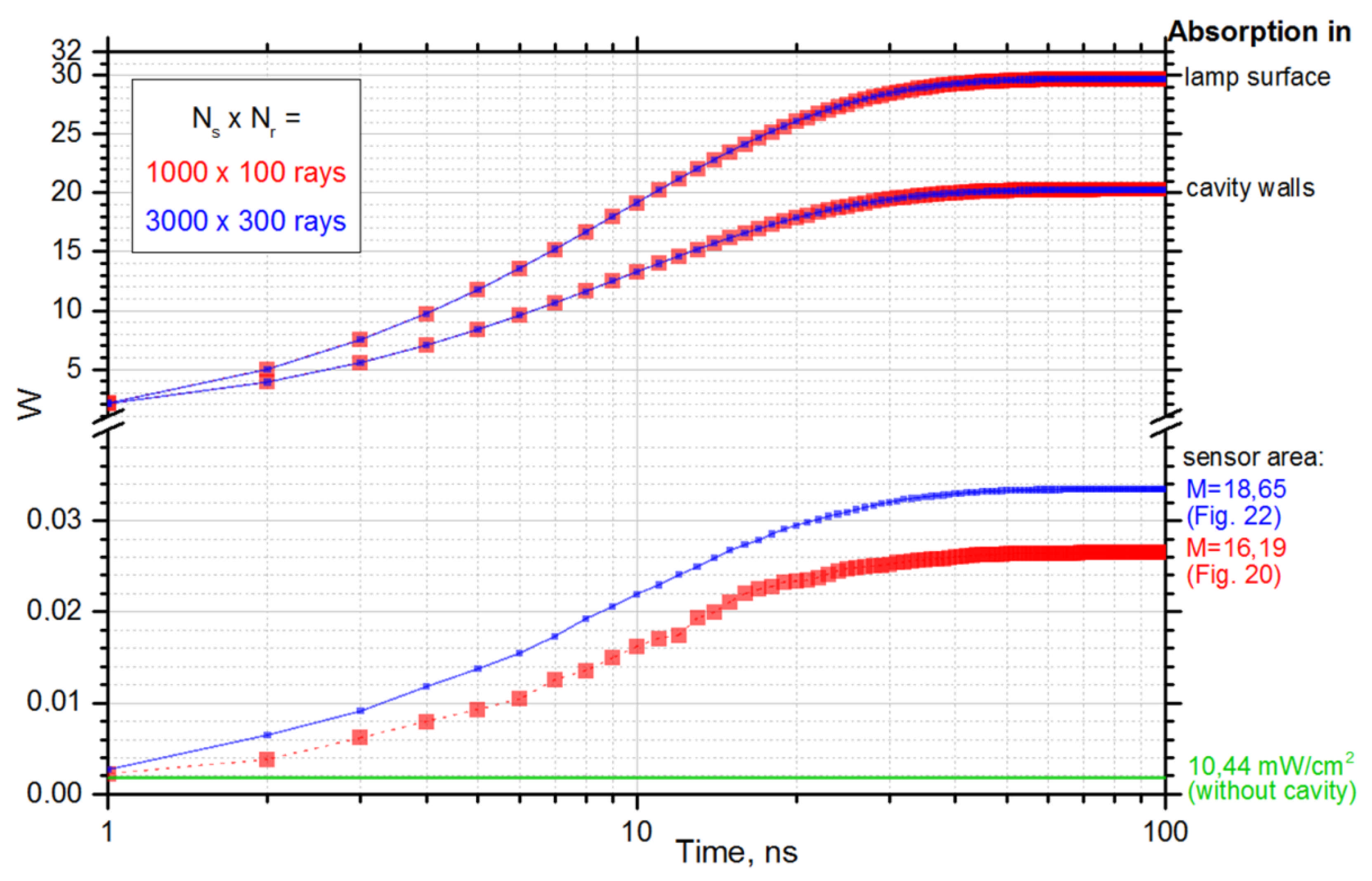
Numerical calculations performed for the experimental geometry by the ray tracing method gave similar results. The features of probability density functions on the surfaces of the emitter and the walls of the diffuse cavity were considered. The performed simulation gave a good description of the amplification of irradiation from a UV mercury lamp when it is used in a cylindrical diffusely reflective cavity. Taking into account the absorption of radiation, conclusions were drawn about the applicability of the calculation method in further research and developments in UV germicidal areas.
The resulting significant amplification of the UV irradiation makes it promising to use highly diffuse reflection materials in the cavities of UV air purifiers. Formulas describing UV irradiation multiplication coefficient in different designs of the UV air purifying channels were obtained. When considering the propagation of radiation through the holes perforated in diffuse reflective material of the input and output air purifier ports, the radiation transport through the holes was considered to be analogous to the collisionless Knudsen molecular flow. This made it possible to estimate the fraction of radiation returned to the cavity using Clausing coefficients and to refine the multiplication of the irradiation flux.
The results of this work will be in demand among engineers producing equipment for germicidal applications. It makes sense to focus further research on numerical calculations of various designs of UV air purifiers with highly diffuse reflecting cavity walls. Similar data are presented in papers [
18,
41,
42], in which the flow of a medium with particles through a cavity was simulated. These particles simulated harmful microorganisms that died when they absorbed a certain dose of UV radiation; after that, the particles disappeared from the computational domain. This is also advisable because, as noted in
Section 2, in order to increase the efficiency of the UV air purifier, it is necessary to take into account the costs of the power consumed by it for pumping the medium to be cleaned.


