
Research on a Control Strategy of the Symmetrical Four-Roller Bending Process Based on Experiment and Numerical Simulation


Abstract
:1. Introduction
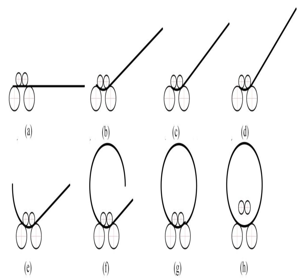
2. SFRB Process
3. Control Strategy
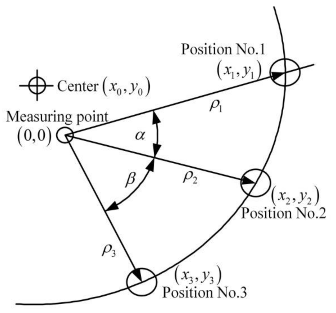
3.1. Online Monitoring of Curvature
3.2. Online Identification of Springback Law
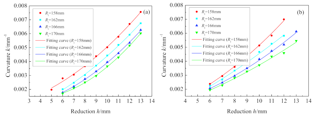
3.2.1. Experimental Identification
3.2.2. Numerical Simulation Identification
3.2.3. The Least Square Method
3.3. Online Prediction of Final Reduction
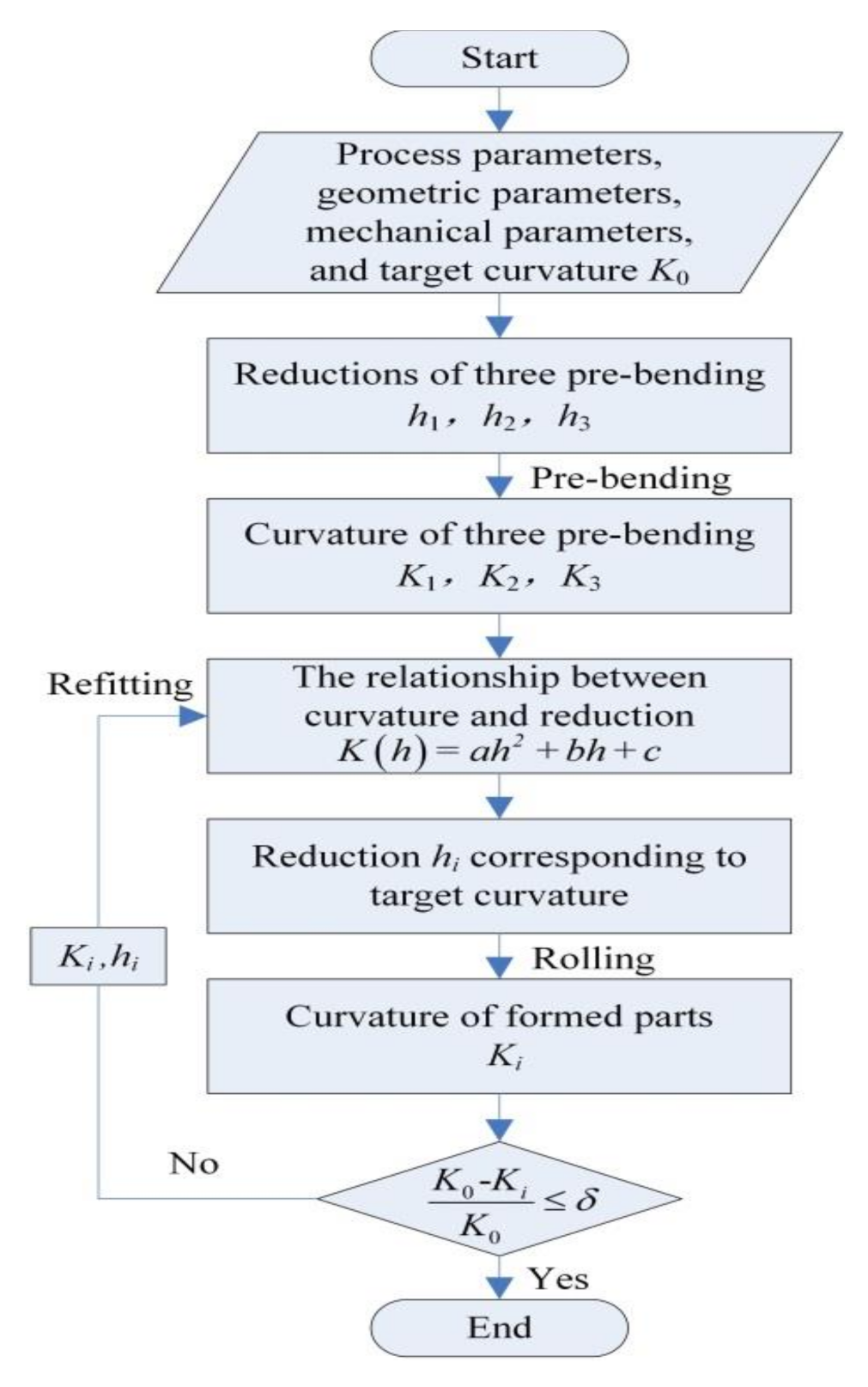
3.4. Control Strategy Process
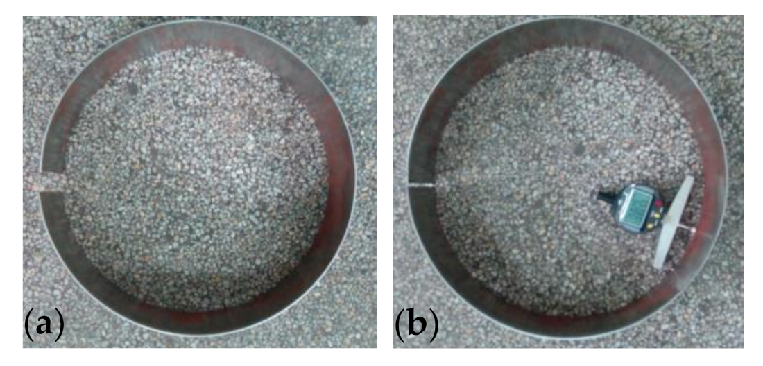
4. Experimental Verification
5. Conclusions
- For this process, a control strategy is proposed, including on-line monitoring of curvature, on-line identification of the springback law, on-line prediction of final reduction, and control strategy process.
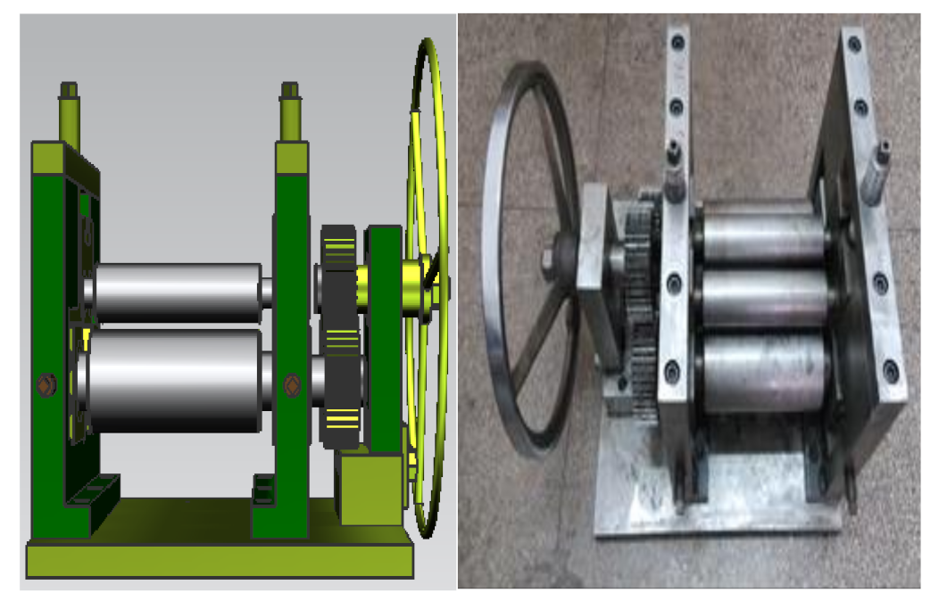
- A convenient and reliable on-line curvature monitoring method is proposed. The SFRB device was developed and the finite element model was established. Through physical experiments and numerical simulation, the quantitative relationship between the reduction and the curvature was established, which is a quadratic function relationship, as follows:
- 3.
- Through physical experiments, the control strategy of SFRB process was verified. The relative error of curvature radius of the final formed parts can be controlled within 0.8%. This research provides new method for intelligent rolling of steel plate.
Author Contributions
Funding
Institutional Review Board Statement
Informed Consent Statement
Data Availability Statement
Conflicts of Interest
References
- Zhao, J.; Cao, H.Q.; Ma, L.X.; Wang, F.Q.; Li, S.B. Study on intelligent control technology for the deep drawing of an axi-symmetric shell part. J. Mater. Process Technol. 2004, 151, 98–104. [Google Scholar] [CrossRef]
- Gandhi, A.H.; Gajjar, H.V.; Raval, H.K. Mathematical modelling and finite element simulation of pre-bending stage of three-roller plate bending process. Proc. ASME Int. Manuf. Sci. Eng. Conf. 2008, 1, 617–625. [Google Scholar] [CrossRef]
- Zhang, Z.Q.; Song, J.L.; Fu, J.H.; Li, Y.T.; Guo, Y.N. A refined model of three-roller elastoplastic asymmetrical pre-bending of plate. J. Iron Steel Res. Int. 2014, 21, 328–334. [Google Scholar] [CrossRef]
- Hu, W.; Wang, Z.R. Theoretical analysis and experimental study to support the development of a more valuable roll-bending process. Int. J. Mach. Tool. Manu. 2001, 41, 731–747. [Google Scholar] [CrossRef]
- Gandhi, A.H.; Raval, H.K. Analytical and empirical modeling of top roller position for three-roller cylindrical bending of plates and its experimental verification. J. Mater. Process Technol. 2008, 197, 268–278. [Google Scholar] [CrossRef]
- Fu, Z.; Tian, X.; Chen, W.; Hu, B.; Yao, X. Analytical modeling and numerical simulation for three-roll bending forming of sheet metal. Int. J. Adv. Manuf. Technol. 2013, 69, 1639–1647. [Google Scholar] [CrossRef]
- Quan, T.H.; Champliaud, H.; Feng, Z.K.; Salem, J.; My, D.T. Heat-assisted roll-bending process dynamic simulation. Int. J. Model. Simul. 2013, 33, 54–62. [Google Scholar] [CrossRef]
- Chudasama, M.K.; Raval, H.K. Bending force prediction for dynamic roll-bending during 3-roller conical bending process. J. Manuf. Process. 2014, 16, 284–295. [Google Scholar] [CrossRef]
- Yu, G.C.; Zhao, J.; Zhao, F.P. Elastic-plastic secondary indeterminate problem for thin-walled pipe through the inner-wall loading by three-point bending. Mech. Based. Des. Struc. 2017, 45, 219–238. [Google Scholar] [CrossRef]
- Yu, G.C.; Zhao, J.; Zhai, R.X.; Ma, R.; Wang, C.G. Theoretical analysis and experimental investigations on the symmetrical three-roller setting round process. Int. J. Adv. Manuf. Technol. 2018, 94, 45–56. [Google Scholar] [CrossRef]
- Zeng, J.; Liu, Z.; Champliaud, H. FEM dynamic simulation and analysis of the roll-bending process for forming a conical tube. J. Mater. Process Technol. 2008, 198, 330–343. [Google Scholar] [CrossRef]
- Ktari, A.; Antar, Z.; Haddar, N. Modeling and computation of the three-roller bending process of steel sheets. J. Mech. Sci. Technol. 2012, 26, 123–128. [Google Scholar] [CrossRef]
- Feng, Z.K.; Champliaud, H.; Dao, T.M. Numerical study of non-kinematical conical bending with cylindrical rolls. Simul. Model. Pract. Theory 2009, 17, 1710–1722. [Google Scholar] [CrossRef]
- Salem, J.; Champliaud, H.; Feng, Z.K.; Dao, T.M. Experimental analysis of an asymmetrical three-roll bending process. Int. J. Adv. Manuf. Technol. 2016, 83, 1823–1833. [Google Scholar] [CrossRef]
- Huang, X.Y.; Yu, G.C.; Zhao, J.; Mu, Z.K.; Zhang, Z.Y.; Ma, R. Numerical simulation and experimental investigations on a three-roller setting round process for thin-walled pipes. Int. J. Adv. Manuf. Technol. 2020, 107, 355–369. [Google Scholar] [CrossRef]
- Hua, M.; Baines, K.; Cole, I.M. Bending mechanisms, experimental techniques and preliminary tests for the continuous four-roll plate bending process. J. Mater. Process Technol. 1995, 48, 159–172. [Google Scholar] [CrossRef]
- Hua, M.; Lin, Y.H. Large deflection analysis of elastoplastic plate in steady continuous four-roll bending process. Int. J. Mech. Sci. 1999, 41, 1461–1483. [Google Scholar] [CrossRef]
- Gao, G.Y.; Yu, G.C.; Zhao, J.; Zhang, Z.Y. Rolling round process of four-roll and its springback analysis. J. Plast. Eng. 2017, 24, 55–62. [Google Scholar]
- Wu, K.; Sun, Y.; Cao, C.; Zhou, C.; Liu, Q.; Chang, X. On simulation analysis of plate forming and deformation compensation technology of the side roll for four-roll plate bending machine. Procedia Eng. 2017, 207, 1617–1622. [Google Scholar] [CrossRef]
- Zhou, C.; Sun, Y.; Wu, K.; Liu, Q.Y.; Chang, X.; Sheng, Y.L. Modeling and analysis of process parameters in multi-pass four-roll bending. J. Plast. Eng. 2018, 25, 35–41. [Google Scholar]
- Gu, X.; Franzke, M.; Bambach, M.; Hirt, G. Experimental and numerical investigation of grid sheet bending behavior in four-roll bending. CIRP Ann. Manuf. Technol. 2010, 59, 303–306. [Google Scholar] [CrossRef]
- Yu, G.C.; Zhao, J.; Xu, C.F. Development of a symmetrical four-roller bending process. Int. J. Adv. Manuf. Technol. 2019, 104, 4049–4061. [Google Scholar] [CrossRef]
- Li, J.; Li, X.F.; Chen, G.Y.; Zuo, D.W.; Sun, Y.B.; Li, M.; Zhu, C.F. Experiment and simulation of two-axle bending of 301 stainless steel strip with different hardness values. J. Plast. Eng. 2017, 24, 28–32. [Google Scholar]
- Gong, J.P.; Li, X.F.; Zuo, D.W.; Kang, X.J.; Qiu, J.B. Three-dimensional FEA of manufacturing process of small-diameter split sleeve by two-axle bending. China Mech. Eng. 2015, 26, 1117–1124. [Google Scholar]
- Zhao, J.; Yu, G.C.; Ma, R. A mechanical model of symmetrical three-roller setting round process: The static bending stage. J. Mater. Process Technol. 2016, 231, 501–512. [Google Scholar] [CrossRef]
- Yu, G.C.; Zhai, R.X.; Zhao, J.; Ma, R. Theoretical analysis and numerical simulation on the process mechanism of two-roller straightening. Int. J. Adv. Manuf. Technol. 2018, 9, 4011–4021. [Google Scholar] [CrossRef]
- Li, J. Research on Intelligent Control Technology for Forming the Large Diameter Longitudinal-Seam Submerged ARC Welded Pipes with JCO Process; Yanshan University: Qinhuangdao, China, 2009. [Google Scholar]
- Zhao, J.; Song, X.K. Control strategy of multi-point bending one-off straightening process for LSAW pipes. Int. J. Adv. Manuf. Technol. 2014, 72, 1615–1624. [Google Scholar] [CrossRef]
- Zhao, J.; Zhan, P.P.; Ma, R.; Zhai, R.X. Control strategy of over-bending setting round for pipe-end of large pipes by mould press type method. Trans. Nonferr. Metal. Soc. 2012, 22, 329–334. [Google Scholar] [CrossRef]
- Zhao, J.; Zhan, P.P.; Ma, R.; Zhai, R.X. Prediction and control of springback in setting round process for pipe-end of large pipe. Int. J. Pres. Ves. Pip. 2014, 116, 56–64. [Google Scholar] [CrossRef]


| Upper Roller Diameter Du/mm | Lower Roller Diameter D1/mm | Upper Roller Spacing Lu/mm | Lower Roller Spacing L1/mm | Roller Length Lr/mm |
|---|---|---|---|---|
| 60 | 120 | 70 | 150~180 | 220 |
| Materials | Lower Roller Diameter R1/mm | a (10−6) | b (10−6) | C (10−6) | R2 |
|---|---|---|---|---|---|
| 304 | 158 | 74.78 | −669.38 | 2100 | 0.9951 |
| 162 | 41.58 | −194.2 | 305.59 | 0.9966 | |
| 166 | 46.63 | −373.36 | 1110 | 0.9922 | |
| 170 | 40.77 | −287.53 | 619.36 | 0.9946 | |
| ST12 | 158 | 43.82 | 59.00 | −606.53 | 0.9920 |
| 162 | 41.46 | 24.55 | −465.38 | 0.9933 | |
| 166 | 35.22 | −9.52 | −241.73 | 0.9992 | |
| 170 | 21.22 | 122.38 | −553.51 | 0.9987 |
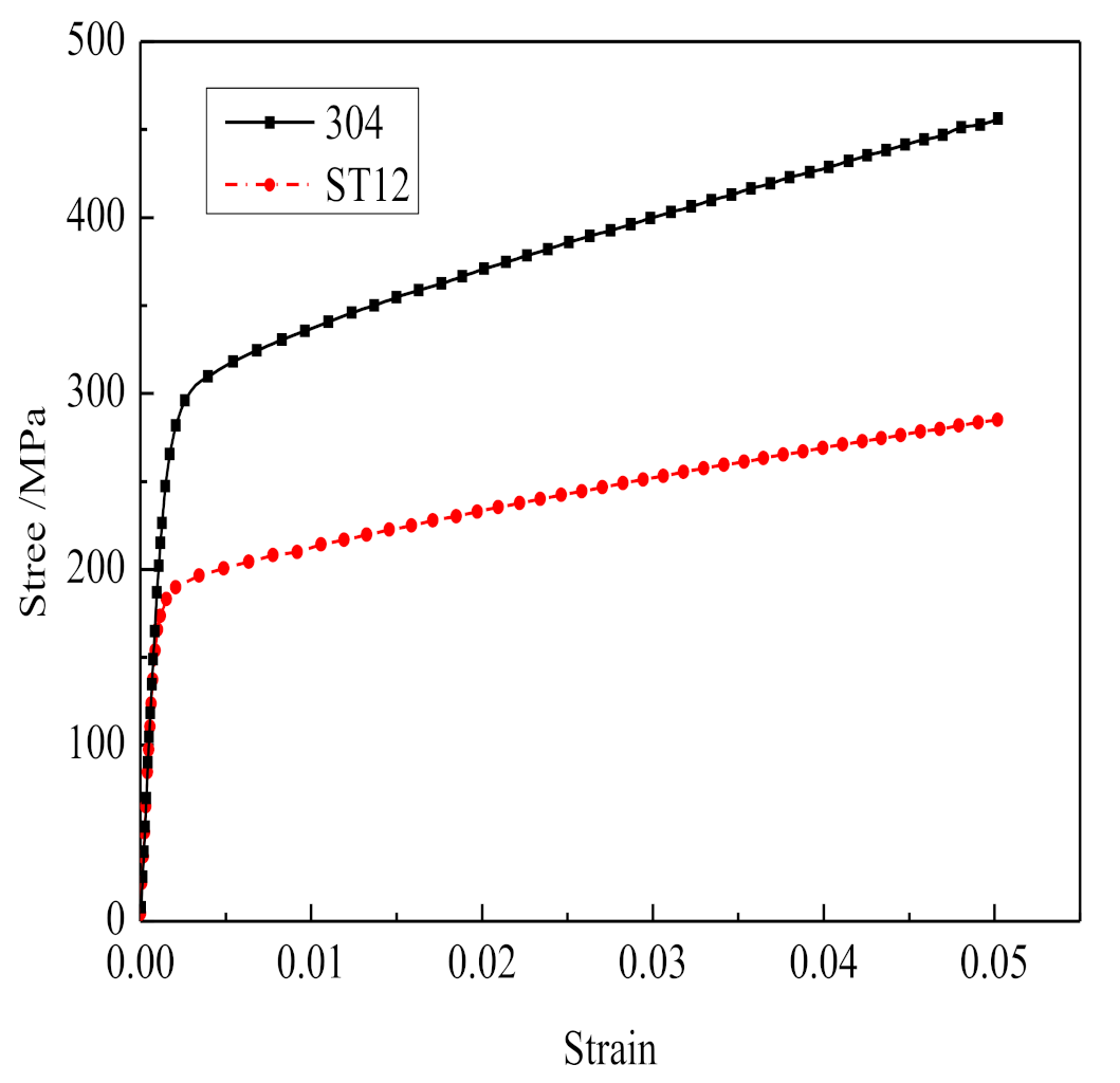
| Materials | Yield Stress/MPa | Young’s Modulus/MPa | Plastic Tangent Modulus/MPa |
|---|---|---|---|
| 304 | 257 | 182,000 | 2560 |
| ST12 | 194 | 202,000 | 1610 |
| Materials | Lower roller Diameter R1/mm | a (10−6) | b (10−6) | c (10−6) | R2 |
|---|---|---|---|---|---|
| 304 | 158 | 30.72 | 202.26 | 52.28 | 0.9961 |
| 162 | 13.13 | 376.64 | −531.6 | 0.9965 | |
| 166 | 22.31 | 147.19 | 367.64 | 0.9970 | |
| 170 | 13.65 | 230.74 | 56.21 | 0.9936 | |
| ST12 | 158 | 29.98 | 141.69 | 642.76 | 0.9974 |
| 162 | 26.03 | 191.59 | −117.48 | 0.9995 | |
| 166 | 33.16 | 5.19 | 556.62 | 0.9996 | |
| 170 | 46.85 | −275.72 | 1690 | 0.9996 |
| Procedures | Reduction h/mm | Curvature Radius p /mm | Target Curvature Radius p t/mm | Error /% |
|---|---|---|---|---|
| First pre-bending | 5.3 | 1219.5 | — | — |
| Second pre-bending | 8.1 | 436.7 | — | |
| Third pre bending | 11.2 | 220.8 | — | |
| Rolling | 13.2 | 158.7 | 150 | 5.8 |
| Modified rolling | 13.4 | 150.4 | 0.3 |
| Procedures | Reduction h/mm | Curvature Radius p /mm | Target Curvature Radius p t/mm | Error/% |
|---|---|---|---|---|
| First pre-bending | 5.8 | 1762.3 | — | — |
| Second pre-bending | 8.5 | 663.8 | — | |
| Third pre bending | 11.2 | 327.2 | — | |
| Rolling | 14.6 | 161.2 | 150 | 7.5 |
| Modified rolling | 14.9 | 151.1 | 0.7 |
Publisher’s Note: MDPI stays neutral with regard to jurisdictional claims in published maps and institutional affiliations. |
© 2021 by the authors. Licensee MDPI, Basel, Switzerland. This article is an open access article distributed under the terms and conditions of the Creative Commons Attribution (CC BY) license (https://creativecommons.org/licenses/by/4.0/).
Share and Cite
Cao, H.; Yu, G.; Yang, C.; Zhao, J. Research on a Control Strategy of the Symmetrical Four-Roller Bending Process Based on Experiment and Numerical Simulation. Symmetry 2021, 13, 940. https://doi.org/10.3390/sym13060940
Cao H, Yu G, Yang C, Zhao J. Research on a Control Strategy of the Symmetrical Four-Roller Bending Process Based on Experiment and Numerical Simulation. Symmetry. 2021; 13(6):940. https://doi.org/10.3390/sym13060940
Chicago/Turabian StyleCao, Hongqiang, Gaochao Yu, Chunfang Yang, and Jun Zhao. 2021. "Research on a Control Strategy of the Symmetrical Four-Roller Bending Process Based on Experiment and Numerical Simulation" Symmetry 13, no. 6: 940. https://doi.org/10.3390/sym13060940
APA StyleCao, H., Yu, G., Yang, C., & Zhao, J. (2021). Research on a Control Strategy of the Symmetrical Four-Roller Bending Process Based on Experiment and Numerical Simulation. Symmetry, 13(6), 940. https://doi.org/10.3390/sym13060940