
Inter-Frame Based Interpolation for Top–Bottom Packed Frame of 3D Video


Abstract
1. Introduction
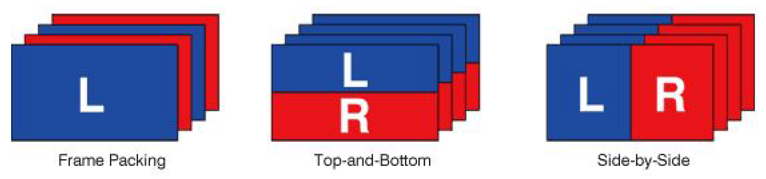
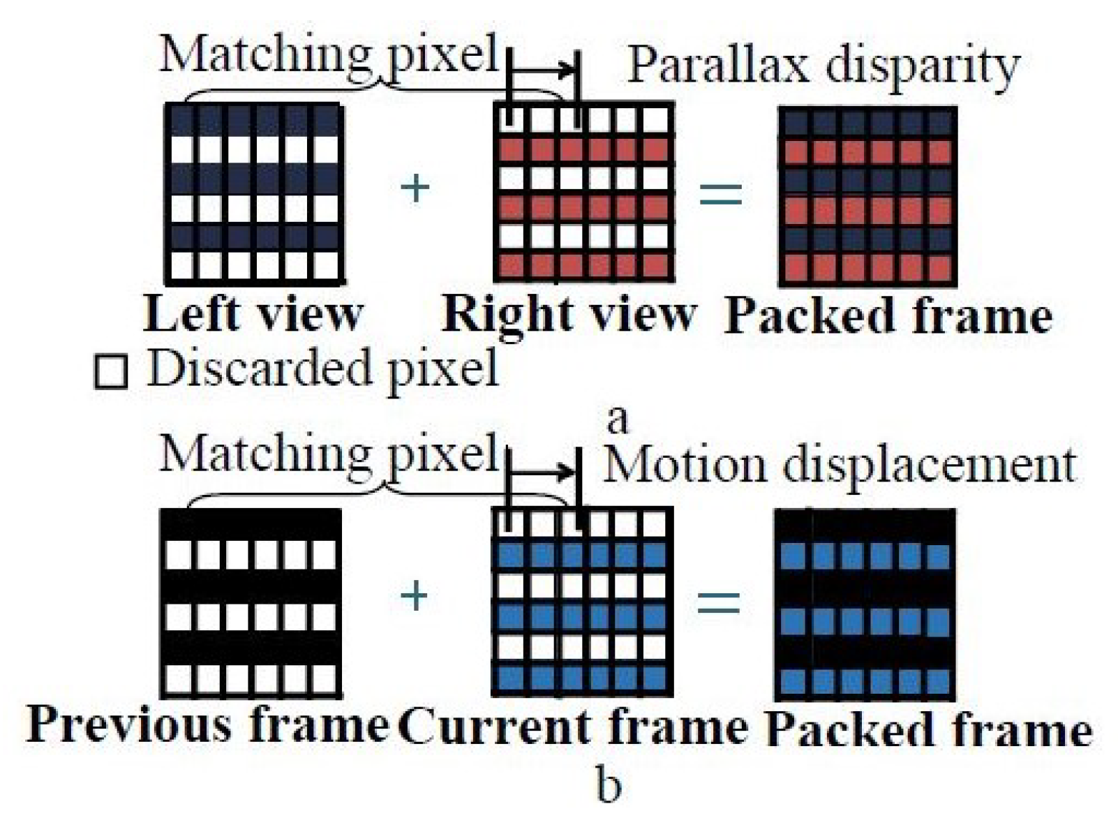
2. Frame-Compatible Top–Bottom Packing
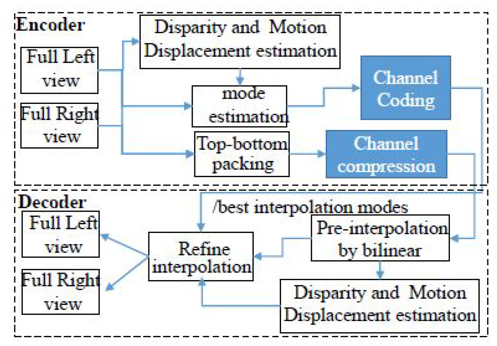
3. Proposed Inter-Frame Based Interpolation
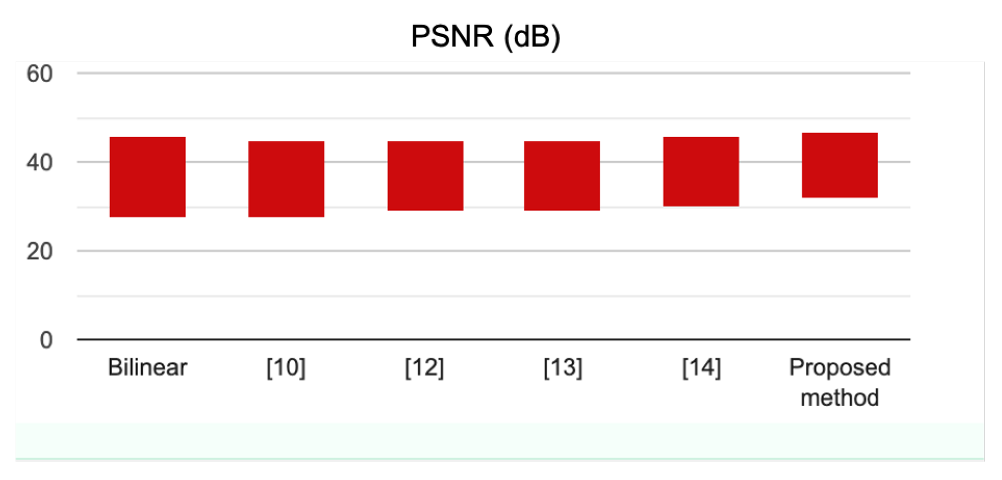
4. Experimental Results
5. Discussion and Conclusions
Author Contributions
Funding
Institutional Review Board Statement
Informed Consent Statement
Data Availability Statement
Conflicts of Interest
References
- Vetro, A.; Lou, W.H.; Flynn, M. TV Architecture Supporting Multiple 3D Services. In Proceedings of the 2010 Digest of Technical Papers International Conference on Consumer Electronics (ICCE), Las Vegas, NV, USA, 9–13 January 2010; IEEE: New York, NY, USA, 2010; pp. 135–136. [Google Scholar]
- Le, A.V.; Jung, S.W.; Won, C.S. Directional joint bilateral filter for depth images. Sensors 2014, 14, 11362–11378. [Google Scholar] [CrossRef] [PubMed]
- Nguyen, H.; Le, A.V.; Won, C.S. Fast selective interpolation for 3D depth images. In Proceedings of the IEEE International Symposium on Broadband Multimedia Systems and Broadcasting, Seoul, Korea, 27–29 June 2012; pp. 1–5. [Google Scholar]
- Vetro, A.; Wiegand, T.; Sullivan, G.J. Overview of the stereo and multiview video coding extensions of the H.264/MPEG-4 AVC standard. Proc. IEEE 2011, 99, 626–642. [Google Scholar] [CrossRef]
- Hur, N.; Lee, H.; Lee, G.S.; Lee, S.J.; Gotchev, A.; Park, S.I. 3DTV broadcasting and distribution systems. IEEE Trans. Broadcast. 2011, 57, 395–407. [Google Scholar] [CrossRef]
- Le, A.V.; Won, C.S. Key-point based stereo matching and its application to interpolations. Multidimens. Syst. Signal Process. 2017, 28, 265–280. [Google Scholar] [CrossRef]
- Siu, W.C.; Hung, K.W. Review of Image Interpolation and Super-Resolution. In Proceedings of the 2012 Asia Pacific Signal and Information Processing Association Annual Summit and Conference, Hollywood, CA, USA, 3–6 December 2012; pp. 1–10. [Google Scholar]
- Giachetti, A.; Asuni, N. Real-time artifact-free image upscaling. IEEE Trans. Image Process. 2011, 20, 2760–2768. [Google Scholar] [CrossRef] [PubMed]
- Vo, D.T.; Sole, J.; Yin, P.; Gomila, C.; Nguyen, T.Q. Selective data pruning-based compression using high-order edge-directed interpolation. IEEE Trans. Image Process. 2009, 19, 399–409. [Google Scholar] [CrossRef] [PubMed]
- Li, X.; Orchard, M.T. New edge-directed interpolation. IEEE Trans. Image Process. 2001, 10, 1521–1527. [Google Scholar] [PubMed]
- Le, A.V.; Kim, H.M.; Won, C.S. Fast interpolation for line-pruned images. J. Electron. Imaging 2011, 20, 033010. [Google Scholar]
- Tourapis, A.; Pahalawatta, P.V.; Leontaris, A.; Stec, K.J. Encoding and Decoding Architectures for Format Compatible 3D Video Delivery. U.S. Patent 9,774,882, 26 September 2017. [Google Scholar]
- Morita, C. Content Reproducing Apparatus and Method. U.S. Patent 12/502,318, 22 June 2010. [Google Scholar]
- Won, C.S. Mode selective interpolation for stereoscopic 3D video in frame-compatible top-bottom packing. Multidimens. Syst. Signal Process. 2013, 24, 221–233. [Google Scholar] [CrossRef]
- Di Stefano, L.; Marchionni, M.; Mattoccia, S. A fast area-based stereo matching algorithm. Image Vis. Comput. 2004, 22, 983–1005. [Google Scholar] [CrossRef]
- Song, W.; Le, A.V.; Yun, S.; Jung, S.W.; Won, C.S. Depth completion for kinect v2 sensor. Multimed. Tools Appl. 2017, 76, 4357–4380. [Google Scholar] [CrossRef]
- FHG-HHI. Stereo-Video Database. 2020. Available online: http://sp.cs.tut.fi/mobile3dtv/stereo-video/ (accessed on 22 October 2020).
- Chen, M.J.; Su, C.C.; Kwon, D.K.; Cormack, L.K.; Bovik, A.C. Full-reference quality assessment of stereopairs accounting for rivalry. Signal Process. Image Commun. 2013, 28, 1143–1155. [Google Scholar] [CrossRef]
- Wang, Z.; Bovik, A.C.; Sheikh, H.R.; Simoncelli, E.P. Image quality assessment: From error visibility to structural similarity. IEEE Trans. Image Process. 2004, 13, 600–612. [Google Scholar] [CrossRef] [PubMed]
- Wang, Z.; Li, Q. Information content weighting for perceptual image quality assessment. IEEE Trans. Image Process. 2010, 20, 1185–1198. [Google Scholar] [CrossRef] [PubMed]
- Ponomarenko, N.; Silvestri, F.; Egiazarian, K.; Carli, M.; Astola, J.; Lukin, V. On Between-Coefficient Contrast Masking of DCT Basis Functions. In Proceedings of the Third International Workshop on Video Processing and Quality Metrics, Scottsdale, AZ, USA, 25–26 January 2007; Volume 4. [Google Scholar]
- Zhang, L.; Zhang, L.; Mou, X.; Zhang, D. FSIM: A feature similarity index for image quality assessment. IEEE Trans. Image Process. 2011, 20, 2378–2386. [Google Scholar] [CrossRef] [PubMed]
- Wang, Z.; Bovik, A.C. Modern Image Quality Assessment; Synthesis Lectures on Image, Video, and Multimedia Processing; Morgan & Claypool: San Rafael, CA, USA, 2006; Volume 2, 156p. [Google Scholar]
- BT.500. Methodologies for the Subjective Assessment of the Quality of Television Images. 2020. Available online: https://www.itu.int/rec/R-REC-BT.500 (accessed on 22 October 2020).


| Mode | Interpolation Condition | Mode | Interpolation Mode |
|---|---|---|---|
| 1 | 2 | ||
| 3 | 4 | ||
| 5 | 6 | ||
| 7 | 8 | ||
| 9 | 10 | ||
| 11 | 12 | ||
| 13 | 14 |
| Method | Bilinear | [9] | [12] | [13] | [14] | Proposed |
|---|---|---|---|---|---|---|
| - | (dB) | dB | Method dB | dB | dB | dB |
| Book | 34.66 | 34.39 | 35.66 | 35.82 | 36.66 | 37.90 |
| Car | 38.93 | 38.91 | 39.12 | 38.87 | 39.68 | 41.38 |
| Door | 36.16 | 36.06 | 37.24 | 37.12 | 38.26 | 39.76 |
| Horse | 32.69 | 32.24 | 32.72 | 32.91 | 33.73 | 35.34 |
| Moabit | 31.93 | 31.94 | 33.12 | 33.01 | 34.22 | 36.24 |
| Bullinger | 43.33 | 43.49 | 43.51 | 43.42 | 44.37 | 45.68 |
| Mean | 36.28 | 36.19 | 36.90 | 36.86 | 37.82 | 39.38 |
| Standard Deviation | 4.27 | 4.41 | 4.05 | 3.96 | 3.93 | 3.80 |
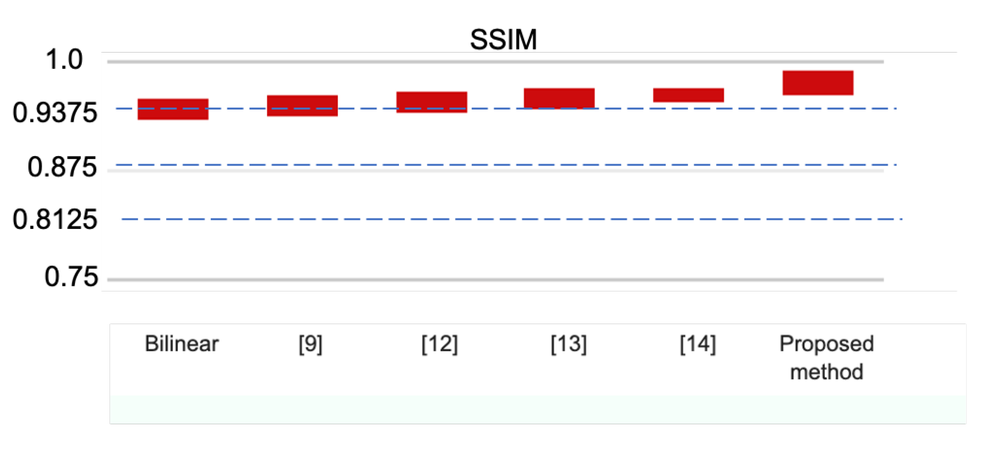
| Method | Bilinear | [9] | [12] | [13] | [14] | Proposed |
|---|---|---|---|---|---|---|
| - | Method | |||||
| Book | 0.872 | 0.881 | 0.887 | 0.891 | 0.925 | 0.943 |
| Car | 0.901 | 0.911 | 0.919 | 0.922 | 0.935 | 0.966 |
| Door | 0.891 | 0.901 | 0.908 | 0.921 | 0.932 | 0.951 |
| Horse | 0.881 | 0.885 | 0.896 | 0.907 | 0.912 | 0.933 |
| Moabit | 0.903 | 0.912 | 0.904 | 0.911 | 0.924 | 0.941 |
| Bullinger | 0.908 | 0.915 | 0.921 | 0.926 | 0.936 | 0.974 |
| Mean | 0.892 | 0.901 | 0.906 | 0.913 | 0.928 | 0.951 |
| Standard Deviation | 0.0139 | 0.0146 | 0.0131 | 0.0134 | 0.0090 | 0.0157 |
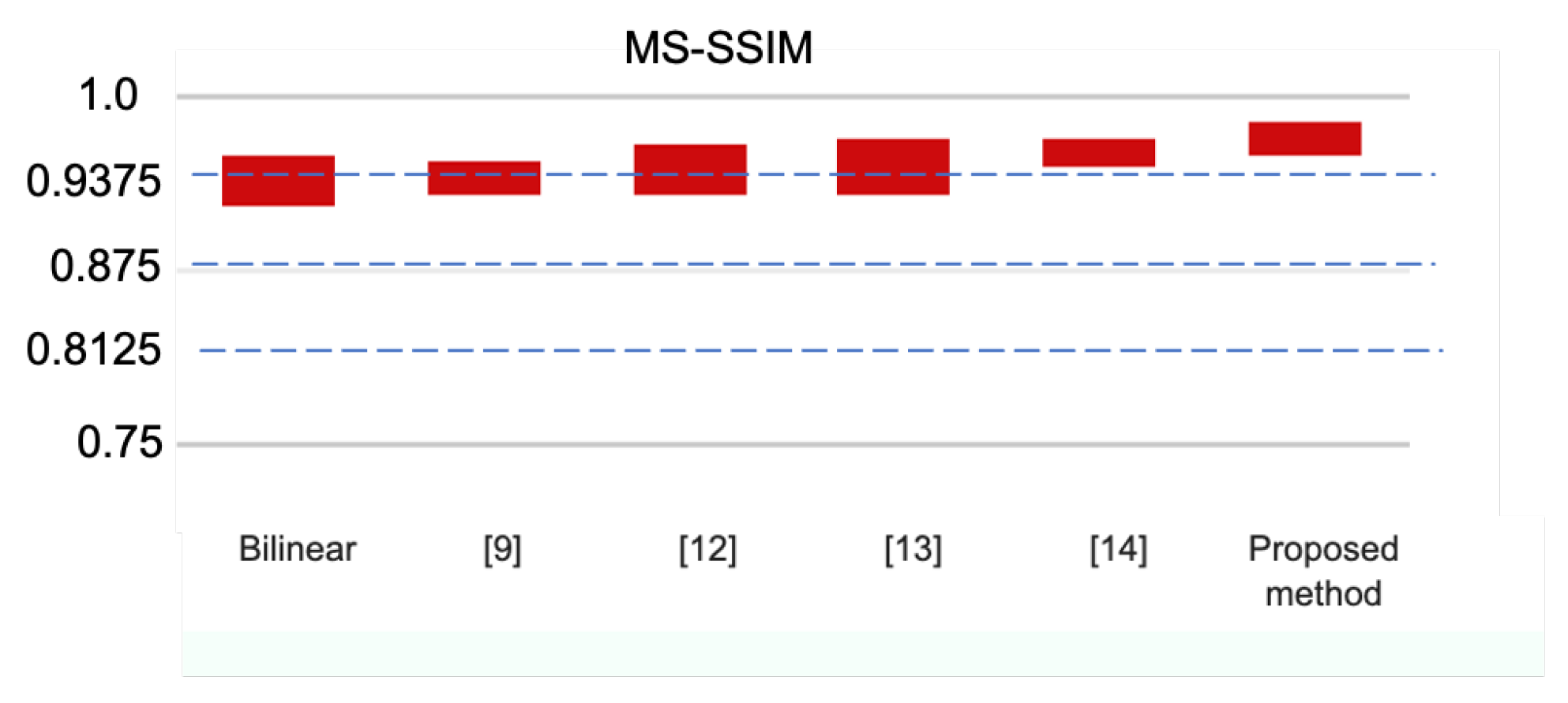
| Method | Bilinear | [9] | [12] | [13] | [14] | Proposed |
|---|---|---|---|---|---|---|
| - | Method | |||||
| Book | 0.842 | 0.873 | 0.879 | 0.882 | 0.915 | 0.955 |
| Car | 0.866 | 0.869 | 0.875 | 0.873 | 0.904 | 0.934 |
| Door | 0.887 | 0.891 | 0.904 | 0.911 | 0.920 | 0.931 |
| Horse | 0.871 | 0.879 | 0.882 | 0.887 | 0.911 | 0.926 |
| Moabit | 0.893 | 0.905 | 0.911 | 0.919 | 0.922 | 0.932 |
| Bullinger | 0.896 | 0.912 | 0.919 | 0.921 | 0.935 | 0.961 |
| Mean | 0.874 | 0.889 | 0.895 | 0.899 | 0.918 | 0.939 |
| Standard Deviation | 0.0204 | 0.0140 | 0.0186 | 0.0206 | 0.0106 | 0.0144 |
| Method | Bilinear | [9] | [12] | [13] | [14] | Proposed |
|---|---|---|---|---|---|---|
| - | Method | |||||
| Book | 0.15 | 10.60 | 39.09 | 1.20 | 1.76 | 1.81 |
| Car | 0.18 | 5.10 | 28.78 | 0.65 | 1.05 | 1.12 |
| Door | 0.25 | 9.76 | 37.09 | 0.91 | 1.49 | 1.15 |
| Horse | 0.31 | 5.28 | 32.36 | 0.86 | 1.55 | 1.59 |
| Moabit | 0.21 | 10.30 | 40.77 | 1.10 | 2.42 | 2.62 |
| Bullinger | 0.16 | 2.94 | 13.82 | 0.31 | 0.60 | 0.69 |
| Mean | 0.21 | 7.33 | 31.99 | 0.84 | 1.47 | 1.50 |
| Standard Deviation | 0.0609 | 3.2822 | 9.9408 | 0.3223 | 0.6206 | 0.6755 |
Publisher’s Note: MDPI stays neutral with regard to jurisdictional claims in published maps and institutional affiliations. |
© 2021 by the authors. Licensee MDPI, Basel, Switzerland. This article is an open access article distributed under the terms and conditions of the Creative Commons Attribution (CC BY) license (https://creativecommons.org/licenses/by/4.0/).
Share and Cite
Van Duc, P.; Tin, P.T.; Le, A.V.; Nhan, N.H.K.; Elara, M.R. Inter-Frame Based Interpolation for Top–Bottom Packed Frame of 3D Video. Symmetry 2021, 13, 702. https://doi.org/10.3390/sym13040702
Van Duc P, Tin PT, Le AV, Nhan NHK, Elara MR. Inter-Frame Based Interpolation for Top–Bottom Packed Frame of 3D Video. Symmetry. 2021; 13(4):702. https://doi.org/10.3390/sym13040702
Chicago/Turabian StyleVan Duc, Phan, Phu Tran Tin, Anh Vu Le, Nguyen Huu Khanh Nhan, and Mohan Rajesh Elara. 2021. "Inter-Frame Based Interpolation for Top–Bottom Packed Frame of 3D Video" Symmetry 13, no. 4: 702. https://doi.org/10.3390/sym13040702
APA StyleVan Duc, P., Tin, P. T., Le, A. V., Nhan, N. H. K., & Elara, M. R. (2021). Inter-Frame Based Interpolation for Top–Bottom Packed Frame of 3D Video. Symmetry, 13(4), 702. https://doi.org/10.3390/sym13040702