
Development of Machine Learning Algorithms for the Determination of the Centre of Mass

 ,
,  ,
,  ,
,  ,
,  and
and 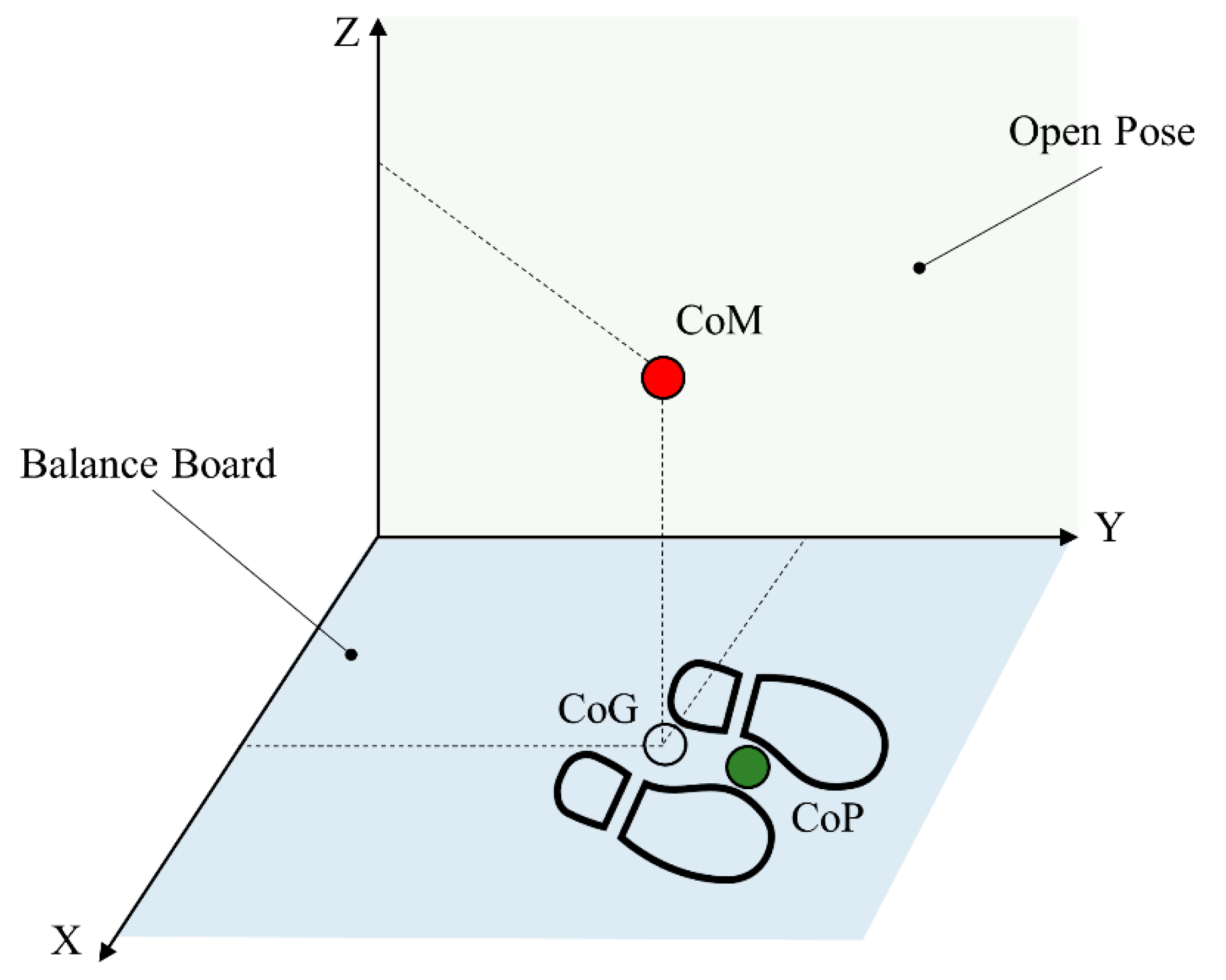
Abstract
1. Introduction
2. Materials and Methods
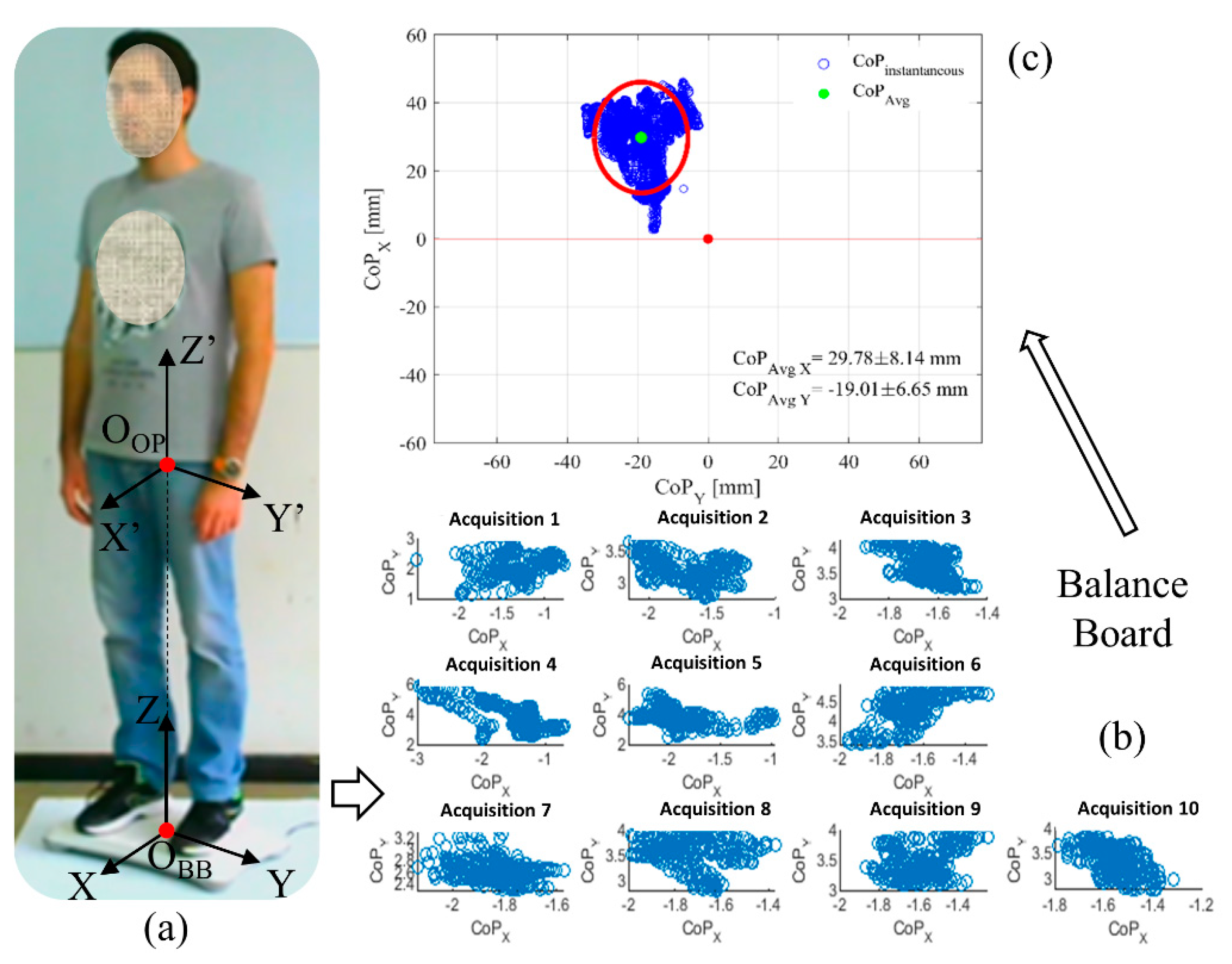
2.1. Wii Balance Board
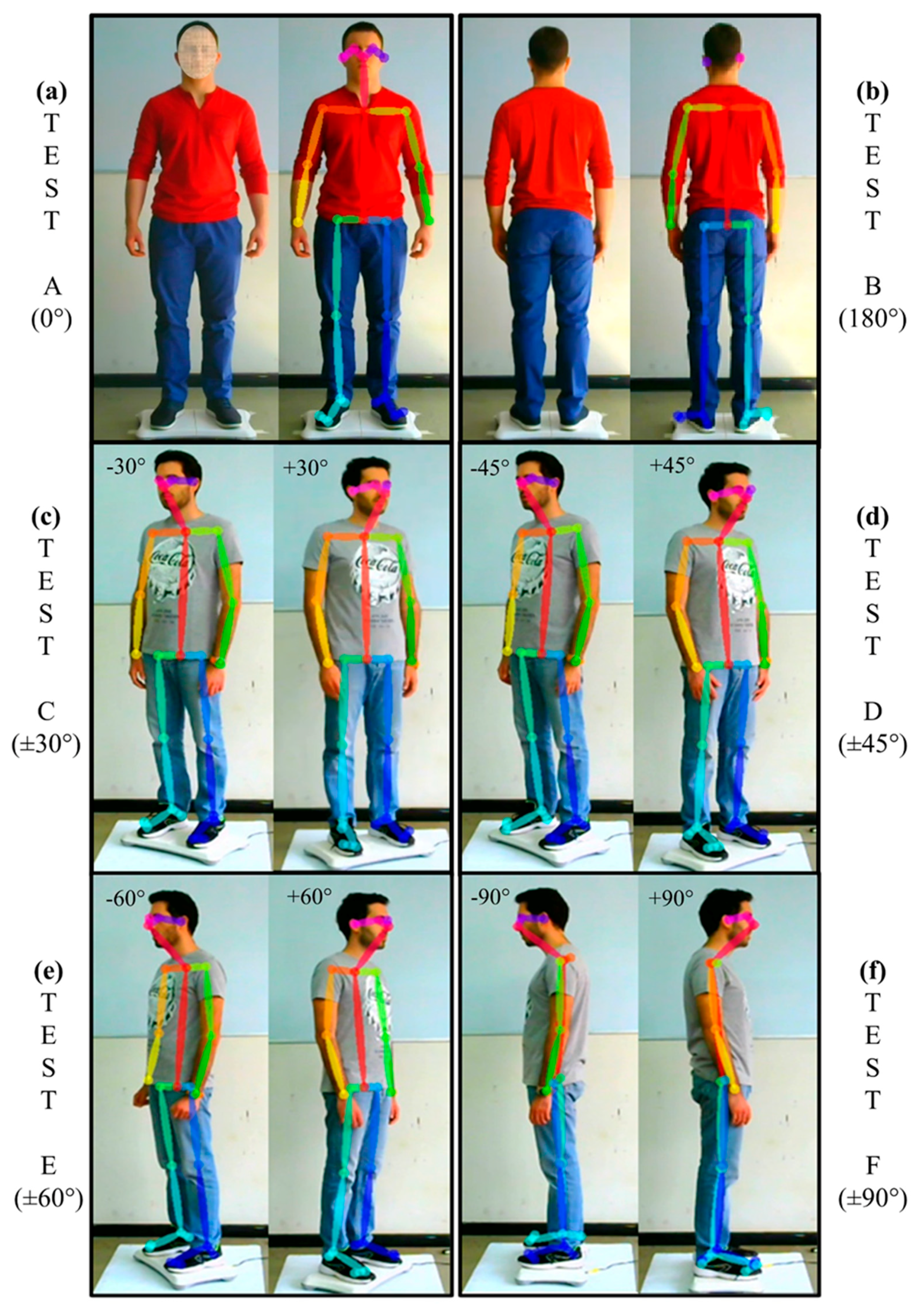
2.2. Video Acquisition
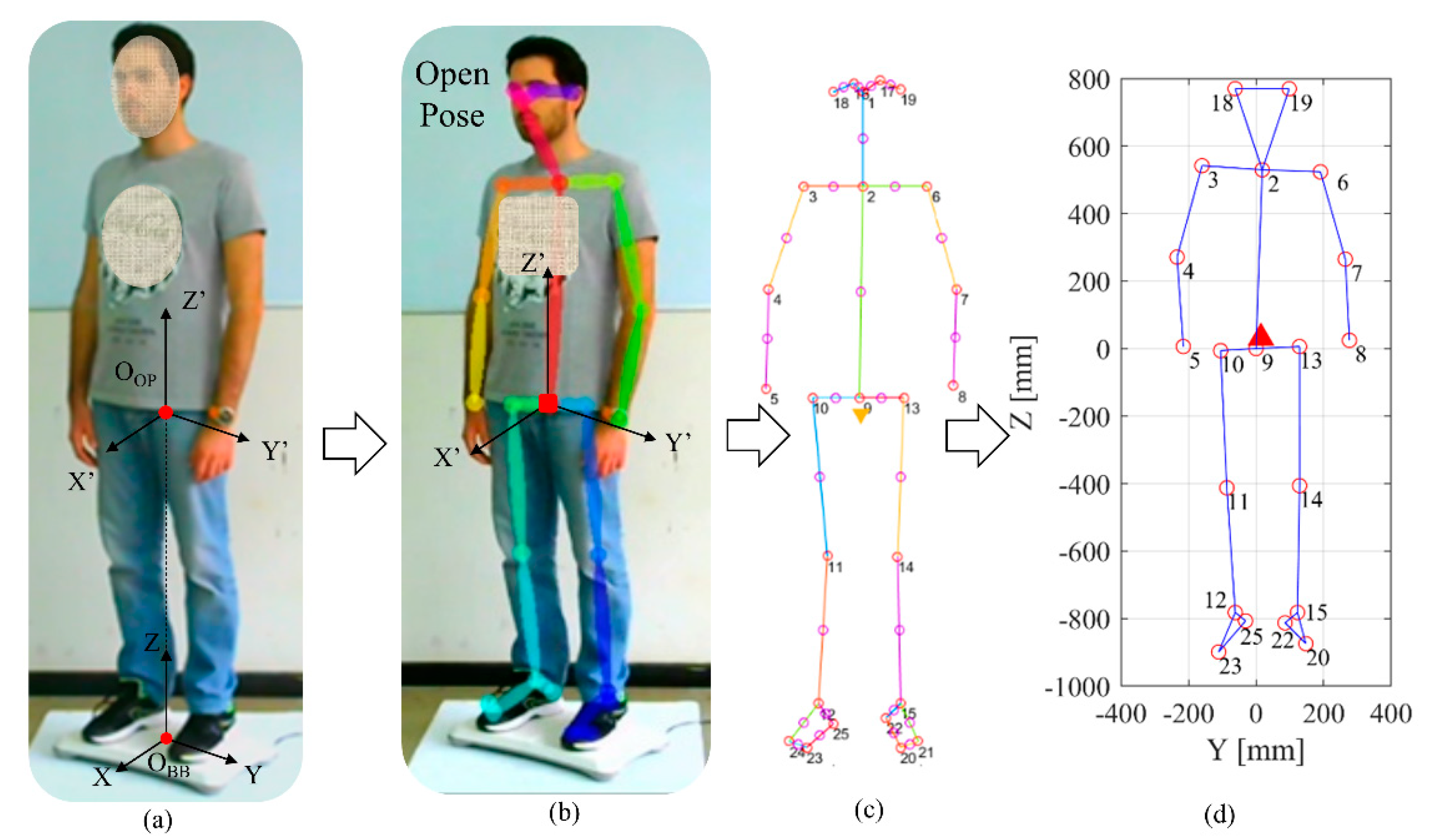
2.3. OpenPose
2.4. Assessment of the Centre of Mass
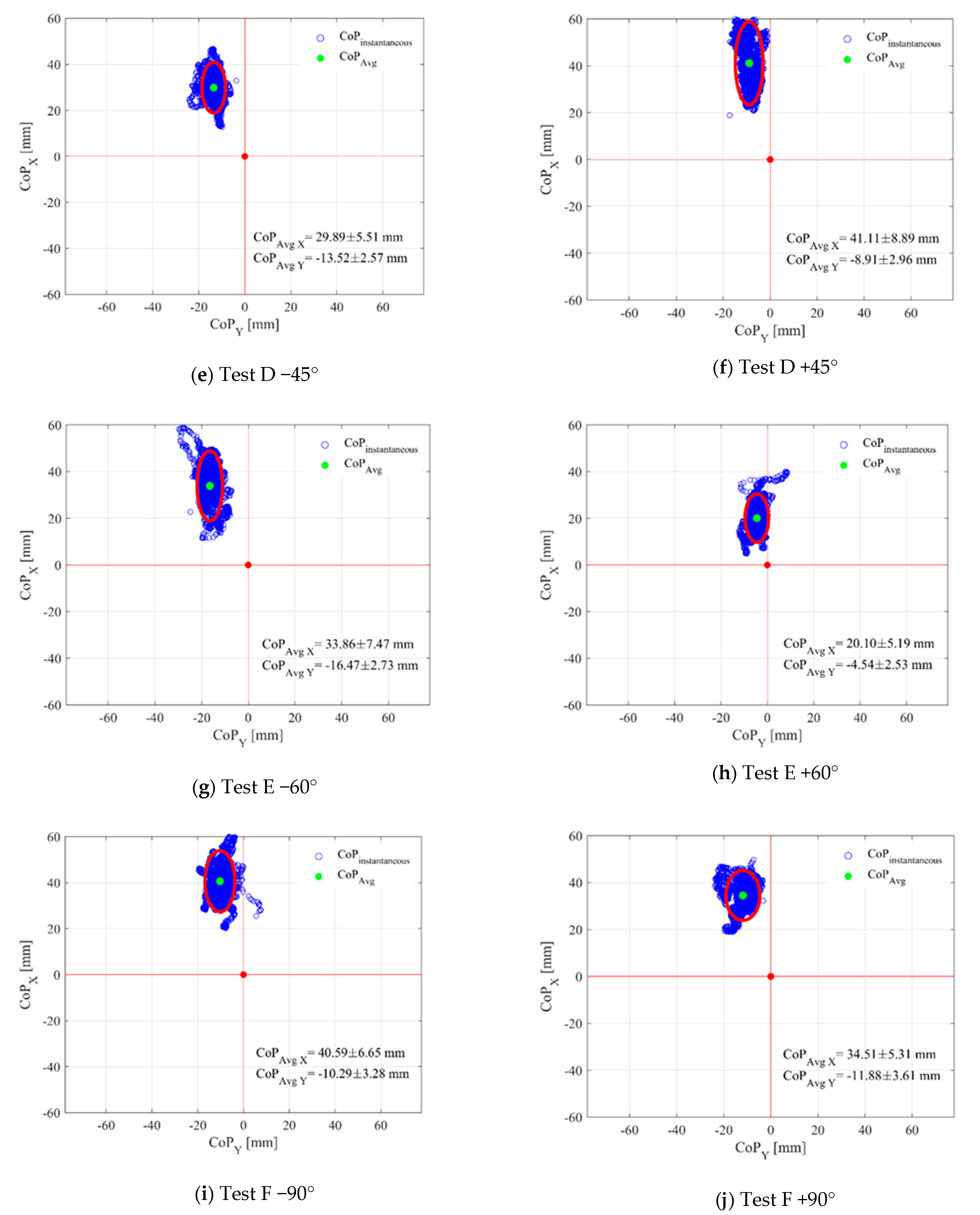
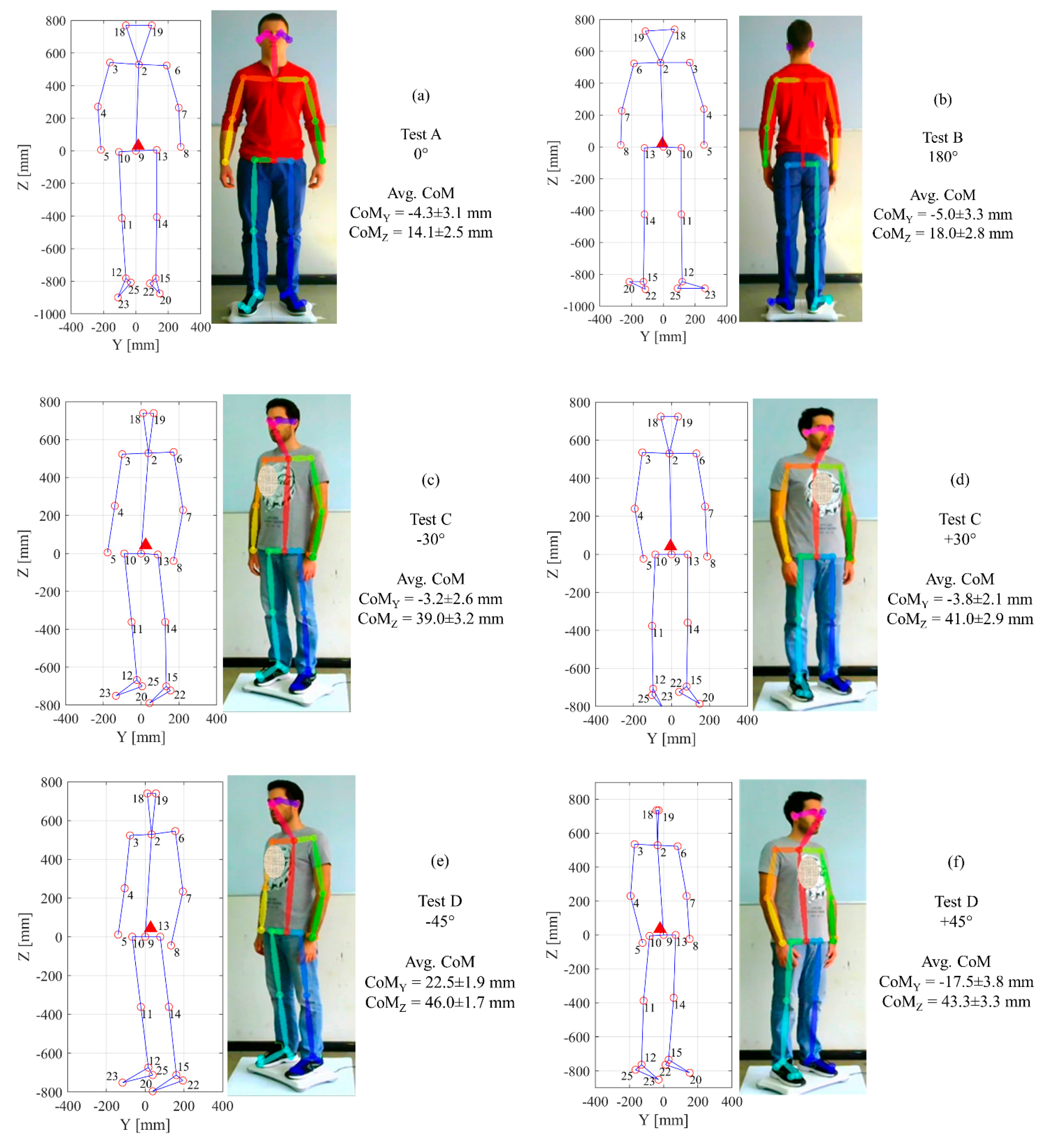
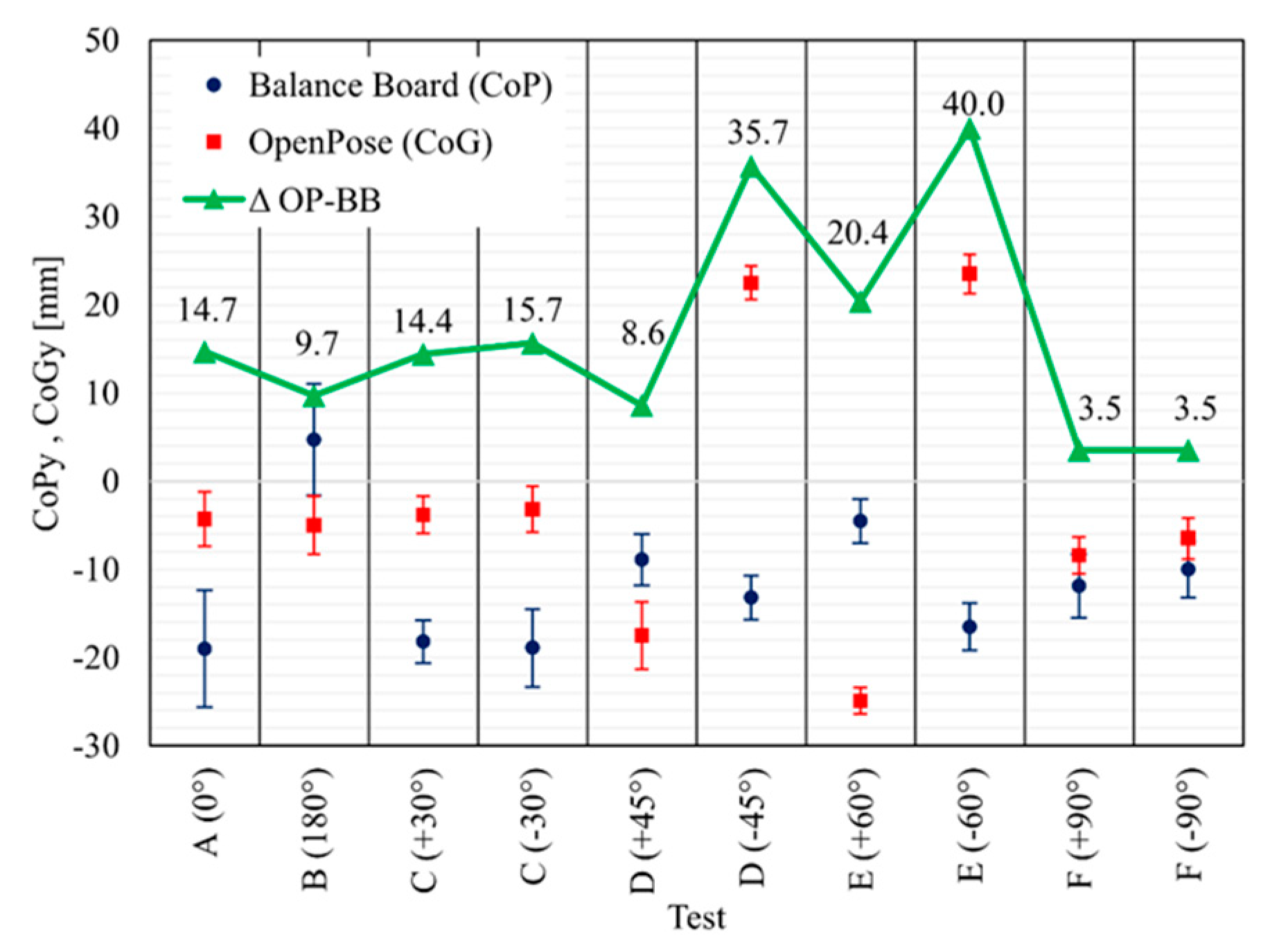
3. Results
4. Conclusions
Author Contributions
Funding
Data Availability Statement
Conflicts of Interest
List of Abbreviations
| CoM | Centre of Mass |
| CoG | Centre of Mass on the Ground |
| CoP | Centre of Pressure |
| OP | OpenPose |
| BB | Nintendo™ Wii Balance Board™ |
| CNN | Convolution Neural Networks |
| MoCap | Motion Capture |
References
- Baker, R. Gait analysis methods in rehabilitation. J. Neuroeng. Rehabil. 2006, 3, 1–10. [Google Scholar] [CrossRef] [PubMed]
- Pawik, Ł.; Wietecki, P.; Leśkow, A.; Pajchert Kozłowska, A.; Żarek, S.; Górski, R.; Pawik, M.; Fink-Lwow, F.; Urbański, W.; Morasiewicz, P. Gait Symmetry Analysis in Patients after Treatment of Pilon Fractures by the Ilizarov Method. Symmetry 2021, 13, 349. [Google Scholar] [CrossRef]
- Deng, Y.; Gao, F.; Chen, H. Angle estimation for knee joint movement based on PCA-RELM algorithm. Symmetry 2020, 12, 130. [Google Scholar] [CrossRef]
- Blaszczyk, J.W.; Prince, F.; Raiche, M.; Hébert, R. Effect of ageing and vision on limb load asymmetry during quiet stance. J. Biomech. 2000, 33, 1243–1248. [Google Scholar] [CrossRef]
- Catena, R.D.; Connolly, C.P.; McGeorge, K.M.; Campbell, N. A comparison of methods to determine center of mass during pregnancy. J. Biomech. 2018, 71, 217–224. [Google Scholar] [CrossRef]
- Daniels, K.A.; Henderson, G.; Strike, S.; Cosgrave, C.; Fuller, C.; Falvey, É. The use of continuous spectral analysis for the assessment of postural stability changes after sports-related concussion. J. Biomech. 2019, 97, 109400. [Google Scholar] [CrossRef]
- Kenneally-Dabrowski, C.; Brown, N.A.; Warmenhoven, J.; Serpell, B.G.; Perriman, D.; Lai, A.K.; Spratford, W. Late swing running mechanics influence hamstring injury susceptibility in elite rugby athletes: A prospective exploratory analysis. J. Biomech. 2019, 92, 112–119. [Google Scholar] [CrossRef] [PubMed]
- Lampe, R.; Mitternacht, J.; Schrödl, S.; Gerdesmeyer, L.; Natrath, M.; Gradinger, R. Influence of orthopaedic-technical aid on the kinematics and kinetics of the knee joint of patients with neuro-orthopaedic diseases. Brain Dev. 2004, 26, 219–226. [Google Scholar] [CrossRef]
- Gonzalez, A.; Hayashibe, M.; Demircan, E.; Fraisse, P. Center of mass estimation for rehabilitation in a multi-contact environment: A simulation study. In Proceedings of the 2013 IEEE International Conference on Systems, Man, and Cybernetics, Manchester, UK, 13–16 October 2013; pp. 4718–4723. [Google Scholar] [CrossRef]
- Yoganandan, N.; Pintar, F.A.; Zhang, J.; Baisden, J.L. Physical properties of the human head: Mass, center of gravity and moment of inertia. J. Biomech. 2009, 42, 1177–1192. [Google Scholar] [CrossRef]
- Catena, R.D.; Chen, S.-H.; Chou, L.-S. Does the anthropometric model influence whole-body center of mass calculations in gait? J. Biomech. 2017, 59, 23–28. [Google Scholar] [CrossRef]
- Durkin, J.L.; Dowling, J.J.; Andrews, D.M. The measurement of body segment inertial parameters using dual energy X-ray absorptiometry. J. Biomech. 2002, 35, 1575–1580. [Google Scholar] [CrossRef]
- Lafond, D.; Duarte, M.; Prince, F. Comparison of three methods to estimate the center of mass during balance assessment. J. Biomech. 2004, 37, 1421–1426. [Google Scholar] [CrossRef]
- Lenzi, D.; Cappello, A.; Chiari, L. Influence of body segment parameters and modeling assumptions on the estimate of center of mass trajectory. J. Biomech. 2003, 36, 1335–1341. [Google Scholar] [CrossRef]
- Munoz, F.; Rougier, P. Estimation of centre of gravity movements in sitting posture: Application to trunk backward tilt. J. Biomech. 2011, 44, 1771–1775. [Google Scholar] [CrossRef] [PubMed]
- Wieczorek, B.; Kukla, M.; Warguła, Ł. The symmetric nature of the position distribution of the human body center of gravity during propelling manual wheelchairs with innovative propulsion systems. Symmetry 2021, 13, 154. [Google Scholar] [CrossRef]
- Hanley, B.; Tucker, C.B. Gait variability and symmetry remain consistent during high-intensity 10,000 m treadmill running. J. Biomech. 2018, 79, 129–134. [Google Scholar] [CrossRef]
- Glazier, P.S.; Mehdizadeh, S. Challenging conventional paradigms in applied sports biomechanics research. Sports Med. 2019, 49, 171–176. [Google Scholar] [CrossRef] [PubMed]
- Al-Juaid, R.; Al-Amri, M. An evaluation of symmetries in ground reaction forces during self-paced single- and dual-task treadmill walking in the able-bodied men. Symmetry 2020, 12, 2101. [Google Scholar] [CrossRef]
- Devise, M.; Rossi, J.; Théveniau, N.; Belli, A. Simple method for measuring center of mass work during field running. J. Biomech. 2019, 97, 109369. [Google Scholar] [CrossRef] [PubMed]
- Morin, J.-B.; Samozino, P.; Murata, M.; Cross, M.R.; Nagahara, R. A simple method for computing sprint acceleration kinetics from running velocity data: Replication study with improved design. J. Biomech. 2019, 94, 82–87. [Google Scholar] [CrossRef]
- Morlier, J.; Mesnard, M. Influence of the moment exerted by the athlete on the pole in pole-vaulting performance. J. Biomech. 2007, 40, 2261–2267. [Google Scholar] [CrossRef]
- Kim, K.J.; Agrawal, V.; Bennett, C.; Gaunaurd, I.; Feigenbaum, L.; Gailey, R. Measurement of lower limb segmental excursion using inertial sensors during single limb stance. J. Biomech. 2018, 71, 151–158. [Google Scholar] [CrossRef]
- Hanley, B.; Bissas, A.; Merlino, S.; Gruber, A.H. Most marathon runners at the 2017 IAAF World Championships were rearfoot strikers, and most did not change footstrike pattern. J. Biomech. 2019, 92, 54–60. [Google Scholar] [CrossRef]
- Clark, R.A.; Bryant, A.L.; Pua, Y.; McCrory, P.; Bennell, K.; Hunt, M. Validity and reliability of the Nintendo Wii Balance Board for assessment of standing balance. Gait Posture 2010, 31, 307–310. [Google Scholar] [CrossRef] [PubMed]
- Goble, D.J.; Cone, B.L.; Fling, B.W. Using the Wii Fit as a tool for balance assessment and neurorehabilitation: The first half decade of “Wii-search”. J. Neuroeng. Rehabil. 2014, 11, 1–9. [Google Scholar] [CrossRef] [PubMed]
- Thomas, S.; Fazakarley, L.; Thomas, P.W.; Collyer, S.; Brenton, S.; Perring, S.; Scott, R.; Thomas, F.; Thomas, C.; Jones, K.; et al. Mii-vitaliSe: A pilot randomised controlled trial of a home gaming system (Nintendo Wii) to increase activity levels, vitality and well-being in people with multiple sclerosis. BMJ Open 2017, 7, 1–16. [Google Scholar] [CrossRef]
- Wall, T.; Feinn, R.; Chui, K.; Cheng, M.S. The effects of the Nintendo™ Wii Fit on gait, balance, and quality of life in individuals with incomplete spinal cord injury. J. Spinal Cord Med. 2015, 38, 777–783. [Google Scholar] [CrossRef] [PubMed][Green Version]
- Young, W.; Ferguson, S.; Brault, S.; Craig, C. Assessing and training standing balance in older adults: A novel approach using the ‘Nintendo Wii’ Balance Board. Gait Posture 2011, 33, 303–305. [Google Scholar] [CrossRef] [PubMed]
- Gil-Gómez, J.-A.; Lloréns, R.; Alcañiz, M.; Colomer, C. Effectiveness of a Wii balance board-based system (eBaViR) for balance rehabilitation: A pilot randomized clinical trial in patients with acquired brain injury. J. Neuroeng. Rehabil. 2011, 8, 30. [Google Scholar] [CrossRef]
- GonçalvesG, B.; Leite, M.A.A.; Orsini, M.; Pereira, J.S. Effects of using the Nintendo Wii Fit Plus platform in the sensorimotor training of gait disorders in Parkinson’s disease. Neurol. Int. 2014, 6, 6–8. [Google Scholar] [CrossRef]
- Mhatre, P.V.; Vilares, I.; Stibb, S.M.; Albert, M.V.; Pickering, L.; Marciniak, C.M.; Kording, K.; Toledo, S. Wii Fit balance board playing improves balance and gait in Parkinson disease. PM&R 2013, 5, 769–777. [Google Scholar] [CrossRef]
- Miller, C.A.; Hayes, D.M.; Dye, K.; Johnson, C.; Meyers, J. Using the Nintendo Wii Fit and body weight support to improve aerobic capacity, balance, gait ability, and fear of falling: Two case reports. J. Geriatr. Phys. Ther. 2012, 35, 95–104. [Google Scholar] [CrossRef] [PubMed]
- Krishnan, C.; Washabaugh, E.P.; Seetharaman, Y. A low cost real-time motion tracking approach using webcam technology. J. Biomech. 2015, 48, 544–548. [Google Scholar] [CrossRef]
- Cronin, N.J.; Rantalainen, T.; Ahtiainen, J.P.; Hynynen, E.; Waller, B. Markerless 2D kinematic analysis of underwater running: A deep learning approach. J. Biomech. 2019, 87, 75–82. [Google Scholar] [CrossRef]
- Capecci, M.; Ceravolo, M.G.; Ferracuti, F.; Grugnetti, M.; Iarlori, S.; Longhi, S.; Romeo, L.; Verdini, F. An instrumental approach for monitoring physical exercises in a visual markerless scenario: A proof of concept. J. Biomech. 2018, 69, 70–80. [Google Scholar] [CrossRef] [PubMed]
- Clark, R.A.; Mentiplay, B.F.; Hough, E.; Pua, Y.H. Three-dimensional cameras and skeleton pose tracking for physical function assessment: A review of uses, validity, current developments and Kinect alternatives. Gait Posture 2019, 68, 193–200. [Google Scholar] [CrossRef]
- Tanaka, R.; Takimoto, H.; Yamasaki, T.; Higashi, A. Validity of time series kinematical data as measured by a markerless motion capture system on a flatland for gait assessment. J. Biomech. 2018, 71, 281–285. [Google Scholar] [CrossRef] [PubMed]
- González, A.; Hayashibe, M.; Bonnet, V.; Fraisse, P. Whole body center of mass estimation with portable sensors: Using the statically equivalent serial chain and a kinect. Sensors 2014, 14, 16955–16971. [Google Scholar] [CrossRef]
- Cao, Z.; Simon, T.; Wei, S.-E.; Sheikh, Y. Realtime multi-person 2D pose estimation using part affinity fields. In Proceedings of the 2017 IEEE Conference on Computer Vision and Pattern Recognition (CVPR), Honolulu, HI, USA, 21–26 July 2017; pp. 1302–1310. [Google Scholar]
- Okugawa, Y.; Kubo, M.; Sato, H.; Duc Viet, B. Evaluation for the Synchronization of the Parade with OpenPose. Proc. Int. Conf. Artif. Life Robot. 2019, 24, 443–446. [Google Scholar] [CrossRef]
- Qiao, S.; Wang, Y.; Li, J. Real-time human gesture grading based on OpenPose. In Proceedings of the 2017 10th International Congress on Image and Signal Processing, BioMedical Engineering and Informatics (CISP-BMEI), Shanghai, China, 14–16 October 2017; pp. 1–6. [Google Scholar]
- Liaqat, S.; Dashtipour, K.; Arshad, K.; Assaleh, K.; Ramzan, N. A hybrid posture detection framework: Integrating machine learning and deep neural networks. IEEE Sens. J. 2021, 1. [Google Scholar] [CrossRef]
- Masani, K.; Vette, A.H.; Kouzaki, M.; Kanehisa, H.; Fukunaga, T.; Popovic, M.R. Larger center of pressure minus center of gravity in the elderly induces larger body acceleration during quiet standing. Neurosci. Lett. 2007, 422, 202–206. [Google Scholar] [CrossRef] [PubMed]
- Bailey, R.C.; Halls, H.C. Estimate of confidence in paleomagnetic directions derived from mixed remagnetization circle and direct observational data. J. Geophys. Geophys. 1984, 54, 174–182. [Google Scholar]
- Clerval, J.; Lacombe-Delpech, R.; Adolphe, M.; Zagrodny, B.; Kirchof, Z. Center of mass of human’s body segments. Mech. Mech. Eng. 2017, 21, 485–497. [Google Scholar]
- Croskey, M.I.; Dawson, P.M.; Luessen, A.C.; Marohn, I.E.; Wright, H.E. The height of the center of gravity in man. Am. J. Physiol. Content 1922, 61, 171–185. [Google Scholar] [CrossRef]


Publisher’s Note: MDPI stays neutral with regard to jurisdictional claims in published maps and institutional affiliations. |
© 2021 by the authors. Licensee MDPI, Basel, Switzerland. This article is an open access article distributed under the terms and conditions of the Creative Commons Attribution (CC BY) license (http://creativecommons.org/licenses/by/4.0/).
Share and Cite
D’Andrea, D.; Cucinotta, F.; Farroni, F.; Risitano, G.; Santonocito, D.; Scappaticci, L. Development of Machine Learning Algorithms for the Determination of the Centre of Mass. Symmetry 2021, 13, 401. https://doi.org/10.3390/sym13030401
D’Andrea D, Cucinotta F, Farroni F, Risitano G, Santonocito D, Scappaticci L. Development of Machine Learning Algorithms for the Determination of the Centre of Mass. Symmetry. 2021; 13(3):401. https://doi.org/10.3390/sym13030401
Chicago/Turabian StyleD’Andrea, Danilo, Filippo Cucinotta, Flavio Farroni, Giacomo Risitano, Dario Santonocito, and Lorenzo Scappaticci. 2021. "Development of Machine Learning Algorithms for the Determination of the Centre of Mass" Symmetry 13, no. 3: 401. https://doi.org/10.3390/sym13030401
APA StyleD’Andrea, D., Cucinotta, F., Farroni, F., Risitano, G., Santonocito, D., & Scappaticci, L. (2021). Development of Machine Learning Algorithms for the Determination of the Centre of Mass. Symmetry, 13(3), 401. https://doi.org/10.3390/sym13030401