Abstract
Excessive recoil severely restricts the loading of high-power traditional guns on modern vehicles. To reduce the recoil without breaking the continuous firing mode and reducing the projectile velocity, a recoil reduction method that controls the lateral ejecting of propellant gas by a piston was proposed. The recoil reduction device is symmetric about the barrel axis. First, a one-dimensional two-phase flow model of interior ballistic during the gun firing cycle was established. Next, the MacCormack scheme was used to simulate, and the piston motion was gained. Then the propagation of the rarefaction wave in the barrel was presented. Finally, the propulsion difference between the piston-controlled gun and the traditional gun was discussed. The results showed that the recoil momentum was reduced by 31.80%, and the muzzle velocity was decreased by just 1.30% under the reasonable matching of structural parameters.
1. Introduction
In modern war, power increase and maneuverability improvement are the development trend for traditional guns. However, they conflict with each other. The propellant gas produces recoil force on the gun system while pushing the projectile to accelerate. With the projectile velocity increasing, heavier mount is needed to absorb the recoil force. Especially for guns on vehicles and aircrafts, excessive recoil will cause these carrying platforms to vibrate violently. Therefore, recoil reduction is the key to solve the conflict. To reduce the recoil, many techniques have been developed, including soft recoil [1] and magnetorheological fluid technology [2,3]. However, these techniques lead to problems, such as low reliability and complex structure. Moreover, the recoil reduction efficiency is limited.
Considering that the energy of the propellant gas venting from the muzzle usually accounts for over 40% of the total propellant energy, numerous studies have been done on reducing the recoil by using propellant gas energy. The muzzle brake [4,5] is a typical example. However, its efficiency is limited. Kathe [6,7] proposed a concept of rarefaction wave gun to reduce the recoil by venting propellant gas through the breech. Nevertheless, this method breaks the continuous firing mode of a traditional gun, which restricts its development in engineering application. Liao [8], Chen [9], and Cheng [10] studied the reversely jet low recoil gun, which vents propellant gas through the orifice in the side wall of the barrel. This gun can achieve continuous firing, but the projectile base pressure drops once propellant gas vents through the orifice, resulting in a decrease of the muzzle velocity. Zhang [11], Wang [12], Zhang [13,14,15], and Coffee [16] studied the propulsion process of the rarefaction wave gun based on two-phase flow theory. Zhang [15] proposed a front orifice rarefaction wave gun. However, he ignored the control device movement, so the exact recoil reduction efficiency could not be obtained. Xiao [17] studied the launching process of a time-delay nozzle device. Due to the use of a lumped-parameter model [18], it is difficult to capture the rarefaction wave movement, so the accurate opening time of the orifice could not be obtained.
At present, the propulsion process of guns is often simulated based on two-phase flow theory [19,20,21,22,23]. Monreal [24] established a one-dimensional two-phase interior ballistics model for a gun based on the theoretical and experimental study of porous propellant combustion. Menshov [25] adopted a two-dimensional axisymmetric nonequilibrium gas–solid two-phase interior ballistics model to analyze the flow field in the barrel, considering the combustion of inhomogeneously distributed propellant. Hu [26] proposed a method based on the Riemann problem to improve the simulation of propellant combustion. Cheng [27,28] and Cao [29,30] proposed a two-fluid model with two moving boundaries to study the propulsion process of a two-stage combustion gun. However, the above studies focus on the flow characteristics of the propellant gas in a straight tube, excluding the analysis of the flow in a tube with porous channels.
In this work, a recoil reduction method, which controls the lateral ejecting of propellant gas by a piston-spring device, is proposed for a 30-mm gun. As the gun barrel presented here is equipped with a piston cavity and an exhaust pipe, the propulsion process of the gun is quite different from that of a traditional gun. First, the propulsion process of the gun is numerically simulated based on two-phase interior ballistics theory. Next, the piston motion is analyzed. Then the flow characteristics of the propellant gas in the barrel and the additional channels are studied. Finally, the changes in the muzzle velocity and the recoil are discussed.
2. Principle of the Piston-Controlled Gun
The schematic of the gun with side to rear jet controlled by piston motion is shown in Figure 1. To avoid the imbalance of lateral force on the barrel, the recoil reduction device is symmetric about the barrel axis, and just one side is displayed in Figure 1. In the side wall of the barrel, there is a vent which is near the breech and in front of the chamber. Initially, the barrel vent is blocked by the piston under the action of spring force, as shown in Figure 1a. After the projectile reaches the barrel vent, the propellant gas in the barrel flows into the piston cavity and pushes the piston to move upwards. Only when the piston travels a specified distance can the rear spray channel be opened, as shown in Figure 1b. Then the propellant gas flows through the exhaust pipe and finally ejects from the divergent nozzle at high speed, producing a forward thrust to reduce the recoil momentum. When the rear spray channel is opened, the rarefaction wave is generated due to the pressure drop at the barrel vent, and travels towards the projectile base and the breech. The pressure reduces where the rarefaction wave reaches. However, the projectile base pressure does not drop immediately because the projectile has arrived at a position far from the barrel vent. Thus, it is possible to make the rarefaction wave unable to catch the projectile until the muzzle under the reasonable matching of the parameters, such as the barrel vent size and the spring stiffness. The piston will be reset under the action of the spring force after the propulsion process is over, so the continuous firing of the gun is not affected. This gun is called the piston-controlled gun in the following paragraphs.
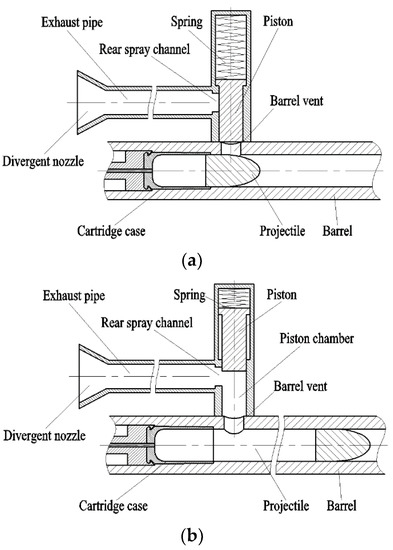
Figure 1.
Structure diagram of the piston-controlled gun. (a) Gas port in closed position; (b) Gas port in opened position.
3. Theoretical Models
3.1. Assumptions of the Model
To simplify the problem, the following assumptions [5] are made. The assumptions have been practiced and proven in theoretical studies and the numerical calculations of internal ballistics for weapons [5,14]. They will bring errors to the calculation in this paper, but these errors could be accepted.
- (1)
- Each phase is a continuum in line with the assumption of two-fluid model.
- (2)
- One-dimensional unsteady flow is considered in the barrel, the piston cavity, and the exhaust pipe.
- (3)
- The viscous dissipation of propellant gas and its heat loss to the wall are ignored.
- (4)
- The propellant gas flow is treated as an isentropic flow when the propellant gas flows through a bifurcated tube or elbow.
3.2. The Governing Equations of the Two-Phase Flow in the Barrel
The governing equations of the two-phase flow model in the barrel include the mass conservation equations of the gas and solid phase, the momentum conservation equations of the gas and solid phase, and the energy conservation equation of the gas phase. The energy transfer for the solid phase was considered in the solid temperature equation [14]. According to the change of the propellant gas flow characteristics after the projectile reaches the barrel vent, the equations are as follows in a conservative vector form.
Among these formulas,
where A is the cross-section area of the barrel, ρg and ρp are the gas and solid density, ug and up are the gas and solid velocity, eg and ep are the gas and solid internal energy, φ is the porosity, p is the pressure, τp and fs are the intergranular stress and interphase drag, Qs is the interphase heat transfer, mc is the gas generation rate of the solid propellant per unit volume, mign is the gas generate rate of the ignition powder per unit volume, uign is the velocity of the ignition powder, Hign is the enthalpy of the ignition powder, mgb1 and mpb1 are the mass flow rate of the gas and solid phase out of the barrel from the barrel vent per unit volume, ugb1 and upb1 are the velocity of the gas and solid phase flowing through the barrel vent, ρgb, pb, and egb are the density, pressure, and internal energy of the gas phase flowing through the barrel vent.
The J term in Equation (1) only works in the domain corresponding to the barrel vent. The constitutive equations needed to close the above governing equations, such as the interphase drag and the interphase heat transfer, can be found in [14,18].
3.3. Dynamic Model of Gas–Solid Coupling in the Piston Cavity
After propellant gas flows into the piston cavity through the barrel vent, the piston moves under the action of the propellant gas pressure, the spring resistance, and the friction resistance. The equations about the piston motion are as follows.
where vh, xh, and mh are the velocity, displacement, and mass of the piston, phd is the pressure at the piston base, Sh is the cross-section area of the piston cavity, F0 is the spring preload, kh is the spring stiffness, Fv is the friction force between the piston and the piston cavity.
The governing equations of the two-phase flow model in the piston cavity are similar to those in the barrel. According to the change of the propellant gas flow characteristics after the rear spray channel is enabled, the equations are as follows in a conservative vector form.
Among these formulas, the terms in Uh, Fh, Hh, and Jh are similar to those in Equation (1).
3.4. The Governing Equations of Two-Phase Flow in the Exhaust Pipe
The exhaust pipe is simplified as a straight pipe starting from the rear spray channel. The governing equations of the two-phase flow model in the exhaust pipe is similar to those in the piston cavity.
Among these formulas, the terms in Equation (6) are similar to those in Equation (5).
3.5. Gas Flow Model at the Barrel Vent and Rear Spray Channel
According to the above assumptions, the flow of the propellant gas through the barrel vent can be regarded as an isentropic flow [5]. Based on the ratio of the pressure at the barrel vent to the pressure at the piston cavity entrance, there are four flow states through the barrel vent, namely, forward critical flow, forward noncritical flow, reverse noncritical flow, and reverse critical flow. The related equations can be found in [5]. As the nozzle exit is connected to the atmosphere, the gas flow state of the propellant gas through the rear spray channel can be divided into two types, namely, forward critical flow and forward noncritical flow.
3.6. Calculation of the Recoil Reduction Efficiency
The recoil reduction effect of the buffer devices, such as the muzzle brake, was not considered in this work. The formulas for calculating the resultant force and the recoil momentum of the gun body can be found in [5]. The recoil reduction efficiency is defined as follows.
where Io is the recoil momentum of the gun without nozzle, Ir is the recoil momentum of the gun with nozzle, Ip is the momentum imparted to the gun system by the gas ejecting from the nozzle.
4. Numerical Method
4.1. Difference Scheme
The governing equations above were discretized by the MacCormack scheme [16], which is carried out by two steps, namely the predictor and corrector step.
4.2. Boundary Conditions
The boundary conditions were different at different stages of the propulsion process. The nozzle exit and muzzle exit were taken as the free outlet boundary, which means a fixed outlet pressure was held for the subsonic flow, and the extrapolated condition for the supersonic flow. The reflective boundary was used at all walls of the domain, even if the projectile began to move. Once the projectile moves, the computational domain expands, and the length of the cell near the projectile base increases. When the cell length reached a given limit, the cell near the projectile base was split, and a new cell was added. The equation about the projectile movement can be found in [14]. The method that dealt with the piston movement was similar.
In summary, the solution procedure is in Figure 2.

Figure 2.
Solution procedure.
Where xd is the projectile displacement, Lb and Lr are the location of the barrel vent and the rear spray channel, pd is the projectile base pressure, Δx2 is the length of the cell near the projectile base, ts is setting time, mgb2 and mpb2 are the mass flow rate of the gas and solid phase into the piston cavity from the barrel vent per unit volume, mgr1 and mpr1 are the mass flow rate of the gas and solid phase out of the piston cavity from the rear spray channel per unit volume, mgr2 and mpr2 are the mass flow rate of the gas and solid phase into the exhaust pipe from the rear spray channel per unit volume.
5. Results and Discussion
5.1. Validation
The virtual AGARD (Advisory Group for Aerospace Research and Development) gun model was used to test our codes, and its parameters can be found in [7,15]. The results from our codes are in Figure 3. The results based on the published codes can be found in [7,15,18]. The data are in Table 1. The results from our codes are in good agreement with the expected ones, as shown in Table 1. The difference between these codes is caused by the submodels, such as the intergranular stress and interphase drag.
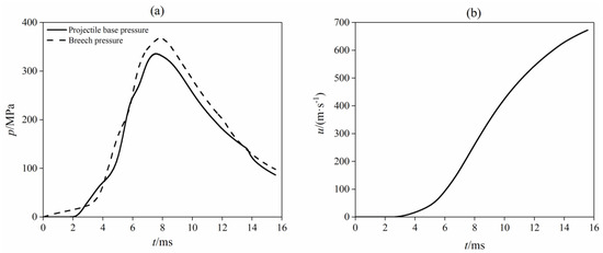
Figure 3.
Simulation of the AGARD gun: (a) pressure at projectile base and breech, (b) projectile velocity.

Table 1.
Numerical results.
5.2. Decision of the Opening Time of the Rear Spray Channel
Based on a traditional 30-mm gun, the piston-controlled gun was transformed by designing a new barrel, as shown in Figure 1. The known parameters are in Table 2. The opening time of the rear spray channel is controlled by the piston. It can be seen from Equation (4) that the piston movement is mainly determined by the parameters, such as the barrel vent size and the spring stiffness. However, these parameters are mutually restrictive. Besides, the flow fields in the barrel, piston cavity, and exhaust pipe are coupled after the rear spray channel is opened, so the relationship between these parameters is complicated and nonlinear. Therefore, it is difficult to derive an analytical expression to solve this relationship. The reasonable match of these parameters could only be obtained by numerous calculations. Taking the criterion that muzzle velocity loss is within 2%, a set of reasonable parameter matches was obtained, as shown in Table 3. The values of the above parameters refer to only one recoil reduction device.

Table 2.
Known parameters.

Table 3.
Calculation parameters.
5.3. Flow Field in the Piston Cavity
The high-pressure propellant gas flowed into the piston cavity after the projectile reached the barrel vent, so the pressure at the piston base increased sharply at 3.23 ms, as shown in Figure 4. However, the piston started to move, pushed by the propellant gas, so the pressure at the piston base reached the peak at 3.38ms and then decreased. At 4.34 ms, the rear spray was conducted due to the piston motion, as shown in Figure 5. Then the propellant gas flowed into the exhaust pipe and was ejected from the nozzle. Therefore, the pressure at the piston base dropped sharply. At 5.38 ms, the piston reached the top and stopped here, so the pressure increased slightly. At 7.42 ms, the pressure at piston base became lower than the spring resistance, so the piston began to reset. The rear spray channel began to be closed at 13.45 ms and became fully closed at 13.96 ms.
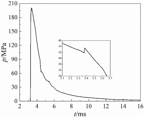
Figure 4.
Pressure at piston base.
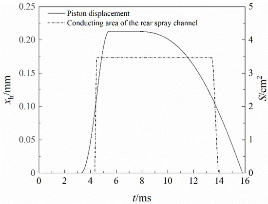
Figure 5.
Time histories of piston location and conducting area of rear spray channel.
The piston returned to its initial position within 16 ms. Therefore, the proposed method does not break the continuous firing mode, because the firing rate of a traditional single-barrel gun does not exceed 1000 r/min and it takes at least 60 ms to finish the firing cycle.
5.4. Rarefaction Wave Front Propagation
When the rear spray channel was opened, a large amount of propellant gas in the barrel flowed into the piston cavity, resulting in a sudden decrease of pressure at the barrel vent. Then the effect of the pressure drop travelled towards the breech and the projectile base in the form of continuous rarefaction waves. The movement characteristics of the projectile and the rarefaction wave front towards the projectile base are shown in Figure 6 and Figure 7. The rarefaction wave was produced at the barrel vent at 4.46 ms, and then travelled towards the projectile base and the breech. Meanwhile, the projectile was 0.86 m away from the barrel vent. The velocity of the projectile and the rarefaction wave both increased monotonically. However, the velocity of the rarefaction wave was higher than that of the projectile. Therefore, the rarefaction wave caught the projectile at 1.28 ms after the rarefaction wave was produced. In the meantime, the projectile just reached the muzzle exit.
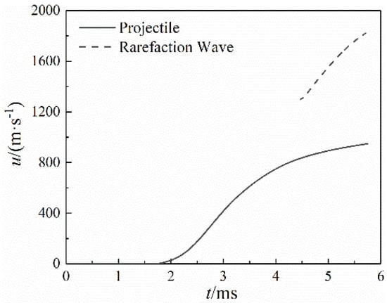
Figure 6.
Velocity of projectile and rarefaction wave front.
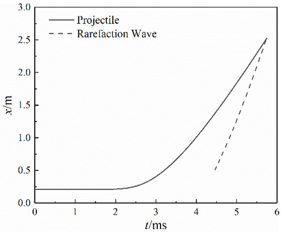
Figure 7.
Position of projectile and rarefaction wave front.
5.5. Flow Field in the Barrel
The comparisons of the pressure in the barrel of the two guns are shown in Figure 8 and Figure 9. Figure 9 displays the projectile base pressure during the interior ballistics period, and displays the muzzle pressure during the after-effect period. The rarefaction wave reached the breech and the projectile base at 5.08 and 5.74 ms, respectively. However, the projectile base pressure of the piston-controlled gun declined at 3.23 ms because the propellant gas in the barrel immediately flowed into the piston cavity when the projectile reached the barrel vent, as shown in Figure 9. Besides, it dropped a little and oscillated slightly because the piston cavity was closed from 3.23 to 4.34 ms and there was both positive and reverse flow between the barrel and the piston cavity during this period. After the rarefaction wave caught the projectile at the muzzle exit, the muzzle pressure of the piston-controlled gun reduced significantly compared with that of the traditional gun.
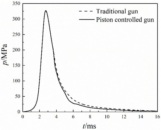
Figure 8.
Breech pressure comparison of two guns.
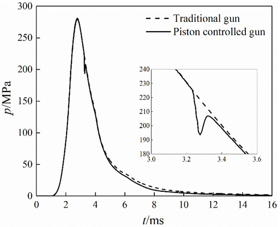
Figure 9.
Projectile/muzzle pressure comparison of two guns.
Similarly, the breech pressure of the piston-controlled gun started to reduce at 3.62 ms instead of 5.08 ms, as shown in Figure 8. The projectile reached the barrel vent at 3.23 ms, and then a rarefaction wave traveled towards the breech and arrived at the breech at 3.62 ms. However, the breech pressure of the piston-controlled gun dropped slightly at this time, but dropped significantly at 5.08 ms. The reasons are as follows. The pressure drop at the barrel vent at 3.23 ms was low, so the rarefaction wave intensity was also low. Thus, the pressure drop at the breech at 3.62 ms was small. The rear spray channel was opened at 4.34 ms, so the pressure drop at the barrel vent was higher, and the rarefaction wave intensity was higher. Therefore, the pressure drop at the breech was higher.
The projectile base pressure of the piston-controlled gun was almost the same as that of the traditional gun, although some propellant gas was ejected from the barrel during the propulsion process. Therefore, the velocity–time curve of the projectile of the two guns was not much different, as shown in Figure 10. Nevertheless, the influence of the barrel vent on the projectile velocity could still be seen. Compared with the traditional gun, the muzzle velocity of the piston-controlled gun reduced from 960.0 to 947.5 m/s, a decrease of 1.30%.
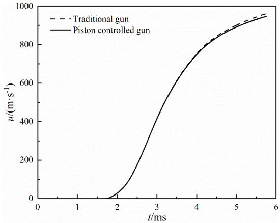
Figure 10.
Velocity comparison of two guns.
5.6. Flow Field in the Exhaust Pipe
Figure 11 and Figure 12 show the pressure and gas velocity distribution along the exhaust pipe axis at four moments after igniting: 0.24 ms after the rear spray channel was opened (4.58 ms after igniting), 0.43 ms after the rear spray channel was fully opened (4.91 ms after igniting), the moment when the projectile exited the muzzle (5.74 ms after igniting), 0.34 ms after the fifth moment (6.08 ms after igniting). Here we define that mark “0” of x-coordinate denotes the rear spray channel, and the nozzle exit is rightward. As can be seen from Figure 11 and Figure 12, a rapid increase of pressure and gas velocity occurred at the entrance of the exhaust pipe at 4.58 ms because the rear spray channel was opened and the propellant gas flowed into the exhaust pipe at high speed. Meanwhile, the propellant gas did not fill the whole pipe. After 4.91 ms, the propellant gas filled the whole pipe and expanded in the pipe, so the propellant gas velocity increased continuously. In the divergent nozzle, the high-pressure propellant gas further expanded and accelerated, thus gaining a greater impulse.
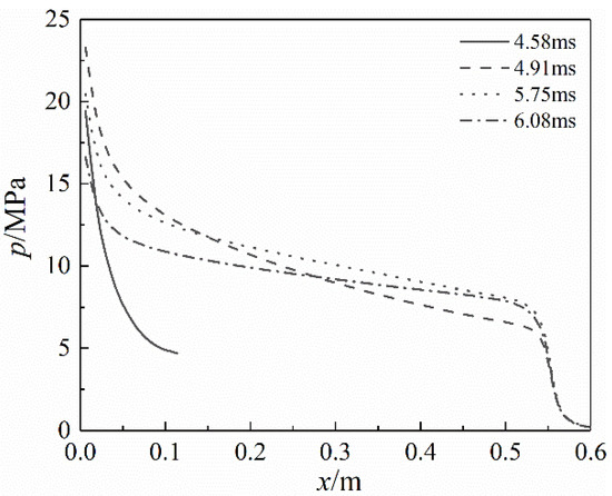
Figure 11.
Pressure distribution along the exhaust pipe axis.
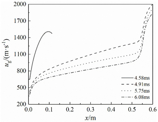
Figure 12.
Gas phase velocity distribution along the exhaust pipe axis.
5.7. Analysis of the Recoil Reduction Efficiency
Here we define the force towards the muzzle as the positive. Compared with the recoil of the traditional gun, that of the piston-controlled gun declined slightly at 3.62 ms because the breech pressure reduced, as shown in Figure 8 and Figure 13. At 4.79 ms, the propellant gas was ejected from the nozzle, producing a strong reverse thrust, so the recoil of the piston-controlled gun declined rapidly and became positive. However, the breech pressure peak occurred before the propellant gas was ejected from the barrel, so the recoil peak did not change.
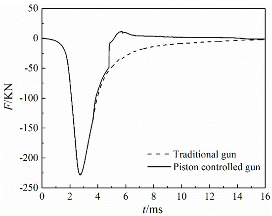
Figure 13.
Recoil comparison of two guns.
It can be seen from Figure 14 that the recoil momentum of the piston-controlled gun also dropped at 3.62 ms and reached the minimum value of 372.77 N·s at 14.17 ms. From then on, the recoil momentum of the piston-controlled gun began to increase. The reasons are as follows. As the rear spray channel was fully closed at 13.96 ms, the propellant gas in the exhaust pipe was completely ejected out, and then no reverse thrust would be produced. During the propulsion process, the recoil momentum of the traditional gun was 549.72 N·s, while that of the piston-controlled gun was 374.91 N·s, so the recoil reduction efficiency was 31.80%.
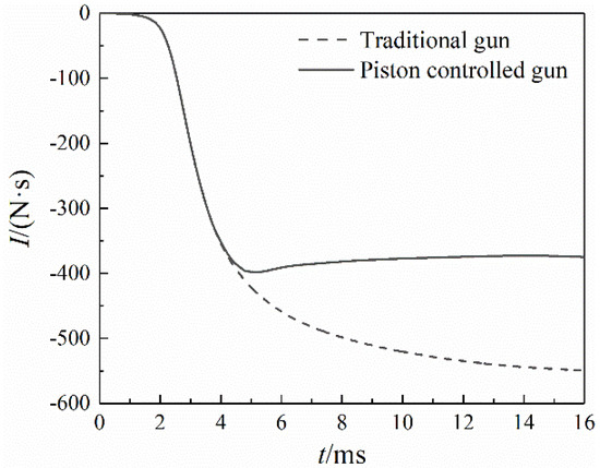
Figure 14.
Recoil momentum comparison of two guns.
There are many parameters which influence the recoil reduction efficiency, such as the size of the barrel vent, the length of the exhaust pipe, and the nozzle expanding angle. Thus, the piston-controlled gun needs to be optimized.
6. Conclusions
Numerical simulations in the piston-controlled gun were carried out based on one-dimensional two-phase theory. The flow field characteristics in the barrel, the piston cavity, and the exhaust pipe were obtained. The main conclusions are as follows.
- (1)
- The recoil reduction mechanism of the piston-controlled gun was revealed. By controlling the lateral ejecting of propellant gas with the piston, the rarefaction wave produced at the barrel vent just caught the projectile at the muzzle exit. Thus, the projectile base pressure did not reduce too much during the propulsion process, minimally reducing the muzzle velocity. Meanwhile, the recoil momentum was significantly reduced by venting high-pressure propellant gas from the barrel as much as possible.
- (2)
- The piston-controlled gun could be reset within the firing cycle, so the continuous firing mode is not affected. However, the rear spray channel will be closed during the piston reset motion, which is negative to the recoil reduction efficiency.
- (3)
- After the projectile reached the barrel vent, some high-pressure propellant gas flowed into the piston cavity, so the projectile base pressure dropped slightly. However, the piston cavity was closed before the rear spray channel was opened, so the velocity loss of the piston-controlled gun is similar to that of a traditional air-guided gun.
The recoil reduction method proposed in this work does not break the ammunition structure of the existing weapons. Besides, the reset device is stable, and the continuous firing mode is not affected. Thus, this method has a good application prospect.
Author Contributions
Conceptualization, M.Q.; methodology, M.Q. and P.S.; software, P.S.; validation, M.Q. and P.S.; formal analysis, M.Q. and P.S.; investigation, M.Q. and P.S.; resources, M.Q. and P.S.; data curation, M.Q. and P.S.; writing—original draft preparation, M.Q. and P.S.; writing—review and editing, M.Q., P.S., J.S. and Z.L.; visualization, P.S. and J.S.; supervision, M.Q. and Z.L.; project administration, M.Q. and Z.L.; funding acquisition, M.Q. All authors have read and agreed to the published version of the manuscript.
Funding
This research was funded by the National Natural Science Foundation of China, grant number 12072161 and 51376090.
Institutional Review Board Statement
Not applicable.
Informed Consent Statement
Not applicable.
Data Availability Statement
Not applicable.
Acknowledgments
This work was funded by the National Natural Science Foundation of China (Grant No. 12072161 and No. 51376090).
Conflicts of Interest
The authors declare that there is no conflict of interest.
References
- Kang, K.J.; Gimm, H.I. Numerical and experimental studies on the dynamic behaviors of a gun that uses the soft recoil system. J. Mech. Sci. Technol. 2012, 26, 2167–2170. [Google Scholar] [CrossRef]
- Qing, O.Y.; Zheng, J.J.; Li, Z.C. Controllability analysis and testing of a novel magnetorheological absorber for field gun recoil mitigation. Smart Mater. Struct. 2016, 25, 115041. [Google Scholar]
- Ahmadian, M.; Poynor, J.C. An evaluation of magneto rheological dampers for controlling gun recoil dynamics. Shock Vib. 2001, 8, 147–155. [Google Scholar] [CrossRef]
- Li, J.S.; Qiu, M.; Liao, Z.Q. Dynamic modeling and simulation of gatling gun with muzzle assistant-rotating and recoil absorber. Acta Armam. 2014, 35, 1344–1349. [Google Scholar]
- Cayzac, R.; Carettet, E.; Alziary de Roquefort, T. 3D unsteady intermediate ballistics modelling: Muzzle brake and sabot separation. In Proceedings of the 24th International Symposium on Ballistics, New Orleans, LA, USA, 22–26 September 2008. [Google Scholar]
- Kathe, E. Sonic Rarefaction Wave Recoilless Gun System. Patent 6460446B1-EN, 8 August 2002. [Google Scholar]
- Kathe, E.; Dillon, R. Sonic Rarefaction Wave Low Recoil Gun; US Army Armament Research, No. ARCCB-TR-02001; Watervilet: New York, NY, USA, 2002. [Google Scholar]
- Liao, Z.Q.; Qiu, M. Gas Dynamics of Automatic Weapons, 1st ed.; Defense Industry Press: Beijing, China, 2015; p. 247. [Google Scholar]
- Chen, Y.; Liao, Z.Q.; Liu, G.X.; Wang, T. Performance comparison of the two recoilless structure with Laval nozzles. J. Ball 2008, 20, 88–91. [Google Scholar]
- Cheng, C.; Wang, C.; Zhang, X.B. A prediction method for the performance of a low-recoil gun with front nozzle. Def. Technol. 2019, 15, 703–712. [Google Scholar] [CrossRef]
- Zhang, X.B.; Wang, Y.Z. Analysis of dynamic characteristics for rarefaction wave gun during the launching. J. Appl. Mech. 2010, 77, 051601. [Google Scholar] [CrossRef]
- Wang, Y.Z.; Zhang, X.B. Numerical analysis on launch property of rarefaction wave gun. Chin. J. High Pressure Phys. 2009, 23, 433–440. [Google Scholar]
- Zhang, F.; Liao, Z.Q.; Liu, G.X.; Chen, Y. Interior ballistics study on rarefaction wave gun based on theory of two-phase flow. J. Ball 2007, 19, 9–12. [Google Scholar]
- Zhang, F.; Liao, Z.Q.; Liu, G.X.; Chen, Y. Study of influence factors on launching performance of rarefaction wave gun. Acta Armam. 2008, 29, 23–27. [Google Scholar]
- Zhang, F.; Liao, Z.Q.; Liu, G.X.; Chen, Y. Numerical simulation and analysis on front orifice rarefaction wave gun propulsion. J. Syst. Simul. 2008, 20, 5032–5034. [Google Scholar]
- Coffee, T.P. Modeling of the 35-mm Rarefaction Wave Gun; Army Research Laboratory, No. ARL-TR-3792; Aberdeen Province Ground: Harford County, MD, USA, 2006. [Google Scholar]
- Xiao, J.; Yang, G.; Li, H.; Qiu, M.; Liao, Z. Dynamic modeling and simulation of recoil reduction of automatic weapon by time-delay nozzle. Acta Armam. 2017, 38, 1909–1917. [Google Scholar]
- Weng, C.S.; Wang, H. Computational Interior Ballistics, 1st ed.; Defense Industry Press: Beijing, China, 2006; p. 71. [Google Scholar]
- Nussbaum, J.; Helluy, P.; Hérard, J.-M.; Carriére, A. Numerical simulations of gas-particle flows with combustion. Flow Turbul. Combust. 2006, 76, 403–417. [Google Scholar] [CrossRef]
- Rashad, M.M.; Zhang, X.B.; Sadek, H.E.; Cheng, C. Two-phase flow interior ballistics model of laval large caliber guided projectile gun system. Appl. Mech. Mater. 2014, 465, 592–596. [Google Scholar]
- Jang, J.; Oh, S.; Roh, T. Development of three-dimensional numerical model for combustion-flow in interior ballistics. J. Mech. Sci. Technol. 2016, 30, 1631–1637. [Google Scholar] [CrossRef]
- Chirame, N.A.; Pradhan, D.; Naik, S.D. Operator splitting technique with FORCE scheme employed to simulate pressure wave motion inside gun chamber. Appl. Math. Model. 2015, 39, 2139–2154. [Google Scholar] [CrossRef]
- Otón-Martínez, R.A.; Monreal-González, G.; García-Cascales, J.R.; Vera-García, F.F.; Velasco, J.S.F.; Ramírez-Fernández, F.J. An approach formulated in terms of conserved variables for the characterisation of propellant combustion in internal ballistics. Int. J. Numer. Meth. FLUIDS 2015, 79, 394–415. [Google Scholar] [CrossRef]
- Monreal-González, G.; Otón-Martínez, R.A.; Velasco, F.J.S.; García-Cascáles, J.R.; Ramírez-Fernández, F.J. One-dimensional modelling of internal ballistics. J. Energ. Mater. 2017, 35, 397–420. [Google Scholar]
- Menshov, I.S.; Nemtsev, M.Y.; Semenov, I.V. Numerical modeling of wave processes accompanying combustion of in-homogeneously distributed composite propellant. Comp. Math. Math. Phys. 2019, 59, 1528–1541. [Google Scholar] [CrossRef]
- Hu, C.B.; Zhang, X.B. A Riemann problem based coupling method for predicting the combustion of propellant in a gun launching process. Propellants Explos. Pyrotech. 2019, 44, 751–758. [Google Scholar] [CrossRef]
- Cheng, C.; Zhang, X.B. Two-dimensional numerical investigation of gas-solid reactive flow with moving boundary. Combust. Sci. Technol. 2015, 187, 977–998. [Google Scholar] [CrossRef]
- Cheng, C.; Zhang, X.B. Numerical investigation of two-phase reactive flow with two moving boundaries in a two-stage combustion system. Appl. Therm. Eng. 2019, 156, 422–431. [Google Scholar] [CrossRef]
- Cao, R.D.; Zhang, X.B. Design optimization for a launching system with novel structure. Def. Technol. 2019, 15, 680–689. [Google Scholar] [CrossRef]
- Cao, R.D.; Zhang, X.B. A novel launching system applying a relay chamber technology and its optimization. Propellants Explos. Pyrotech. 2019, 44, 1199–1205. [Google Scholar] [CrossRef]
Publisher’s Note: MDPI stays neutral with regard to jurisdictional claims in published maps and institutional affiliations. |
© 2021 by the authors. Licensee MDPI, Basel, Switzerland. This article is an open access article distributed under the terms and conditions of the Creative Commons Attribution (CC BY) license (http://creativecommons.org/licenses/by/4.0/).