Abstract
A new mathematical model is developed for the analytical study of two cracks in the upper plane of dissimilar materials under various mechanical loadings, i.e., shear, normal, tearing and mixed stresses with different geometry conditions. This problem is developed into a new mathematical model of hypersingular integral equations (HSIEs) by using the modified complex potentials (MCPs) function and the continuity conditions of the resultant force and displacement with the crack opening displacement (COD) function as the unknown. The newly obtained mathematical model of HSIEs are solved numerically by utilizing the appropriate quadrature formulas. Numerical computations and graphical demonstrations are carried out to observe the profound effect of the elastic constants ratio, mode of stresses and geometry conditions on the dimensionless stress intensity factors (SIFs) at the crack tips.
1. Introduction
Study on the vigor of materials and engineering structures provides a broad sense which is related to a review of the carrying capacity of a body with and without consideration of initial cracks. In order to predict the stress state or stress intensity in the vicinity of the crack tip due to the mechanical loading or residual stresses, one needs to determine very important factors, i.e., stress intensity factors (SIFs). The SIF is a fundamental parameter in fracture mechanics, and it is an important factor for safety analysis of the materials, structural stability and design analysis. Complex potential function (CPF) method introduced by Muskhelishvili [1] is the simplest and most rigorous method to investigate the behavior of SIFs, measured at the tip of cracks to determine the stability behavior of bodies or materials containing cracks or flaws. Many researchers used CPF methods to investigate the crack problems in an infinite plane [2,3,4], finite plane [5,6] and half plane [7,8,9]. Gray et al. [2] and Nik Long et al. [3] established the relevant hypersingular integral equations (HSIEs) using CPF method in calculating the SIFs with Green’s function, and crack opening displacement (COD) function as the unknown, respectively. Liu et al. [4] analyzed SIFs for two unequal-length collinear cracks using weight functions method with COD function as the unknown. Lai and Schijve [5] analyzed a single hole-edge crack in a finite plane using CPF methods with the treatment of boundary condition with the minimum potential energy principle. Moreover, Zhang et al. [6] analyzed multiple cracks in a finite plane by numerically solved a system of singular integral equations with the Gauss–Chebyshev quadrature, and evaluating the SIFs. Legros et al. [7] performed the analysis of multiple circular inclusions in an elastic half plane based on complex singular integral equation with the unknown tractions at each circular boundary approximated by a truncated complex Fourier series. Liu and Guo [8] used the CPF method to calculate the SIFs for the interaction between a screw dislocation and an oblique edge crack in a half plane with the help of Cauchy integral formula. Elfakhakhre et al. [9] investigated the behavior of the SIFs at the crack tips in half plane elasticity using the modified complex potentials (MCPs) with the distribution dislocation as the unknown function. As per the authors’ knowledge, no mathematical model of the HSIEs has been made to date to develop and study the crack phenomenon in dissimilar materials under various mechanical loadings using CPF method.
Many different methods were applied by the researchers to investigate the crack problems in dissimilar materials. Chen [10] used the Fredholm integral equations to evaluate the dimensionless SIFs for multiple inclined cracks in dissimilar materials under shear stress. It was obtained that the mathematical model for the multiple cracks in dissimilar materials were reduced to the model in an infinite plane when . According to Chen and Hasebe [11], the values of dimensionless SIFs depend on the elastic constant ratio and crack geometric. They used the mixed boundary value problems to obtain a logarithmic singular kernel for a circular arc crack in the upper plane of dissimilar materials. Isida and Noguchi [12] analyzed the crack problems in dissimilar materials by using the continuous distributions of the body force method along the cracks but excluded the interface cracks and singularity problems for cracks terminating at the interface. Zhou et al. [13] found that the dimensionless SIFs for an arbitrary crack problems in dissimilar materials depends on the thickness of the strip, crack configuration and the existence of the crack near the punch foundation. They used a system of complex Cauchy type singular integral equations. Long and Xu [14] applied the combination of direct boundary integral method and displacement discontinuity method to solve the crack problems in dissimilar materials. The result showed that the proposed method was efficient especially for the scaled thin layers in the application of practical hydraulic fracturing simulations. Hamzah et al. [15,16] used the HSIEs to calculate the dimensionless SIFs for multiple cracks in the upper plane and both upper and lower planes of dissimilar materials subjected to shear stress. They expanded their study to analyze the behavior of dimensionless SIFs under various mechanical loadings, however it focused on a single crack in the upper plane of dissimilar materials [17].
The present mathematical model is a novel investigation of dimensionless SIFs at the crack tip of the two cracks in the upper plane of dissimilar materials under various mechanical loadings such as shear, normal, tearing and mixed stresses with different geometry conditions. By using CPF method, the problem is formulated into HSIEs. The noticeable impact of elastic constants ratio, mechanical loading and geometry conditions on SIFs for dissimilar materials has been depicted by means of numerical computations and graphical demonstrations. Moreover, a comparative analysis is carried out for dimensionless SIFs in dissimilar materials under various mechanical loadings to elucidate the unrevealed facts. The present findings may assist engineers in investigating the stability behavior of the perfectly bonded dissimilar structures or materials under various mechanical loadings.
2. Mathematical Model of the Problem
The CPF method plays an important role in solving the crack problems in plane elasticity [1]. In this method, the stress components , resultant force function and displacements are related to two complex potentials and as follows
where , G is shear modulus of elasticity, for plane stress, for plane strain and v is Poisson’s ratio. The derivative of Equation (2) with respect to z gives
where the traction denotes the normal and tangential components along the crack segment . Note that the traction depends on the position of point z and the direction of the segment .
According to Nik Long and Eshkuvatov [3], the complex potentials for a crack L in an infinite plane can be expressed by
where is COD function defined by
and denote the displacements at point t of the upper and lower crack faces, respectively. Note that COD function has the following properties
at the crack tip , where .
Consider a crack in upper plane of dissimilar materials under various mechanical loadings; see Figure 1.
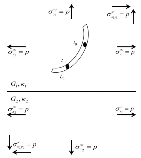
Figure 1.
A crack in dissimilar materials under various mechanical loadings.
The conditions for strain components in dissimilar materials are
where subscripts 1 and 2 are the strain components for the upper and lower planes of dissimilar materials, respectively. Those strains can be defined by Young’s modulus of elasticity E and stress components as
and
where and . For the shear stress, we have , , and applying condition Equation (10), Equation (11) is reduced to
For normal stress, we have , , and applying condition Equation (10), Equation (12) is reduced to
For tearing stress, we have and applying condition Equation (10), Equation (13) is reduced to
Whereas for mixed stress, we have and applying condition Equation (10), Equation (14) is reduced to
According to Chen and Hasebe [11], the MCPs for the crack in the upper plane of dissimilar materials are defined as
where and are the principal parts and and are the complementary parts of the complex potentials. The complex potentials for the lower plane are represented by and . Note that and are similar to the complex potentials for cracks in an infinite material. The continuity conditions for the resultant force (2) and displacement functions (3), yields
and
where , and + and − signs represent the upper and lower planes of dissimilar materials, respectively. Apply Equations (19) and (4) into Equations (20) and (21), the following expressions are obtainable
where . Note that is boundary of dissimilar materials, and are upper and lower planes of dissimilar materials, respectively, and , are elastic constants defined as
Consider two cracks and in the upper plane of dissimilar materials under various mechanical loadings; see Figure 2.
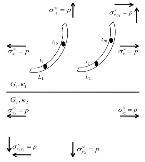
Figure 2.
Two cracks and in the upper plane of dissimilar materials.
In order to develop the new mathematical model of HSIEs for two cracks in the upper plane of dissimilar materials, we need to define four traction components , , and which consist of two groups of by using Equation (5). The first two tractions and are obtained when the observation point is placed at the point and , respectively, caused by at . Whereas, the second two tractions and are obtained when the observation point is placed at the point and , respectively, caused by at . Since both cracks lie in the upper part of dissimilar materials, we need to combine four traction components which consist of the principal and complementary parts . By using the superposition principle, the new mathematical model of HSIEs for two cracks in the upper plane of dissimilar materials can be obtained as follows
where
and . In Equation (26), the first three integrals on the right hand side represent the traction influence on crack caused by COD function on crack . The next three integrals represent the traction influence on crack caused by COD function on crack . Whereas in Equation (27), the first three integrals on the right hand side represent the traction influence on crack caused by COD function on crack . The next three integrals represent the traction influence on crack caused by COD function on crack . Note that the first integral with the equal sign in Equations (26) and (27) represents the hypersingular integral and must be defined as a finite part integral. If , then , Equations (26) and (27) reduce to the HSIEs for the two cracks in a half plane elasticity [18]. Whereas, if , then , Equations (26) and (27) reduce to the HSIEs for the two cracks in an infinite plane [3].
In order to solve the new mathematical model of HSIEs, the curved length coordinate method is used. Let
Then the following quadrature formulas can be applied [19,20,21,22]
and
where is a given function, ,
and
and the observation points
Here, is a Chebyshev polynomial of the second kind, defined by
The normal and tangential components of the HSIEs for the shear stress , normal stress , tearing stress and mixed stress with an angle of the crack are defined as follows
In order to investigate the behavior of dimensionless SIFs for two cracks in the upper plane of dissimilar materials under various mechanical loadings, we define the SIFs at the crack tips and as follows
where and are defined as follows
and . Therefore, the dimensionless SIFs at crack tips and are defined as follows
where
and are the Mode I dimensionless SIFs at crack tips and , respectively, and characterizes the amplitude of normal stress singularity. Whereas and are the Mode II dimensionless SIFs at crack tips and , respectively, and describe the amplitude of the shear stress singularity. Note that the crack propagates if the value of dimensionless SIFs is greater than or equal to the value of critical dimensionless SIFs [23]. The strength of the materials is getting weaker as the value of dimensionless SIFs increases [24]. Whereas the negative values of dimensionless SIFs were obtained for some geometric problems, implicatively insinuating the possible use of unknown contact and frictional stresses between the closed crack surfaces, thereby invalidating the presumption of a frictionless open crack model [25].
3. Numerical Results and Discussion
In this section, numerical computations and graphical demonstrations are carried out to show the effects of the elastic constants ratio, mode of stresses and geometry conditions on the dimensionless SIFs for crack problems in the upper plane of dissimilar materials. To validate the proposed mathematical model, we compared our numerical results with a crack parallel to the boundary of dissimilar materials investigated by Isida and Noguchi [12] in Table 1, and two cracks in the upper plane of dissimilar materials presented by Chen [10] in Table 2.

Table 1.
Stress intensity factors (SIFs) for a crack parallel to the boundary of dissimilar materials (Figure 3a).
Table 2.
SIFs for two cracks in the upper plane of dissimilar materials under various mechanical loadings (Figure 3b).
Consider the geometry conditions for crack problems in the upper plane of dissimilar materials under various mechanical loadings; see Figure 3.
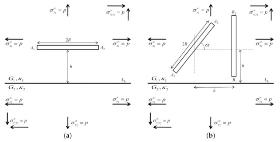
Figure 3.
The geometry conditions for crack problems in the upper plane of dissimilar materials. (a) A crack parallel to the boundary; (b) Two cracks in the upper plane.
Table 1 shows the dimensionless SIFs for a crack parallel to the boundary of dissimilar materials under normal stress when elastic constant ratio and varies (Figure 3a). Our numerical results totally agree with those of Isida and Noguchi [12]. We observed that at crack tip is equal to at crack tip . Whereas at crack tip is equal to the negative of at crack tip . This is due to the equivalence of the stress acting at the tips of the cracks.
Table 2 shows the dimensionless SIFs for two cracks in the upper plane of dissimilar materials under various mechanical loadings when and (Figure 3b). For shear stress, our numerical results agree with those of Chen [10]. For other stresses, the value of dimensionless SIFs are displayed in Figure 4, Figure 5, Figure 6, Figure 7. The dimensionless SIFs with black lines at crack tips and , and with blue lines at crack tips and under shear stress are delineated in Figure 4. It is found that as increases, decreases at all cracks tips. However increases when at tip and decreases at tip . As increases, increases at crack tips and . These numerical evidences show that the materials become weaker as increases and more stable as increases.
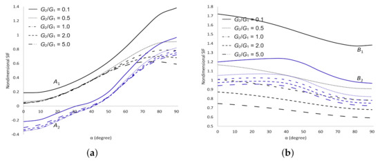
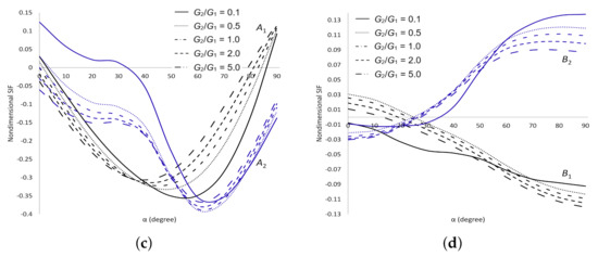
Figure 4.
SIFs for two cracks in the upper plane of dissimilar materials under shear stress. (a) Dimensionless SIF at crack tips and ; (b) Dimensionless SIF at crack tips and ; (c) Dimensionless SIF at crack tips and ; (d) Dimensionless SIF at crack tips and .
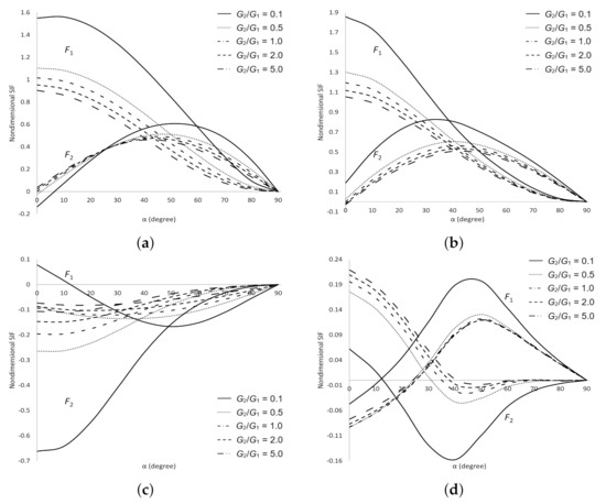
Figure 5.
SIFs for two cracks in the upper plane of dissimilar materials under normal stress. (a) Crack tip ; (b) Crack tip ; (c) Crack tip ; (d) Crack tip .
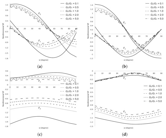
Figure 6.
SIFs for two cracks in the upper plane of dissimilar materials under tearing stress. (a) Crack tip ; (b) Crack tip ; (c) Crack tip ; (d) Crack tip .
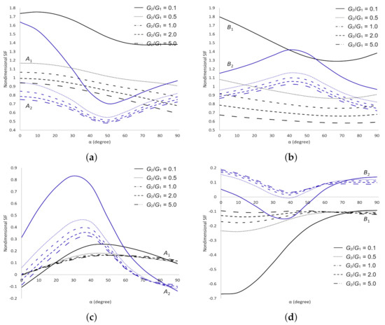
Figure 7.
SIFs for two cracks in the upper plane of dissimilar materials under mixed stress. (a) Dimensionless SIF at crack tips and ; (b) Dimensionless SIF at crack tips and ; (c) Dimensionless SIF at crack tips and ; (d) Dimensionless SIF at crack tips and .
The dimensionless SIFs under normal stress are delineated in Figure 5. It is observed that as increases decreases at cracks tips , and , and increases at tip . As increases decreases at crack tips and . Whereas as , the values of and are equal to zero at all cracks tips, due to the stress acting parallel to the geometric of the cracks. These observations show that the materials are more stable as and increase. The dimensionless SIFs under tearing stress are delineated in Figure 6. It demonstrates that as increases, increases at cracks tips , and but only increases at tips and . As increases, decreases at crack tips and . These results indicate that the strength of the materials depends on and . The dimensionless SIFs with black lines at crack tips and , and with blue lines at crack tips and under mixed stress are delineated in Figure 7. It portrays that as increases decreases at all cracks tips. As increases, decreases at crack tips and . These results enable us to conclude that the materials are more stable as increases.
Consider the geometry conditions for two cracks in the upper plane of dissimilar materials under various mechanical loadings as depicted in Figure 8.
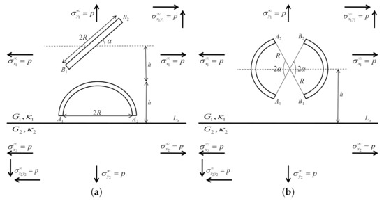
Figure 8.
The geometry conditions for two cracks in the upper plane of dissimilar materials. (a) A semi circular arc crack and an inclined crack; (b) Two equal circular arc cracks on the same circle.
The dimensionless SIFs with black lines at crack tips and , and with blue lines at crack tips and for a semi circular arc crack and an inclined crack in the upper plane of dissimilar materials under various mechanical loadings when and varies are plotted in Figure 9, Figure 10, Figure 11 and Figure 12 (Figure 8a).
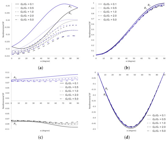
Figure 9.
SIFs for two cracks in the upper plane of dissimilar materials under shear stress. (a) Dimensionless SIF at crack tips and ; (b) Dimensionless SIF at crack tips and ; (c) Dimensionless SIF at crack tips and ; (d) Dimensionless SIF at crack tips and .
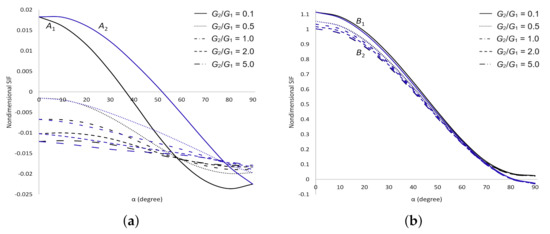
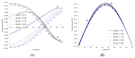
Figure 10.
SIFs for two cracks in the upper plane of dissimilar materials under normal stress. (a) Dimensionless SIF at crack tips and ; (b) Dimensionless SIF at crack tips and ; (c) Dimensionless SIF at crack tips and ; (d) Dimensionless SIF at crack tips and .
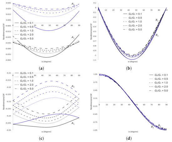
Figure 11.
SIFs for two cracks in the upper plane of dissimilar materials under tearing stress. (a) Dimensionless SIF at crack tips and ; (b) Dimensionless SIF at crack tips and ; (c) Dimensionless SIF at crack tips and ; (d) Dimensionless SIF at crack tips and .
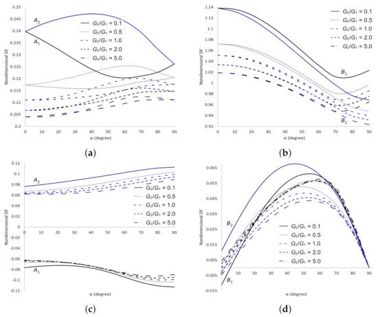
Figure 12.
SIFs for two cracks in the upper plane of dissimilar materials under mixed stress. (a) Dimensionless SIF at crack tips and ; (b) Dimensionless SIF at crack tips and ; (c) Dimensionless SIF at crack tips and ; (d) Dimensionless SIF at crack tips and .
The dimensionless SIFs under shear stress are delineated in Figure 9. It is found that as and increase decreases and increases, respectively at all cracks tips. As increases, increases at crack tip , decreases at tip and does not show any significant difference at tips and . These numerical evidences show that the materials are more stable as increases and are getting weaker as increases. The dimensionless SIFs under normal stress are delineated in Figure 10. It can be seen that as increases decreases at cracks tips and but at tips when and when . As increases, decreases at all cracks tips. These observations show that the materials are more stable as and increase. The dimensionless SIFs under tearing stress are delineated in Figure 11. It portrays that as increases increases at all cracks tips. As increases, decreases when at all cracks tips. These results show that the strength of the materials depends on the values of and . For mixed stress, the dimensionless SIFs are displayed in Figure 12. It is observed that as increases decreases at all cracks tips and decreases at crack tips and . As increases, does not show any significant difference at all cracks tips. These results enable us to conclude that the materials are more stable as increases.
Figure 13 shows a comparison of the dimensionless SIFs for two equal circular arc cracks on the same circle in the upper plane of dissimilar materials under shear stress when , and varies (Figure 8b). Our numerical results agree with those of Chen and Hasebe [26]. We observed that the value of is equal at all crack tips. Whereas at crack tips and are equal to the negative of at crack tips and , respectively. This is due to the equivalence of the stress acting at the tips of the cracks.
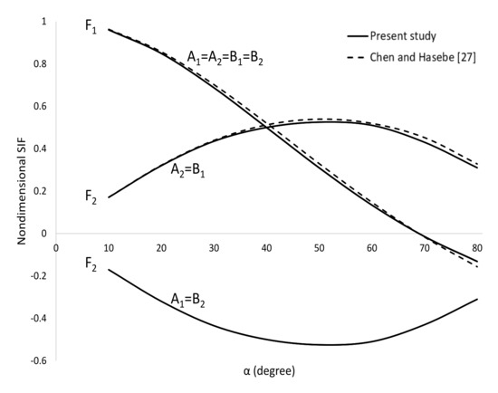
Figure 13.
Comparison of dimensionless SIFs between present study and Chen and Hasebe [26] at all crack tips.
For other values of dimensionless SIFs under various mechanical loadings are presented in Figure 14, Figure 15, Figure 16 and Figure 17. The dimensionless SIFs under shear stress are delineated in Figure 14. It is observed that at crack tips and are equal to at tips and , respectively. Whereas at crack tips and are equal to the negative of at tips and , respectively. As and increase, decreases at all cracks tips. As increases, increases at crack tips and , and decreases at tips and . These observations show that the materials are more stable as and increase.
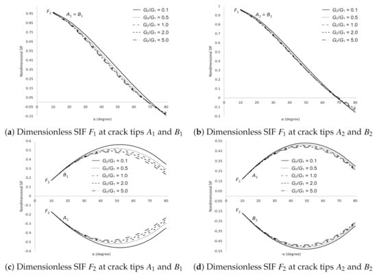
Figure 14.
SIFs for two cracks in the upper plane of dissimilar materials under shear stress. (a) Dimensionless SIF at crack tips and ; (b) Dimensionless SIF at crack tips and ; (c) Dimensionless SIF at crack tips and ; (d) Dimensionless SIF at crack tips and .
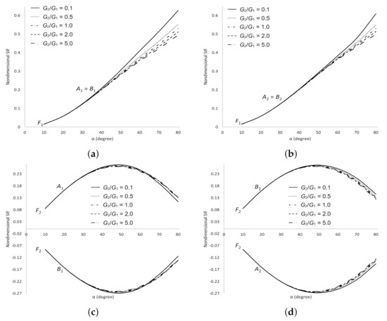
Figure 15.
SIFs for two cracks in the upper plane of dissimilar materials under normal stress. (a) Dimensionless SIF at crack tips and ; (b) Dimensionless SIF at crack tips and ; (c) Dimensionless SIF at crack tips and ; (d) Dimensionless SIF at crack tips and .
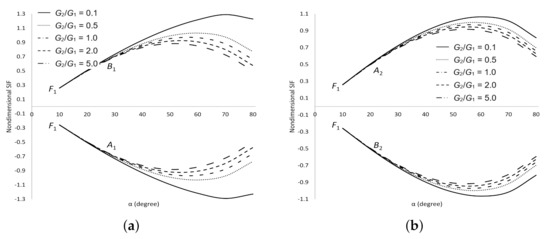
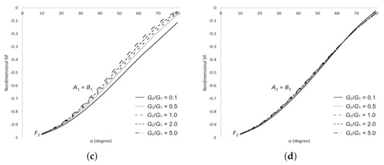
Figure 16.
SIFs for two cracks in the upper plane of dissimilar materials under tearing stress. (a) Dimensionless SIF at crack tips and ; (b) Dimensionless SIF at crack tips and ; (c) Dimensionless SIF at crack tips and ; (d) Dimensionless SIF at crack tips and .
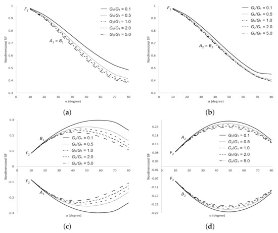
Figure 17.
SIFs for cracks in the upper plane of dissimilar materials under mixed stress. (a) Dimensionless SIF at crack tips and ; (b) Dimensionless SIF at crack tips and ; (c) Dimensionless SIF at crack tips and ; (d) Dimensionless SIF at crack tips and .
The dimensionless SIFs under normal stress are delineated in Figure 15. It demonstrates that at crack tips and are equal to at tips and , respectively. Whereas at crack tips and are equal to the negative of at tips and , respectively. As and increase, decreases and increases, respectively at all cracks tips. As increases, increases at crack tips and when , and decreases at tips and when . These results show that the materials are more stable as increases and become weaker as increases. The dimensionless SIFs under tearing stress are delineated in Figure 16. It is found that at crack tips and are equal to at tips and , respectively. Whereas at crack tips and are equal to the negative of at tips and , respectively. As increases, increases at crack tips and , and decreases at tips and . As increases, decreases at crack tips and when , and increases at tips and when . Whereas increases at all cracks tips as increases. These numerical evidences show that the materials are more stable as increases and become weaker as increases. The dimensionless SIFs under mixed stress are delineated in Figure 17. It is obtained that at crack tips and are equal to at tips and , respectively. Whereas at crack tips and are equal to the negative of at tips and , respectively. As and increase, decreases at all cracks tips. increases at crack tips and , and decreases at tips and as increases. These numerical results show that the materials are more stable as and increase.
4. Conclusions
The present mathematical model is focused on the analytical investigation of dimensionless SIFs at the crack tip of two cracks problems in the upper plane of dissimilar materials under various mechanical loadings such as shear, normal, tearing and mixed stresses with different geometry conditions. The problem was formulated into a new mathematical model of HSIEs by using the MCPs function and the continuity conditions of the resultant force and displacement with the crack opening displacement (COD) function as the unknown. The substantial effect of the elastic constant ratio , mode of stresses and geometry conditions of the cracks on dimensionless SIFs have been delineated by means of numerical computation and graphical demonstration. Moreover, the major outcomes of the present analysis can be attributed as follows:
- For and , the elementary solution of HSIEs is reduced to two cracks in half plane and infinite plane problems, respectively.
- The equivalence of the stress acting at the crack tip due to the geometric of the cracks resulted in equal values of dimensionless SIFs.
- The value of , types of stresses and geometry conditions of the crack affect the strength of the materials for two cracks in the upper part of dissimilar materials.
For future developments, the approach used in this paper could be extended to investigate the behavior of dimensionless SIFs for others geometry conditions in dissimilar materials under various mechanical loadings. It also can be extended to the three-dimensional cracks problems in dissimilar materials with guided work from Chen and Lee [27].
Author Contributions
Conceptualization, K.B.H., N.M.A.N.L., N.S. and Z.K.E.; methodology, K.B.H. and N.M.A.N.L.; software, K.B.H. and N.M.A.N.L.; validation, K.B.H. and N.M.A.N.L.; formal analysis, K.B.H. and N.M.A.N.L.; writing—original draft preparation, K.B.H.; writing—review and editing, N.M.A.N.L.; supervision, N.M.A.N.L., N.S. and Z.K.E. All authors have read and agreed to the published version of the manuscript.
Funding
Ministry of Higher Education Malaysia through Fundamental Research Grant Scheme (Project no: 5540269).
Institutional Review Board Statement
Not applicable.
Informed Consent Statement
Not applicable.
Data Availability Statement
Data is contained within the article.
Acknowledgments
The authors would like to thanks the Universiti Teknikal Malaysia Melaka (UTeM), Universiti Putra Malaysia (UPM) and Ministry of Higher Education Malaysia. The second author would like to thanks the Ministry of Higher Education Malaysia for the financial support through Fundamental Research Grant Scheme (Project no: 5540269).
Conflicts of Interest
The authors declare no conflict of interest.
Abbreviations
The following abbreviations are used in this manuscript:
| COD | Crack Opening Displacement |
| CPF | Complex Potentials Function |
| HSIEs | Hypersingular Integral Equations |
| MCPs | Modified Complex Potentials |
| SIFs | Stress Intensity Factors |
Glossary of Symbols
The following symbols are used in this manuscript:
| , , | Complex Potentials Functions |
| , , | Upper plane of Complex Potentials Functions |
| , , | Principal part of Complex Potentials Functions |
| , , | Complementary part of Complex Potentials Functions |
| , , | Lower plane of Complex Potentials Functions |
| , , | Stress components |
| Strain component | |
| G | Shear modulus |
| v | Poisson’s ration |
| Crack Opening Displacement function | |
| Elastic constant | |
| Stress Intensity Factors at crack tip | |
| Dimensionless Stress Intensity Factors at crack tip | |
| Hypersingular integral and must be defined as a finite part integral | |
| ≃ | Similarity equation |
| The traction influence on crack i caused by COD function on crack j |
References
- Muskhelishvili, N.I. Some Basic Problems of the Mathematical Theory of Elasticity; Noordhoff International Publishing: Leyden, IL, USA, 1953. [Google Scholar]
- Gray, L.J.; Martha, L.F.; Ingraffea, A.R. Hypersingular integrals in boundary element fracture analysis. Int. J. Numer. Methods Eng. 1990, 29, 1135–1158. [Google Scholar] [CrossRef]
- Nik Long, N.M.A.; Eshkuvatov, Z.K. Hypersingular integral equation for multiple curved cracks problem in plane elasticity. Int. J. Solids Struct. 2009, 46, 2611–2617. [Google Scholar] [CrossRef]
- Liu, Z.X.; Xu, W.; Yu, Y.; Wu, X.R. Weight Functions and Stress Intensity Factors for Two Unequal-Length Collinear Cracks in an Infinite Sheet. Eng. Fract. Mech. 2019, 209, 173–186. [Google Scholar] [CrossRef]
- Lai, J.; Schijve, J. The stress intensity factor and stress concentration for a finite plate with a single crack emanating from a hole. Eng. Fract. Mech. 1990, 36, 619–630. [Google Scholar] [CrossRef][Green Version]
- Zhang, J.; Qu, Z.; Liu, W.; Wang, L. Automated numerical simulation of the propagation of multiple cracks in a finite plane using the distributed dislocation method. Comptes Rendus Mec. 2019, 347, 191–206. [Google Scholar] [CrossRef]
- Legros, B.; Mogilevskaya, S.G.; Crouch, S.L. A boundary integral method for multiple circular inclusions in an elastic half-plane. Eng. Anal. Bound. Elem. 2004, 28, 1083–1098. [Google Scholar] [CrossRef]
- Liu, X.; Guo, J. Interaction between a screw dislocation and oblique edge crack in a half-infinite MEE solid. Theor. Appl. Fract. Mech. 2016, 86, 225–232. [Google Scholar] [CrossRef]
- Elfakhakhre, N.R.F.; Nik Long, N.M.A.; Eshkuvatov, Z.K. Numerical solutions for cracks in an elastic half-plane. Acta Mech. Sin. 2019, 35, 212–227. [Google Scholar] [CrossRef]
- Chen, Y.Z. Multiple crack problems for two bonded half planes in plane and antiplane elasticity. Eng. Fract. Mech. 1986, 25, 1–9. [Google Scholar] [CrossRef]
- Chen, Y.Z.; Hasebe, N. Stress-intensity factors for curved circular crack in bonded dissimilar materials. Theor. Appl. Fract. Mech. 1992, 17, 189–196. [Google Scholar] [CrossRef]
- Isida, M.; Noguchi, H. Arbitrary array of cracks in bonded half planes subjected to various loadings. Eng. Fract. Mech. 1993, 46, 365–380. [Google Scholar] [CrossRef]
- Zhou, Y.T.; Li, X.; Yu, D.H. Integral method for contact problem of bonded plane material with arbitrary cracks. Comput. Model. Eng. Sci 2008, 36, 147–172. [Google Scholar]
- Long, G.; Xu, G. A combined boundary integral method for analysis of crack problems in multilayered elastic media. Int. J. Appl. Mech. 2016, 8, 1650070. [Google Scholar] [CrossRef]
- Hamzah, K.B.; Nik Long, N.M.A.; Senu, N.; Eshkuvatov, Z.K. Stress intensity factor for multiple cracks in bonded dissimilar materials using hypersingular integral equations. Appl. Math. Model. 2019, 73, 95–108. [Google Scholar] [CrossRef]
- Hamzah, K.B.; Nik Long, N.M.A.; Senu, N.; Eshkuvatov, Z.K. Stress intensity factor for bonded dissimilar materials weakened by multiple cracks. Appl. Math. Model. 2020, 77, 585–601. [Google Scholar] [CrossRef]
- Hamzah, K.B.; Nik Long, N.M.A.; Senu, N.; Eshkuvatov, Z.K.; Ilias, M.R. Stress intensity factors for a crack in bonded dissimilar materials subjected to various stresses. Univers. J. Mech. Eng. 2019, 7, 179–189. [Google Scholar] [CrossRef]
- Chen, Y.Z.; Lin, X.Y.; Wang, X.Z. Numerical solution for curved crack problem in elastic half-plane using hypersingular integral equation. Philos. Mag. 2009, 89, 2239–2253. [Google Scholar] [CrossRef]
- Monegato, G. Numerical evaluation of hypersingular integrals. J. Comput. Appl. Math. 1994, 50, 9–31. [Google Scholar] [CrossRef]
- Mayrhofer, K.; Fischer, F.D. Derivation of a new analytical solution for a general two-dimensional finite-part integral applicable in fracture mechanics. Int. J. Numer. Method Eng. 1992, 33, 1027–1047. [Google Scholar] [CrossRef]
- Mason, T.C.; Handscomb, D.C. Chebyshev Polynomials; Chapman and Hall/CRC: Boca Raton, FL, USA, 2003. [Google Scholar]
- Kythe, P.K.; Schaferkotter, M.R. Handbook of Computational Methods for Integration; Chapman and Hall/CRC: Boca Raton, FL, USA, 2004. [Google Scholar]
- Petersen, R.C. Accurate critical stress intensity factor Griffith crack theory measurements by numerical techniques. SAMPE J. Soc. Adv. Mater. Process. Eng. 2013, 2013, 737–752. [Google Scholar]
- Wang, T.C. Fundamentals of interface mechanics. Ref. Modul. Mater. Sci. Mater. Eng. 2003, 8, 89–135. [Google Scholar]
- Choi, H.J. Thermoelastic interaction of two offset interfacial cracks in bonded dissimilar half-planes with a functionally graded interlayer. Acta Mech. 2014, 225, 2111–2131. [Google Scholar] [CrossRef]
- Chen, Y.Z.; Hasebe, N. Fredholm integral equation for the multiple circular arc crack problem in plane elasticity. Arch. Appl. Mech. 1997, 67, 433–446. [Google Scholar] [CrossRef]
- Chen, Y.Z.; Lee, K.Y. Numerical solution of three-dimensional crack problem by using hypersingular integral equation. Comput. Methods Appl. Mech. Eng. 2001, 190, 4019–4026. [Google Scholar] [CrossRef]
Publisher’s Note: MDPI stays neutral with regard to jurisdictional claims in published maps and institutional affiliations. |
© 2021 by the authors. Licensee MDPI, Basel, Switzerland. This article is an open access article distributed under the terms and conditions of the Creative Commons Attribution (CC BY) license (http://creativecommons.org/licenses/by/4.0/).