Abstract
Hand-eye calibration and three-dimensional space target positioning are the keys to realize the automatic grasping of the manipulator. Aiming at the problems of a difficult camera manipulator calibration and poor real-time segmentation and positioning of stacked targets in industrial environment, a rapid target positioning method of self-calibration manipulator is proposed. Firstly, the spatial spherical autonomous path planning is carried out based on the quaternion linear interpolation method to calculate spatially symmetric path trajectory of the calibrator. The RGB-D camera mounted at the end of the manipulator is used to obtain multiple groups of RGB and depth images of the calibration plate. Combined with the position and attitude of the manipulator end, the internal and external parameters of the camera and the hand-eye conversion matrix are automatically calibrated. Then, based on KD tree algorithm, the holes in the point cloud are extracted to plan the shooting pose of the complementary image, and the target object is photographed from multiple symmetric angles. Combined with the iterative shooting pose of the manipulator, the rapid registration of the point cloud is realized and the complete outer surface model of the target object is obtained. Finally, the improved double pyramid feature fusion depth image is used to segment the RGB image through Mask R-CNN and mapped to the point cloud space, to achieve fast target segmentation of end-to-end 3D point cloud. The experimental results show that the eye-in-hand manipulator system can be self-calibrated to greatly simplify the calibration process and achieve the calibration accuracy of the traditional calibration method. The average error in each direction of the calibration result is less than 2 mm, which can achieve the acquisition accuracy of the vision sensor. It can also register and reconstruct point clouds for complex scenes in 1 s. The improved Mask-RCNN increases the segmentation accuracy of stacking objects by 8%. Compared with the physical error of hardware, the positioning error is no more than 0.89% and can meet the requirements of practical applications.
1. Introduction
In industrial scenes, robots to perceive the 3D environment and operate on targets are the key to achieving intelligent manufacturing [1,2]. The realization of rapid self-calibration and rapid spatial positioning of targets in complex environments is important technologies, and they have always been hotspots in robotics and computer vision [3,4].
In order to recognize, locate and manipulate objects in 3D environment, robots must locate their poses and then operate them accordingly through robot actuators. The establishment of a vision-based intelligent robot system usually requires calibration of the spatial posture relationship between vision sensor and robot actuator (hand-eye calibration). The point cloud model is widely used in industrial 3D vision for its flexibility, matrix representation and ease of calculation. The robot perceives the environment and targets through 3D vision and needs to reconstruct the spatial environment through point clouds. The target object is segmented from the environment to achieve specific operations on the object, such as machine assembly, industrial stacked parts sorting and 3D reconstruction of large components.
The calibration of the vision system is divided into camera calibration and hand-eye calibration. Due to the physical properties of the lens in the vision sensor, the image will be distorted. Camera calibration calculates the aberration coefficients and the physical parameters of lens, and then establishes the conversion relationships of image pixel coordinates to physical coordinate systems. Zhang proposed a classical camera calibration method by using a checkerboard as a calibration plate to calibrate cameras. This method is widely used in camera calibration for its high calibration accuracy [5].
In terms of point cloud reconstruction after calibration, point cloud registration have to be carried out. Traditional hand-eye calibration methods generally require professional operators to operate cameras and manipulators to shoot multiple calibration images. For example, Arne Peters et al. proposed a calibration method for a six-axis robot based on 2D laser rangefinder, and the robot can be calibrated by hand-eye without standard calibration parts [6]. Mingyang Li et al. carried out hand-eye calibration of the robot from the perspective of 3D reconstruction and proposed a reconstruction-based calibration accuracy evaluation method [7]. Although these methods can calibrate the internal and external parameters of the camera and the relationship between the end- effector of the manipulator and the camera, the process is generally too complicated. Operators are required to have a professional level, especially in environments that operators cannot reach. The rapid, automatic and accurate calibration of the robot hand-eye system cannot be achieved, and the application occasions and production efficiency of the robot are limited.
Spatial point cloud registration matches the points with the same meaning obtained from the point cloud in the same scene, aligning the two clouds in the same coordinate system through spatial transformation so as to reconstruct the expression of the three-dimensional model of the target in the manipulator coordinate system. This is a prerequisite for spatial positioning [7,8]. Boce Xue et al. realized the three-dimensional reconstruction of the welding joint based on Kalman filter and more, and guided the robot to complete the welding of the joint [9]. Peters Arne et al. used a two-dimensional LiDAR to generate a 3D scan of the surrounding area through a moving sensor, and ran an iterative closest point (ICP) variant on it to estimate the missing part of the motion chain to reconstruct a three-dimensional model of the environment [6]. These registration algorithms based on point pair relationship generally have the disadvantages of time-consuming, insufficient accuracy and noise sensitivity, which seriously affect the real-time and accuracy of the manipulator operation. QY Zhou presented an algorithm for fast global registration of partially overlapping 3D surfaces. The algorithm operates on candidate matches that covers the surfaces [10]. However, it requires a complete point cloud to register the target point cloud, so it is not suitable for point cloud registration of unknown objects. Yang, H et al. proposed the first fast and certifiable algorithm for the registration of two sets of point cloud in the presence of large amounts of outlier correspondence. Additionally, it is more accurate than ICP while being orders of magnitude faster, and with the continuous improvement of 3D datasets in recent years, deep learning has started to be applied in 3D feature matching algorithms [10,11]. Zeng et al. proposed a deep learning model based on 3DMatch for local feature learning [12], which is a data-driven model that learns a local volumetric patch descriptor for establishing correspondence between partial 3D data. Using 3DMatch for self-supervised feature learning to obtain local feature descriptors.
In the registered point cloud space, segmenting the object of interest from the background and other objects for spatial positioning is a key step for the manipulator to achieve target positioning. Zhao et al. proposed an improved pattern matching segmentation algorithm based on the maximum likelihood estimation sampling consensus (MLESAC) algorithm to refine and segment indoor objects [13]. Awwad proposed an improved plane segmentation method based on Seq-NV-RANSAC for unstructured 3D point clouds [14]. These methods can segment space objects. However, because they all directly operate on massive point cloud data, and they require extensive computational resources. Moreover, due to the interference of random noise, these methods have poor segmentation effects on randomly stacked objects. Recently, deep learning theory and practice have been continuously applied in many topics. Maturana et al. proposed a Voxnet structure, which uses 3D CNN to process the voxels of the grid, rasterize the 3D shape and sample the distance function on dense voxels, and apply 3D CNN on the whole voxels to classify 3D data quickly and accurately [15]. However, this algorithm uses the voxel space as the definition domain of calculation. It needs large computation, is uneasy to store, and depends on the accuracy of voxel segmentation.
In this paper, algorithms are designed based on three necessary stages (Hand-eye calibration, point cloud reconstruction, point cloud segmentation) of an intelligent robot system with 3D vision. A RGB camera and a depth camera are used to form the RGB-D camera, which are mounted near the end-effector. Aiming at the problem of cumbersome hand-eye calibration steps and relying on manual operation to a large extent, a self-calibration method of eye-in-hand manipulator system is proposed. It automatically plans image acquisition path planning based on quaternion spherical linear interpolation method to calculate spatially symmetric path trajectory of the calibrator, and collects multiple sets of photos of the calibration board. Combining the RGB camera, the depth camera and in the end pose of the manipulator, the internal parameter matrix, external parameter matrix and hand-eye conversion matrix of the RGB-D camera (RGB camera and depth camera) can be solved without human intervention. With regard to the poor real-time and low accuracy of traditional point cloud registration, a rapid point cloud registration method based on the shooting pose space coordinate conversion of iterative manipulator is proposed. The missing part of the point cloud is extracted and the symmetric shooting pose of the complementary image is planned, to fill the point cloud holes caused by the shooting blind area and improve the registration accuracy. Complete point cloud reconstruction of the environment and stationary objects. Due to the poor real-time performance of traditional point cloud target segmentation method and poor adaptability to stacked targets, an improved double pyramid feature fusion depth image is proposed to segment the RGB image through Mask R-CNN [16] and map it to the point cloud space to realize the rapid instance segmentation of point cloud targets.
The main contributions of this paper are as follows: (1) a self-calibration method of eye-in-hand manipulator system is proposed; (2) a millisecond fast and accurate point cloud hole completion registration method is proposed, which can quickly reconstruct the outer surface model of the static target object; (3) a 2D to 3D end-to-end 3D segmentation method is proposed, and finally an independent point cloud of stacked objects is obtained to achieve fast and accurate point cloud segmentation.
2. Related Works
The operation of the robot on the target object involves hand-eye calibration [6], point cloud reconstruction [17] and segmentation [13] technology, and these technologies have also been research hotspots.
- (1)
- Vision system calibration
The calibration of the vision system is divided into camera internal parameter calibration and hand-eye calibration. For RGB-D camera, if use it to generate point cloud image with texture information, it is necessary to calibrate RGB camera and depth camera to obtain the relationship between RGB image and depth image.
Currently, the calibration method of camera internal parameters mainly uses Zhang Zhengyou calibration method [5]. However, in view of the problem that the depth camera cannot find the corner points of the checkerboard, SMISEK J et al. [18] proposed to block the infrared transmitter of the RGB-D camera and use a halogen lamp to generate infrared images, and infrared images instead of depth images are used to calibrate the position between the two cameras. Zhang et al. [19] proposed the maximum likelihood solution for the joint calibration of two cameras, according to the criterion that the points on the depth image calibration plate should be coplanar and the corresponding points of depth image and color image can be specially specified.
The hand-eye calibration of RGB-D camera is the same as that of RGB camera. Tsai et al. [20] proposed a new analytical algorithm for hand-eye calibration and gave the principle of selecting the data set for hand-eye calibration under this method for the first time. Fassi I et al. [21] proposed an algorithm to analyze the hand-eye calibration matrix formula from a geometric perspective, and studied the excessive restriction and singularity in the algorithm.
However, the above methods all need to be carried out independently. The operation of camera calibration needs to be completed first to obtain the calibration result, and then the operation of hand-eye calibration is carried. Moreover, most of the calibration of RGB-D cameras requires additional hardware equipment overhead. Whether it is camera internal parameter and distortion coefficient calibration or hand-eye calibration, it is necessary to move the camera and calibration parts multiple times to collect multi-calibration parts pictures to obtain landmark points to solve the overdetermined linear equations and obtain the results. The process requires professional manual intervention, which brings trouble to actual operation. Combined with the advantages of controllable pose of the manipulator, this paper uses the calibration parts that can be recognized by both RGB camera and depth camera to complete the internal and external parameter calibration of the camera and hand-eye calibration and reduce manual intervention as much as possible.
- (2)
- Point cloud registration
In terms of point cloud reconstruction after calibration, it is necessary to take a global shot of the object during the reconstruction process to obtain complete three-dimensional information, as the point cloud data collected from different viewpoints are based on the coordinate system of the vision sensor. The point clouds are all unified in the same world coordinate system to complete the point cloud completion and reconstruction, which requires the point cloud registration [22]. Coarse registration provides a good initial value for fine registration, minimizing the spatial position difference between point clouds to achieve three-dimensional reconstruction. Currently, the more common point cloud coarse registration algorithms are PFH (point feature histogram) [23], FPFH (fast point feature histogram) [24], 3Dsc (3D shape context) [25]. The more common point cloud precision registration algorithms are NDT (normal distribution transformation) [26], ICP (iterative closest point) [27] and their variants [28,29].
In addition to the classic algorithm mentioned above, Thirion J et al. [30] proposed to establish an extremal mesh based on the special principal curvature in the point cloud model, and to use its rigid body transformation invariance to carry out coarse registration. However, the mesh established by this method is often vulnerable to noise interference and is only suitable for ideal models. Aiger et al. [31] believe that when the noise of the point cloud is in a certain threshold, the coarse registration can be achieved only based on the congruence relationship of the quadrilateral formed by four coplanar points. Nevertheless, it adopts the idea of exhaustive, which computationally expensive. Mellado et al. [32] proposed a coarse registration method based on index technology to realize the linear time complexity in view of the low global comparison efficiency of [31] proposed algorithm. Fast Global Registration [10] is widely used for its fast performance. However, in order to increase the registration accuracy and speed, lots of parameters need to be set. Sukhyun Lim et al. proposed a method to help Fast Global Registration set parameters [33]. Through analysis and experiment, the parameters that work effectively in actual registration are proposed. This result will help determine the direction when a Fast Global Registration method is needed. Li et al. proposed a point cloud registration method based on convolutional neural networks with improved Harris-SIFT (scale-invariant feature transform) [34]. They improved Harris-SIFT to extract the stable key points of point cloud models in 3D space. Meanwhile, the weighted adjacency matrix of the key points is used as the input feature map of the convolutional neural network to achieve the prediction matching of key points of the source and target point clouds. However, in order to extract key points accurately, this algorithm must target point clouds with a large number of repetitive parts.
However, the above rough registration algorithm of point cloud usually has the characteristics of large calculation and time-consuming, which cannot ensure the accurate registration of two point clouds under noise or strong convergence. In this paper, combined with the controllable nature of the hand-eye system, the missing point cloud is automatically detected, and the missing parts are registered in a targeted manner to repair the missing point cloud and improve the real-time registration.
- (3)
- Point cloud instance segmentation
After obtaining a more complete environmental point cloud model, only when the target object is extracted from the environment can the manipulator carry out corresponding operations on the target [29]. Traditional point cloud segmentation mainly uses the position relationship between points in point cloud data to segment it, mainly including clustering and region growth. Wang et al. proposed a point cloud segmentation algorithm that uses the core ideas of local sampling and statistical inference. The algorithm uses anomalous sample datasets to determine the planes and surfaces in the point cloud data to obtain valid samples, using local evaluation and constraints to obtain segmentation results [35]. However, the traditional point cloud segmentation methods cannot meet the requirements of real-time semantic segmentation of large-scale point cloud in artificial intelligence, and cannot accurately segment continuous contact objects, such as stacking in most cases.
Kalogerakis et al. [36] designed a projection convolutional network applied to 3D shape segmentation, and proposed a deep network architecture for 3D shape segmentation and inferred recognition of individual parts. The algorithm combines FCNs (fully convolutional networks) and CRFs (conditional random field) by using a pre-trained model for image recognition of end-to-end training. FCN projects multi-view images to different parts of the corresponding 3D objects, and then uses surface feature-based CRF to segment the 3D shapes by combining the features on the surfaces of different parts of the projected 3D objects. This method processes the input data efficiently with an image-based CNN, but cannot determine the size of the number of views covering the 3D model, which may lead to the loss of 3D information.
The development of two-dimensional image processing by RGB-D cameras and artificial intelligence provides a way to segment three-dimensional point clouds based on two-dimensional images for point cloud segmentation. The multi-view convolutional neural network (MVCNN) proposed by Su et al. [37] firstly simulates the camera shooting three-dimensional objects from multiple angles to obtain projected two-dimensional images. Then it uses the pre-trained network under ImageNet to extract features. Finally, the features from each perspective are aggregated by pooling, and input into the classification network for classification. Feng Y et al. [38] proposed GVCNN base on MVCNN. They grouped the feature descriptors extracted by CNN and used the group feature descriptors for classification to further improve the classification accuracy. The advantage of this method is that it can directly use the existing two-dimensional neural network for training. Experiments prove that this method has better results in point cloud classification tasks. Nevertheless, the disadvantage is that the parameter setting in the process of rendering the 3D point cloud into a 2D image relies on manual experience heavily. The extraction of two-dimensional feature images will inevitably lead to information loss, and the internal structure information of three-dimensional objects cannot be obtained. Therefore, the effect is not satisfactory in high-resolution point cloud segmentation.
According to the advanced ideas provided by the above-mentioned similar studies, a double pyramid feature fusion model based on Mask R-CNN is designed. This model superimposes the depth image on the original three-channel RGB image as a new channel, and uses the convolutional neural network for learning to realize the point cloud segmentation.
3. Principle and Method
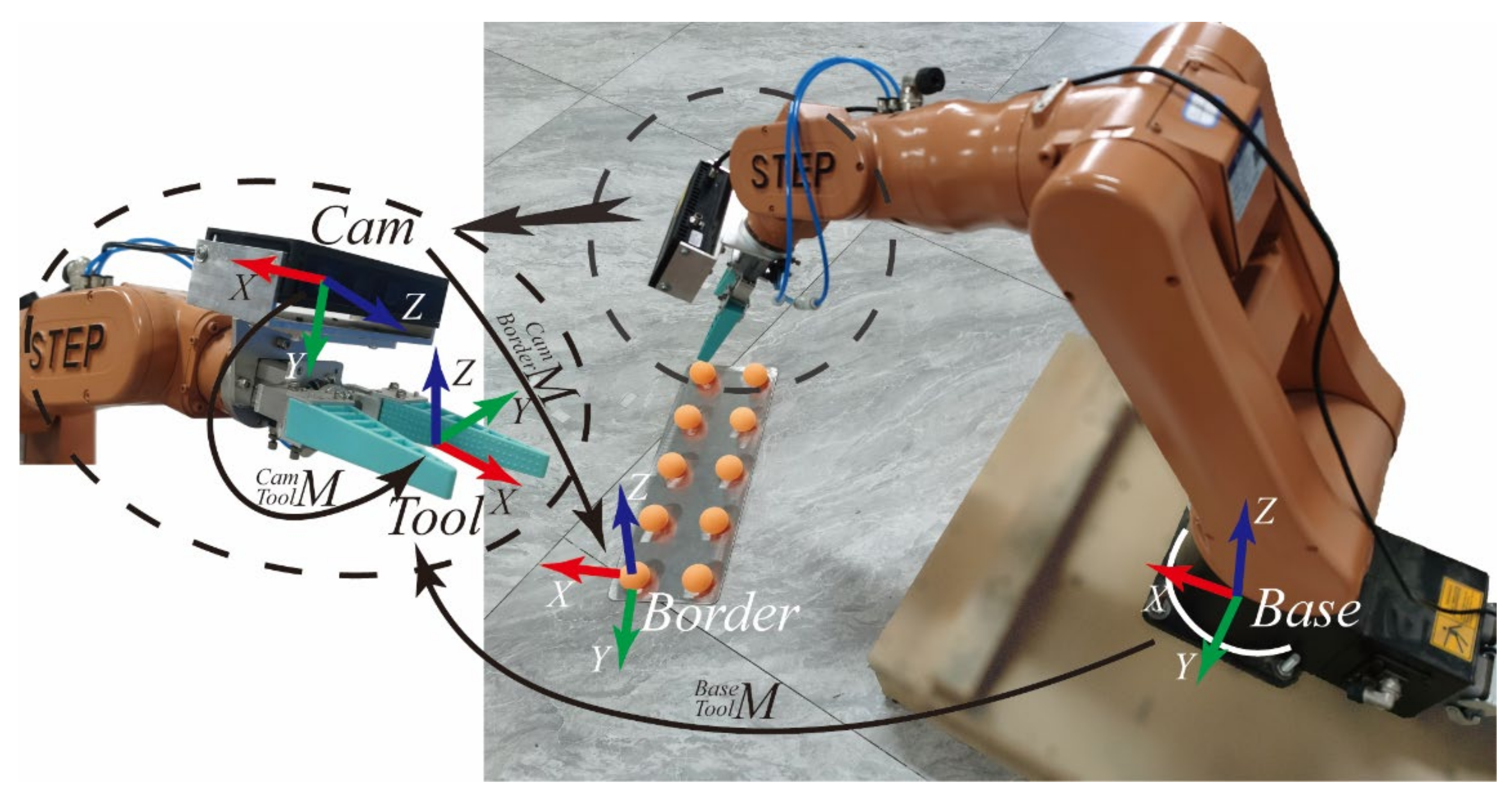
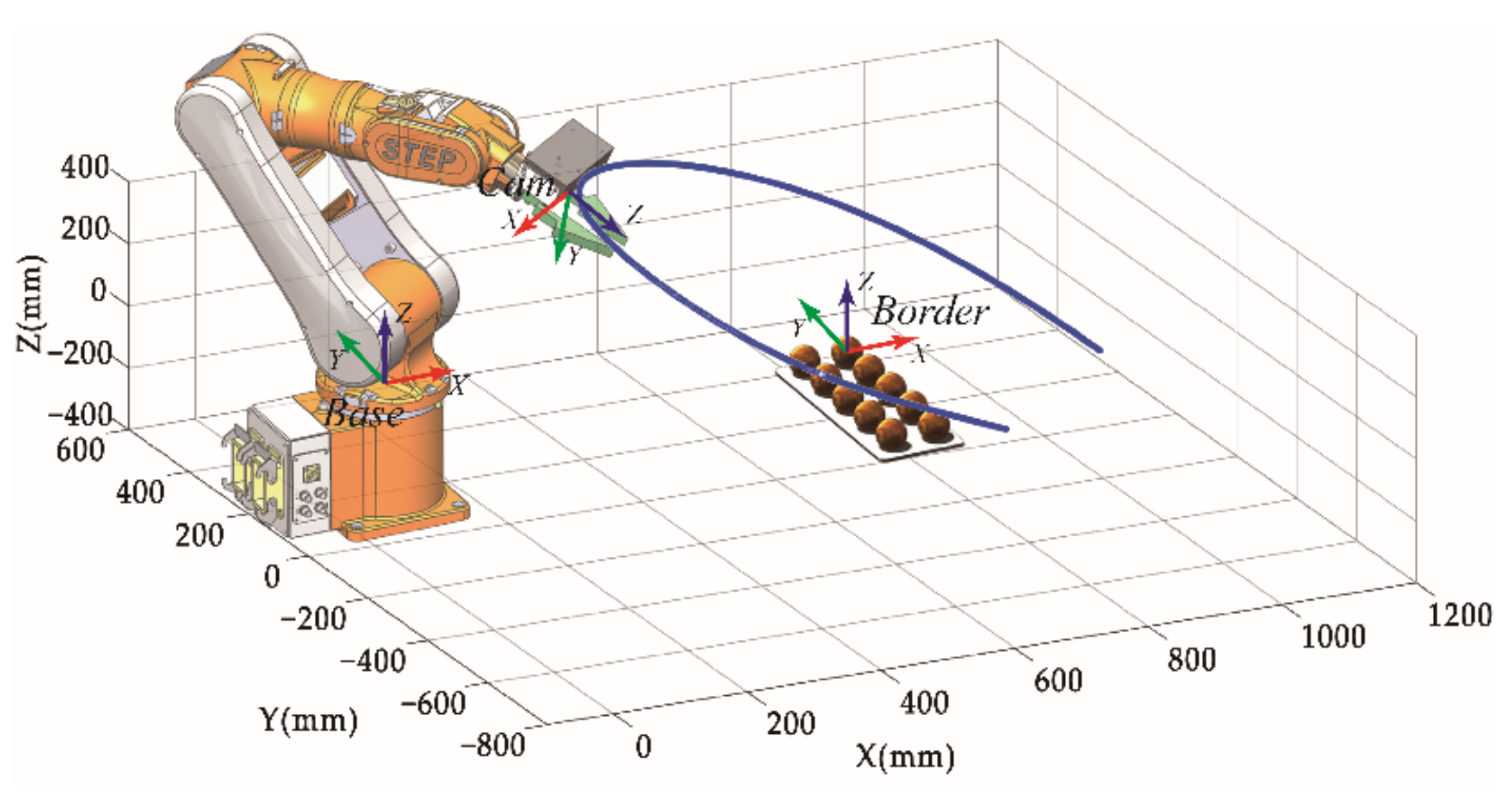
In order to achieve rapid self-calibration of the vision system and rapid target positioning, this paper builds a robotic arm system shown as Figure 1. The system mainly includes the manipulator, end-effector, RGB-D camera and table tennis calibration board. The depth image acquisition device we use consists of two symmetric infrared (IR) cameras. The depth image is computed from the parallax of the dual IR cameras and combined with the RGB camera to generate a point cloud image with texture information.

Figure 1.
Vision guided intelligent robot system.
The experimental platform uses a STEP-SD500E six-axis robotic arm (repeatable positioning accuracy ±2 mm) with a pneumatic end-effector to form a robotic system. The camera uses the Percipio-FM830 RGB-D camera, which consists of an infrared (IR) projector, two IR cameras and an RGB camera. The IR projector with IR camera forms a binocular camera to acquire Depth images, and each pixel represents the distance from the camera to each point in the scene. The monocular RGB camera acquires RGB images. The acquisition error of the RGB-D camera is 0.2%~1% of the shooting distance. The image resolution is 1280 × 960.
As shown in Figure 2, the system process can be divided into three stages: (1) in the self-calibration stage of the manipulator hand-eye system, the image acquisition path planning is automatically planned based on the quaternion spherical linear interpolation method and the image of the calibration board is collected to solve the calibration parameters; (2) the point cloud hole completion stage is based on the point cloud rapid registration method of the iterative manipulator shooting pose space coordinate conversion to complete the point cloud reconstruction of the outer surface of the object; (3) the point cloud instance segmentation stage uses the improved double pyramid feature fusion depth image to segment the RGB image through Mask R-CNN, and maps it to the point cloud space to achieve point cloud instance segmentation.
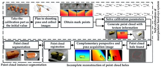
Figure 2.
The algorithm flow.
3.1. Hand-Eye System Self-Calibration
The RGB-D camera used in this paper consists of an RGB camera and a depth camera, which can obtain depth images and RGB images, respectively. As the RGB camera and the depth camera are not in the same position in space, camera calibration is necessary to unify the reference systems of the two images and obtain the conversion relationship between the image coordinate system and physical coordinate system. The RGB camera is used as a reference for hand-eye calibration and completes calibration of the hand-eye system.
As both the depth map and the RGB map are more sensitive to the contour of the three-dimensional object. A three-dimensional calibration object needs to be made, because ping pong balls are very easy to obtain, and the size is appropriate. The balls need to be spaced in a certain viewing angle to ensure that they are not blocked from each other. This paper uses the self-made table tennis array as shown in Figure 3 as the three-dimensional calibration object. The diameter of each ping pong ball is 40 mm and the spacing is 90 mm.
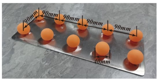
Figure 3.
Three-dimensional calibration object.
The path is automatically planned for the camera to shoot the calibration parts, and multiple sets of calibration pictures are collected. The center coordinates of the ping-pong ball under RGB and depth images are detected by Hough transform, and the two sets of linear overdetermined equations are solved to obtain the internal and external parameters and hand-eye calibration matrix of the camera.
3.1.1. Automatic Acquisition of Calibration Images Based on Spatial Spherical Interpolation
This paper proposes an automatic path planning algorithm based on quaternion Slerp space spherical linear interpolation. Given two initial shooting poses, the continuous shooting path S can be automatically planned, and multiple pictures of the calibration parts shot at different angles can be collected.
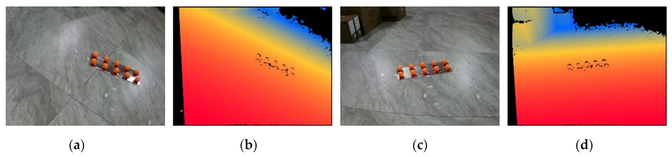
As shown in Figure 4, the two manipulator postures and are manually set as initial values through the teach pendant, so that the calibration parts and are in the middle of the field of view of the RGB image and the Depth image.

Figure 4.
Image of initial pose calibration parts: (a) RGB map of pose A; (b) depth map of pose A; (c) RGB map of pose B; (d) depth map of pose B.
It is also possible to use an external global camera to obtain the position of the calibrator to automatically calculate the initial value, but this increases the hardware cost and complexity of the operation.
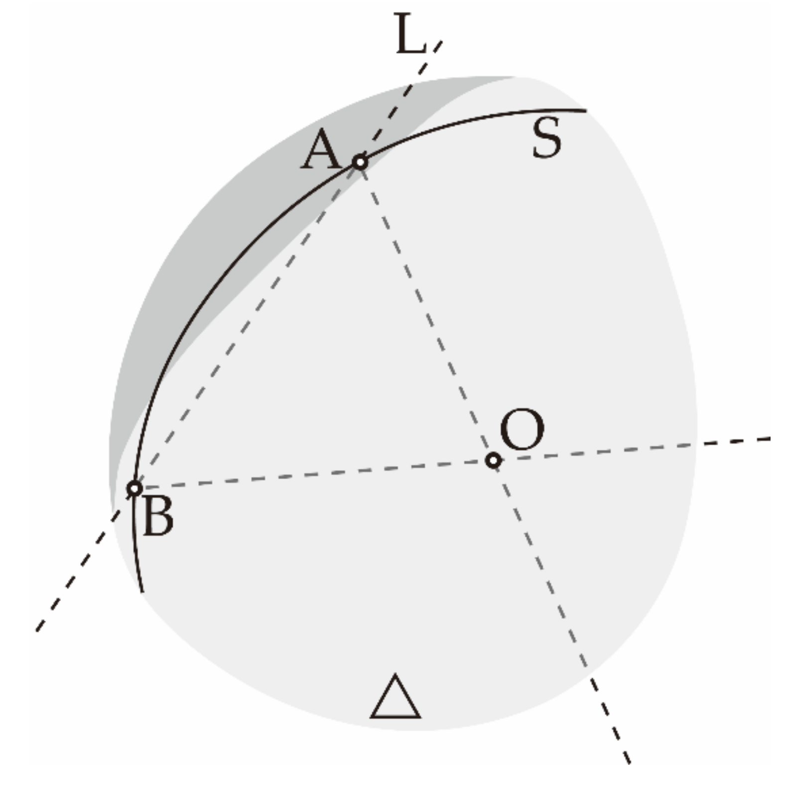
As shown in Figure 5, after the initial value poses A and B are located at the space point , the intersection of the direction pointed by the manipulator end is set as the center of the circle to make the spherical surface . Let the intersection of L and the range of movement of the manipulator end-effector is . Connect to get a straight line , project it on , and achieve a space curve . Then the two ends of the record pointing to the center of the sphere are the poses and , and interpolate the image acquisition pose of pointing to the center of the sphere , and they are each spatially symmetric about the calibrator.
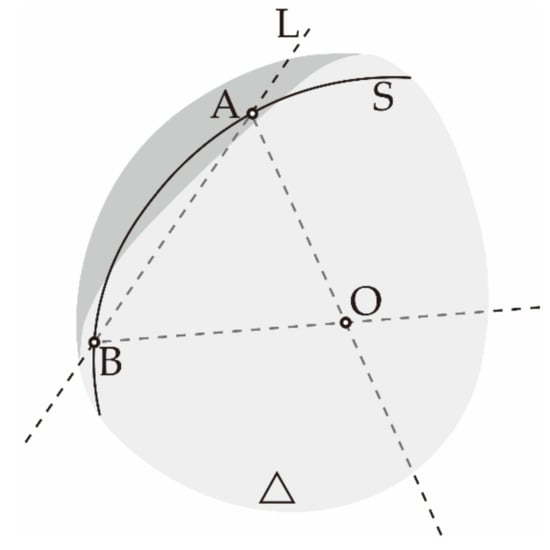
Figure 5.
Schematic diagram of acquisition curve L.
Make the transformation of posture to posture , the coordinates () of the center of posture is under . The direction of the x-axis, y-axis and z-axis of posture can be expressed by vectors, which are the mutually orthogonal unit vectors () in . Define the rotation matrix R as:
The end pose M of the robot is composed of translational freedom T and rotation freedom R. Because they are two different units of quantities, the normalization method cannot be used for simultaneous planning. Therefore, the position and posture need to be planned separately, and then synchronized. The augmented matrix synthesized by T and R is easy to send singular solutions in the special pose of the manipulator, so a quaternion is introduced to represent the robot posture to avoid singularity [39].
Convert Equation (1) to a unit quaternion through Equation (2):
The unit quaternion and the quaternion in the same direction have the same rotation function, thereby the quaternion can be used to plan the direction of the path, and the position matrix T can be used to plan the position.
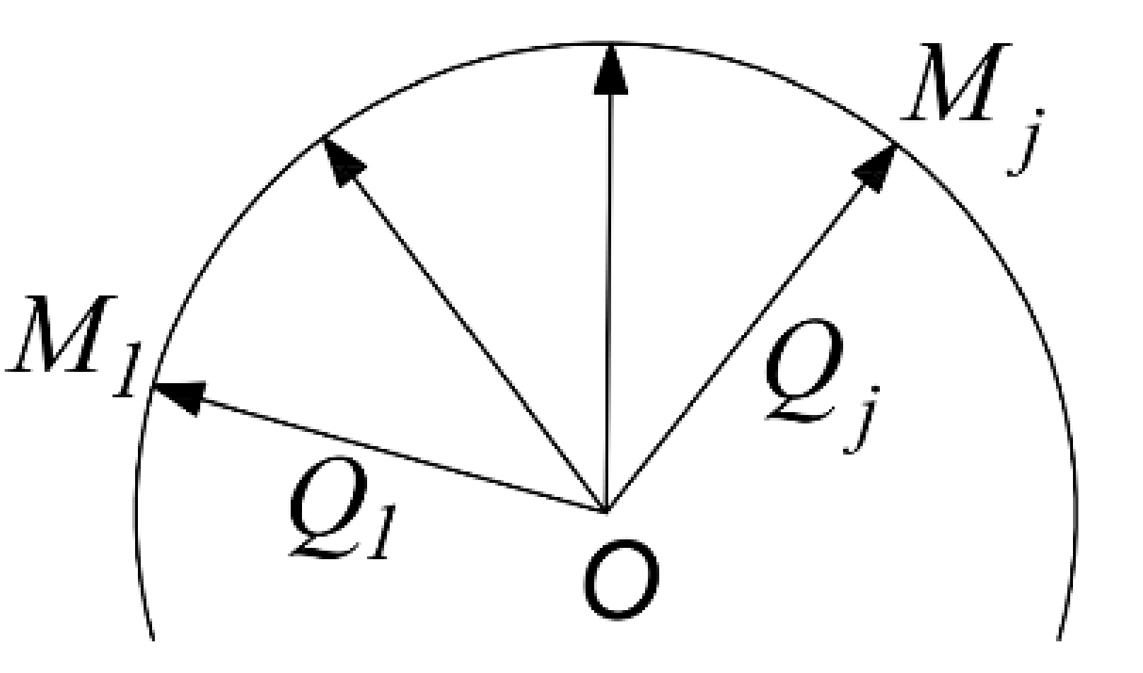
As shown in Figure 6, the directions of the end-point poses and of the feasible region are represented by quaternion as and , and the path is planned by Slerp interpolation [40] along the space curve S.

Figure 6.
Slerp interpolation.
The Slerp function of the quaternion interpolation of the -th point unit can be obtained:
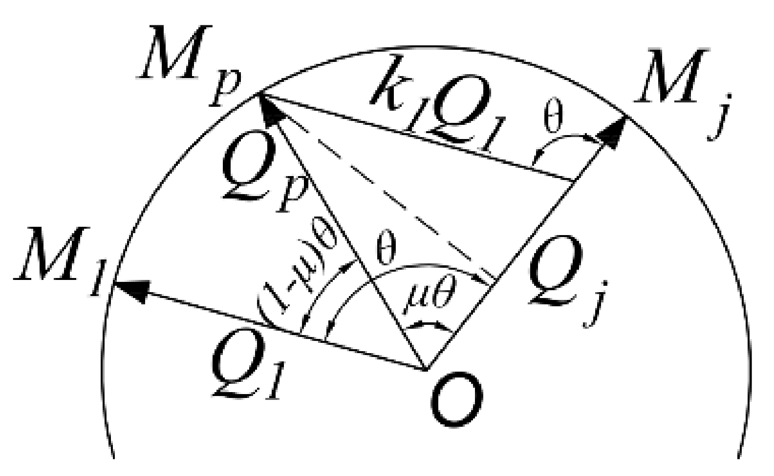
In the process of real-time interpolation and image acquisition, each frame taken continuously shall be consistent with the mechanical pose of the frame as far as possible. Thereby, it is necessary to avoid time-consuming calculations such as power, inverse and multiplication of quaternion. Equation (4) can be obtained from several relationship in Figure 7, and is the angle between quaternions and .
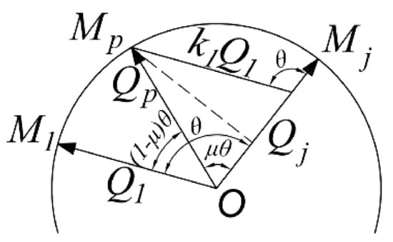
Figure 7.
Derivation of Slerp interpolation formula.
Similarly, can be solved. The -th pose pointing to the center of the sphere can express the scale coefficient as:
Slerp interpolation formula (3) is rewritten as:
In Equation (6), there are only number multiplication and addition with small calculation amount, and it can maintain high real-time performance with the camera for continuous shooting.
3.1.2. Calibration Data Processing Method
On the movement curve S, image acquisition poses are selected to obtain the key frames of RGB and Depth images. The coordinates of the center of the sphere are extracted through the Hough circle detection algorithm, as shown in Figure 8.
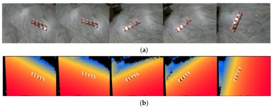
Figure 8.
Calibration image key frame: (a) RGB images; (b) depth images.
Using Zhang Zhengyou calibration method, the internal parameter matrix and distortion coefficient of RGB camera, the internal parameter matrix and distortion coefficient of depth camera are calculated respectively. After the distortion coefficient is used to repair the image distortion, the RGB image is fused with the depth image through Equation (7), so that each pixel of the RGB image corresponds to a depth value.
where, is the space point converted from the world coordinate system to the color coordinate system; is the external parameter matrix from the world coordinate system to the color camera coordinate system; is the external parameter matrix from the depth camera coordinate system to the color camera coordinate system; is the point from the depth map to the world coordinate system; is the external parameter matrix converted from the world coordinate system to the depth camera coordinate system, and is the three-dimensional point coordinate of a point in the depth map of the depth camera coordinate system.
After fusing the depth values, 4 channels of data are obtained, which are three color components and one depth component, and then a textured point cloud image can be constructed.
Taking the RGB camera as the reference, the pose sequence of the calibration part under camera coordinate systems by locating the center point of the calibration plate is obtained. Corresponding to the pose sequence of the manipulator end-effector during shooting, the hand-eye calibration matrix is calculated by Equation (8).
where, as the calibration part is fixed relative to the coordinate system , and is constant; is obtained by the image algorithm through each shot of the calibration part, and can be obtained by reading the manipulator teach pendant.
can be obtained by solving Equation (8), and the hand-eye calibration matrix can be obtained through Equation (9).
Generally, given only two initial shooting values, the calibration parameters of RGB-D camera can be automatically calculated by this algorithm, and the textured point cloud can be generated by integrating RGB and depth data, to finally realize the hand-eye calibration of manipulator and RGB-D camera.
3.2. Fast Point Cloud Registration
The point cloud image obtained by photographing the target in the scene with RGB-D camera usually forms the point cloud hole in the blind area of field of vision as shown in Figure 9. This results in reconstruction failure and is unable to provide accurate pose information of the target for subsequent grasping, dispensing and assembly. Thus a point cloud hole filling shooting method is proposed, and fast point cloud registration is conducted.
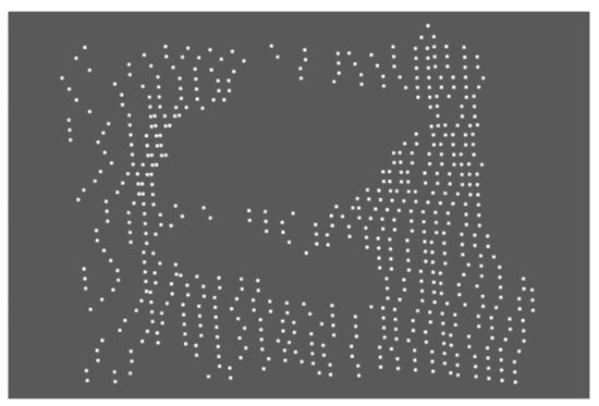
Figure 9.
Lack of visual blind area in point cloud.
3.2.1. Pose Calculation of Point Cloud Hole Completion Shooting
- 1
- Hole discrimination:
KD tree with strong adaptability, low memory consumption and not affected by point cloud density is used to establish the topological relationship of point cloud. The Euclidean distance from the sampling point to its adjacent points is calculated. The point whose distance is less than the given hole repair threshold is determined as the boundary point of the hole.
Firstly calculate the average density of the point cloud. points are randomly selected from the sample as feature points to obtain the feature point set , and . KD tree is used to traverse each point in the point cloud to find the k points with the smallest distance from it. Calculate the distance between K adjacent points and , and average all to obtain the point cloud density . The hole threshold is obtained from the point cloud density by specifying the threshold coefficient .
Then K neighborhood search is used to traverse all points of the point cloud, find the points closest to them, and calculate the distance between this point and points, . Once a distance in sequence is greater than the hole threshold , the point is considered as a boundary point and saved in the boundary point set .
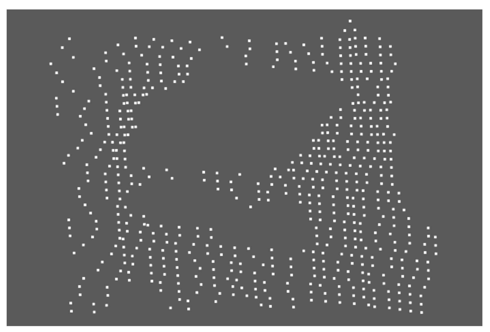
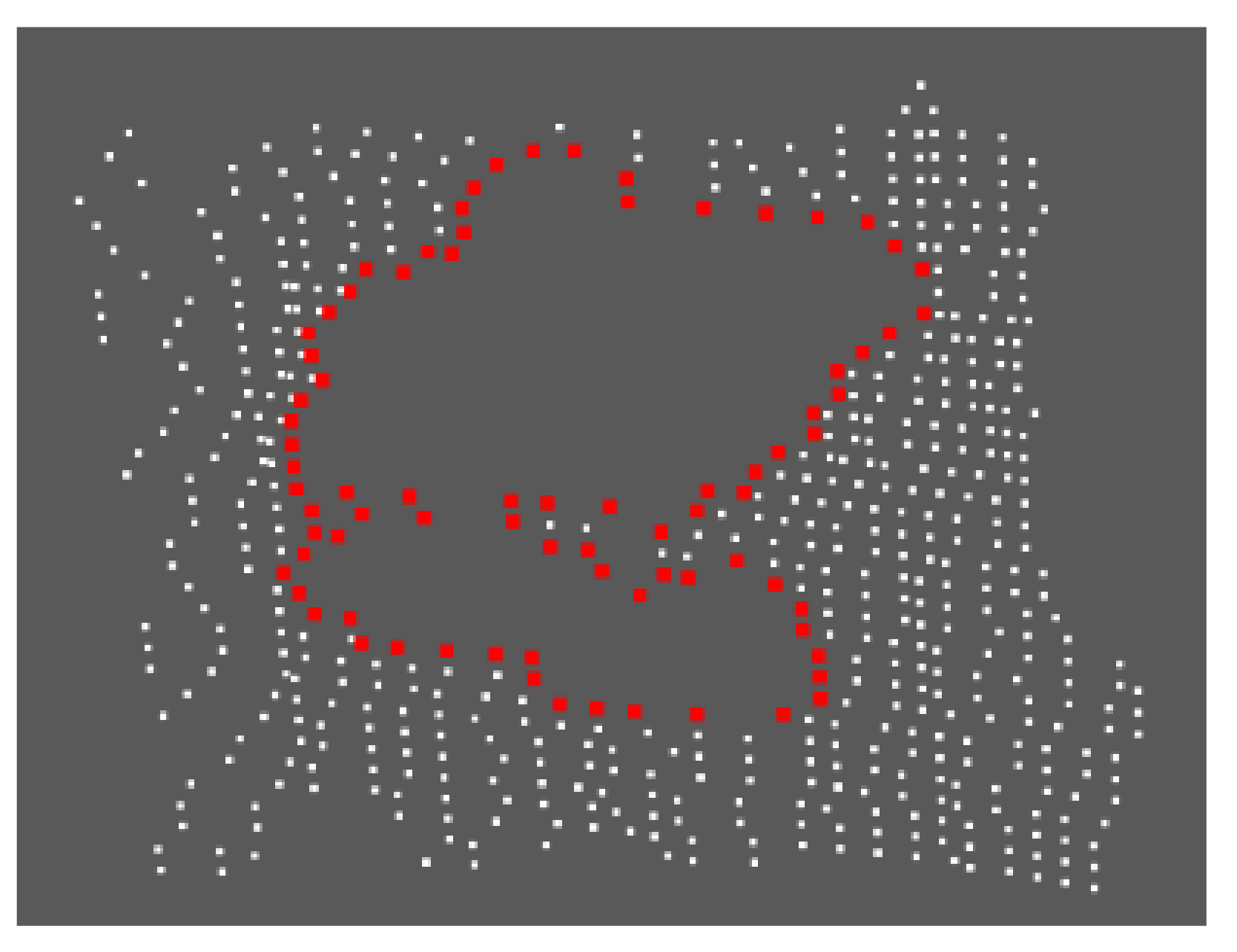
After the boundary point set is obtained, the boundary is further extracted. Using the K neighborhood search method, K adjacent points of is found to obtain the boundary and calculate the pose of each hole. Where n is less than or equal to the number of holes, and the local hole boundary detection effect is shown in Figure 10.

Figure 10.
Local hole boundary detection effect.
- 2
- Complementary image shooting pose calculation:
After knowing the pose of the hole compared with the object , it is necessary to automatically plan the manipulator to move to the appropriate pose to supplement the blind area of the field of view collected for the first time. Take the coordinate of a point on the object as , the first shooting pose as , as the center of the circle and as the radius to make the spherical surface . Note that the intersection of and the activity range of the manipulator end-effector is . The normal plane composed of the missing hole contour of the point cloud is moved to the spatial sphere through the translation matrix .
Convert it to the manipulator shooting pose through the following formula:
Repeat the above process, and stop if one of the following conditions is met: (1) the missing hole has no intersection with the feasible region of the manipulator after moving through the translation matrix, i.e., the manipulator cannot move to the supplementary image shooting pose due to its mechanical structure; (2) no holes that meet the requirements, i.e., the holes in the working part of the model are supplemented and meet the requirements; (3) when the set upper limit of image acquisition is reached, image acquisition is stopped.
3.2.2. Registration of Complementary Point Clouds
According to the position relationship of the manipulator under different shooting angles, the point cloud coarse registration is carried out for the collected multi-frame data, and then the ICP algorithm is used for the fine registration of coarse registration results. After multiple sets of point cloud data are registered, the point cloud is too dense and redundant, and downsampling algorithm is needed to remove redundant points.
- (1)
- Coarse registration of point cloud based on manipulator pose: Record the pose of the manipulator when collecting images, and obtain the pose of the camera through the hand-eye calibration matrix .
The initial point cloud data collected each time is moved to the coordinate system through rigid body transformation, so that the point cloud coordinate system coincides with the base system and satisfies,
where, and are the coordinates in the coordinate system before and after the point cloud conversion.
- (2)
- The steps of point cloud fine registration based on ICP algorithm are as follows:
Step 1: Convert the point cloud collected for the first time to the coordinate system through Equation (13) to obtain ;
Step 2: Convert the point cloud collected for the time to the through Equation (13) to obtain . Then ICP algorithm is used to register to based on and fuse into ;
Step 3: Repeat Step 2 until all complementary point clouds are registered to obtain a composed of multiple complementary point clouds.
- (3)
- Downsampling of point clouds
After multiple sets of point cloud data registration, although some holes are filled, it also causes the redundancy of point clouds in overlapping areas. It is not conducive to the segmentation of point clouds. In this paper, a method based on geometric sampling is proposed to the downsampling of the registered point cloud to obtain point cloud data with uniform density. This not only reduces the amount of invalid data, but also retains the details of the model.
Firstly, the k-nearest neighbor point cloud around each point cloud is approximately in a local plane. The implicit surface equation obtained by least square fitting is , and then the Gaussian curvature K at point is calculated as follows:
where, is the gradient corresponding to the implicit equation at ; is the Hessian matrix describing the local curvature of the function, and is the adjoint matrix of .
The given point cloud model is represented by , and the point set of iterative farthest point sampling can be expressed as . Assuming that the current sampling is point j, the next sampling point should be point m that farthest from point j, and m satisfies:
where, is the distance between two points. It can be seen from Equation (15) that the fusion of Euclidean distance and curvature can sample more model details, and
where, is the curvature of m, and is the weight set to balance Euclidean distance and curvature.
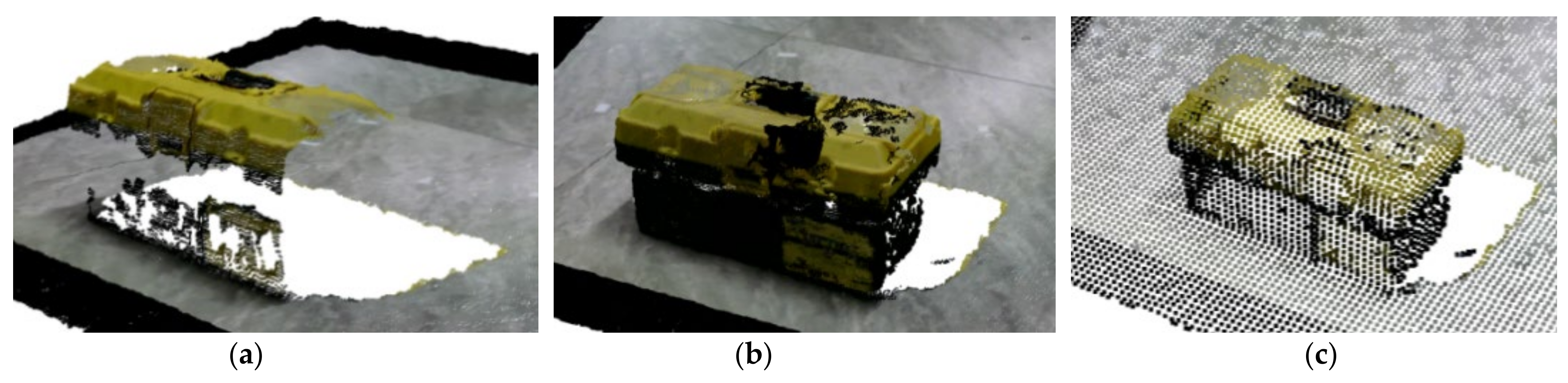
Figure 11a is a point cloud image with multiple holes generated by the viewing angle blind area acquired for the first time; Figure 11b is the point cloud model after complementary point cloud registration, which completes the point cloud model within the activity range of the robotic arm. Figure 11c is a sparse point cloud model that can accurately express the shape of an object after geometric sampling, and it also can save computational resources for subsequent operations.
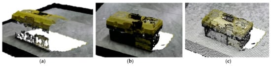
Figure 11.
Point cloud processing: (a) original point cloud; (b) complementary point cloud registration results; (c) sparse point cloud model.
3.3. Point Cloud Instance Segmentation
Presently, the traditional point cloud segmentation methods cannot segment the point cloud in multiple scenes. As multi-dimensional information, the huge data structure and chaotic distribution of point cloud also bring great difficulties to the data annotation of deep learning. Thus RGB-D image acquisition equipment provides us with new ideas. The RGB image is used to fuse the depth image for two-dimensional input, and the Mask-RCNN is improved by using their sensitive characteristics to the object boundary. It not only facilitates the annotation training, but also increases the accuracy of segmentation. The RGB segmentation results of the fusion segmentation are obtained and mapped to the point cloud space to achieve point cloud segmentation.
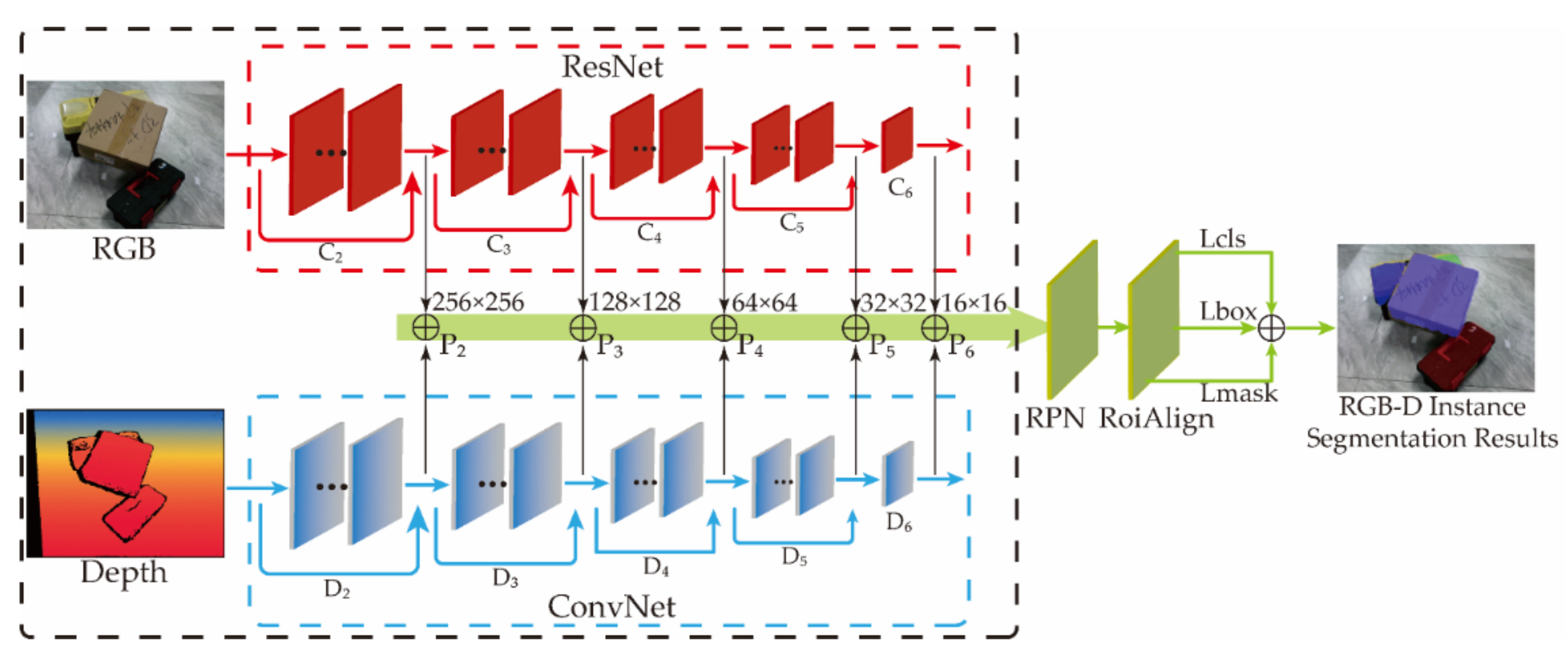
In order to better combine the complementary advantages of RGB and depth images, this paper proposes a double pyramid feature fusion network, which uses convolutional networks of different complexity to extract RGB and depth features, respectively.
The residual network with a deeper network layer is used to extract the features of RGB images, and the network branch with a smaller number of layers is used to extract the features of depth images. As shown in Figure 12, the image pyramid is used in the feature extraction stage to save RGB and depth features of different resolutions. RGB features with the same resolution are added with depth features, and then input them the into RPN (region proposal network) layer. The header structure network segment of Mask-RCNN forms a double pyramid feature fusion network to realize multi-class instance segmentation of RGB-D images.

Figure 12.
Block diagram of the dual pyramid feature fusion network model.
Studies have shown that the feature maps at the top of the image pyramid will contain richer semantic information, but the corresponding location information is less accurate. Although low-level feature maps contain less semantic information, the location information is more accurate [41]. In this paper, the application more focuses on the accurate extraction of location information. Depth information is more effective in position detection tasks, and the results of semantic detection are inaccurate in most cases. Therefore, the use of RGB images and depth images at the same time can achieve the enhancement effect of two features. The high-level RGB features contain rich semantic information, and the low-level depth features contain accurate location information. This requirement can be met by fusing the relatively low-level depth feature with the RGB feature of the same resolution and inputting it into the shared feature map of RPN.
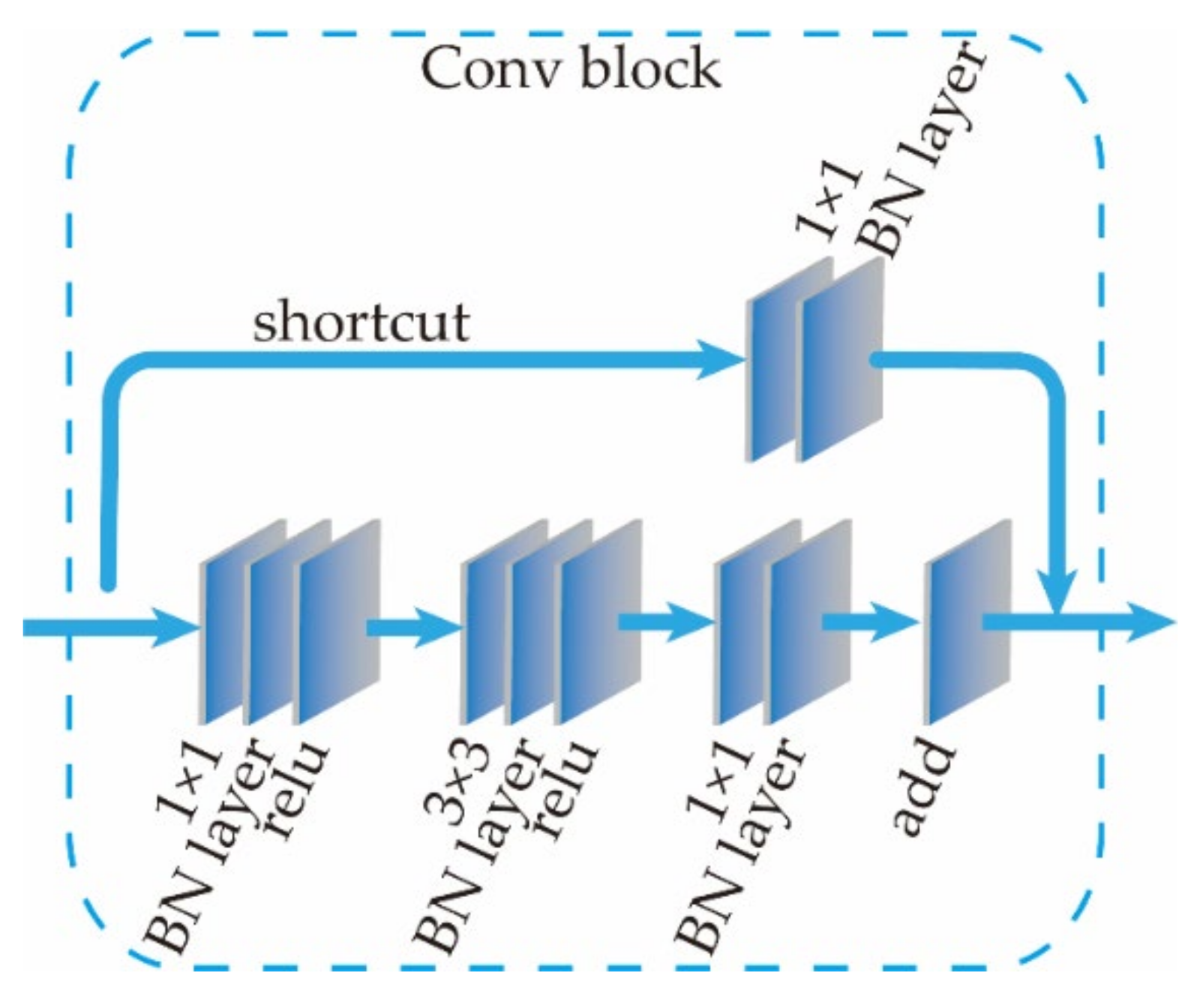
Based on the above inference, in order to achieve the effect of making full use of depth information, the same residual network as the RGB branch cannot be used. Referring to the structural design of residual network convolution module [42], the depth feature maps of different resolutions are extracted through multiple convolution blocks, and the structure of one convolution block is shown in Figure 13.
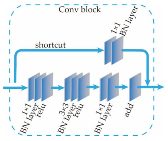
Figure 13.
Convolution block structure diagram.
The main structure of the convolution block contains three convolution layers, and the shortcut connection network path contains a single convolutional layer and a single BN layer. The size of the convolution kernel is 1 × 1, and the step size is 2. The input depth feature map passes through a convolution block model, and its size is one-fourth of the original. A structure similar to this module in the residual network structure of RGB features is extracted, but it contains many deep residual block models. Hence, for the feature map with the same resolution, the Depth image undergoes fewer convolution operations, and the extracted features are lower than the RGB features. This conforms to the RGB feature-guided semantic segmentation, and the depth feature perfects the target of position detection.
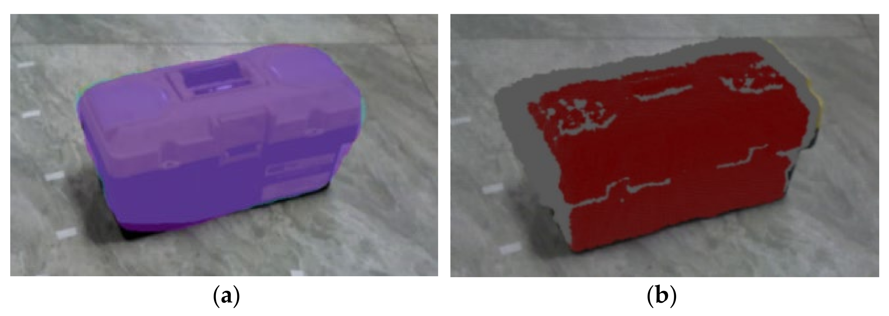
The instance segmentation result under RGB image obtained by the algorithm finally is shown in Figure 14a, which indicates that the toolbox is more accurately marked in the image. The marked ROI (region of interest) is mapped to the point cloud space, and the point cloud of the toolbox is segmented from the point cloud image, as shown in Figure 14b with a red point. The segmentation results meet the expectations of the algorithm design.

Figure 14.
Instance segmentation effect: (a) instance segmentation effect of RGB image; (b) instance segmentation effect of point cloud.
4. Results
The experiment consists of four parts: (1) self-calibration experiment of the hand-eye system of the manipulator to verify the influence of sampling points K on the calibration accuracy; (2) point cloud rapid registration experiment to verify the accuracy and time of point cloud registration and fusion in different posture; (3) point cloud segmentation experiment, use the Mask-RCNN network fused with depth information to segment the point cloud, and compare the segmentation effects before and after the improvement; (4) reconstruction and positioning accuracy analysis to verify the overall accuracy of the hand-eye system and algorithm in this paper.
The experiment settings are as follows: The experimental platform consists of STEP-SD500E six-axis manipulator (repetitive positioning accuracy ±0.02mm) and Percipio-FM830 structured light camera (the error is 0.2%–1% of the distance, 13 FPS) (as shown in Figure 1). The diameter of the ping-pong ball used for the calibration piece is 40mm, and the spacing between each ping-pong ball is 90 mm, forming a 2 × 5 matrix calibration piece (as shown in Figure 3). The computer CPU is i5-10500H with a main frequency of 2.5 GHz.
4.1. Self-Calibration Experiment of the Manipulator Hand-Eye System
Two initial pose values A and B are specified. The calibration path obtained by Equation (6) is shown in Figure 15, and image acquisition on the calibration part is carried out. The number of actually collected images has a certain impact on the calibration accuracy. Experiments are conducted to determine the appropriate p-value by giving a different number of sampling points p.
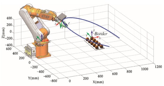
Figure 15.
Shooting pose.
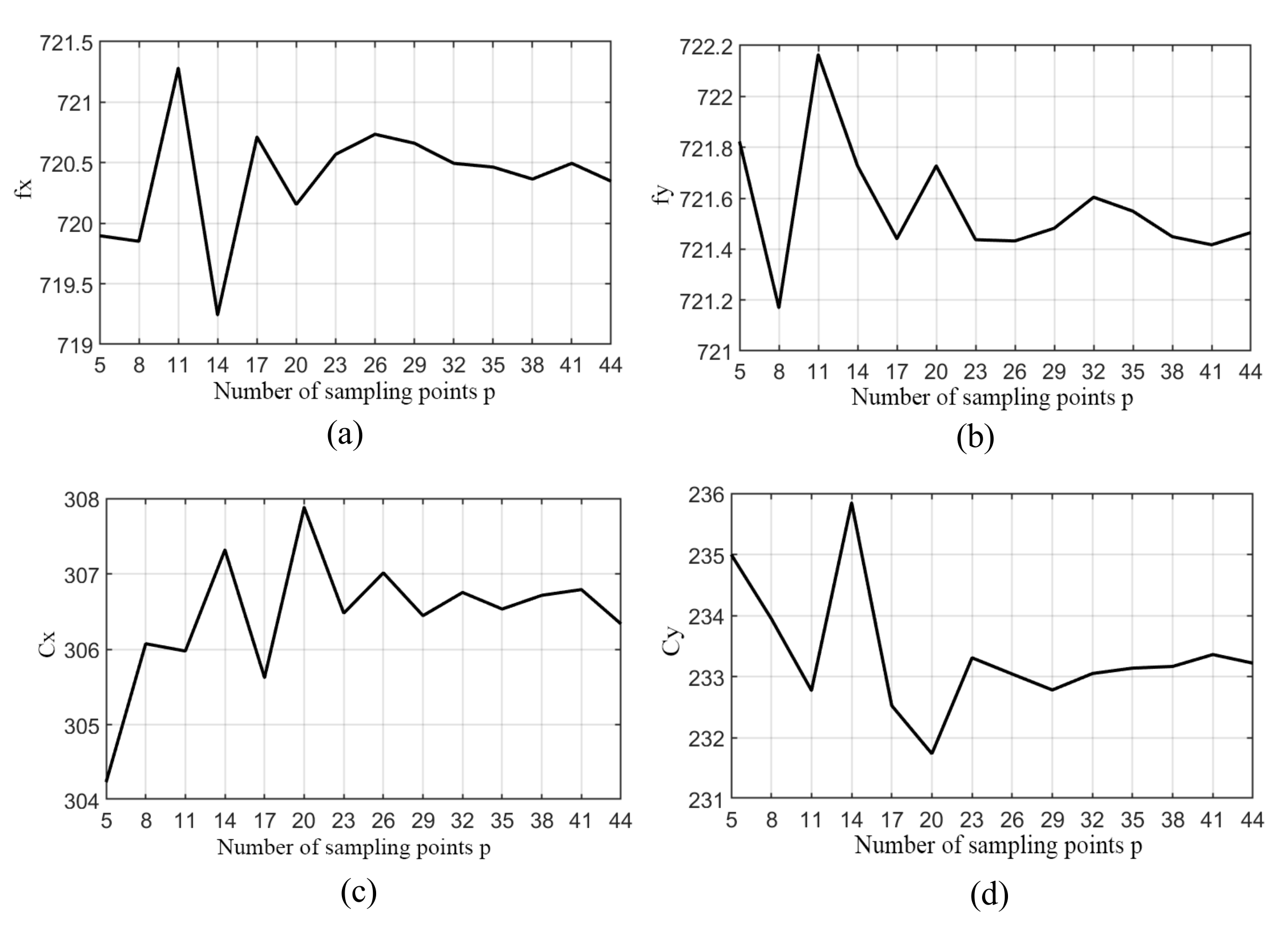
If the motion speed of the manipulator is set to be constant, the processing of the calibration image is carried out by the algorithm in the background, and the difference in time depends on the number of calibration images. The sampling points p = 5, 8, 11, 14, 17, 20, 23, 26, 29, 32, 35, 38, 41, 44 between A and B are selected for calibration test respectively, and the variation curve of internal parameters Fx, Fy, Cx and Cy of RGB camera with sampling points p is obtained as shown in Figure 16.
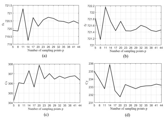
Figure 16.
The relationship between the p-value of the sampling point and the calibration result: (a) The internal reference Fx varies with value p of the sampling points; (b) the internal reference Fy varies with value p of the sampling point; (c) the internal reference Cx varies with Value p of the sampling point; (d) the internal reference Cy varies with Value p of the sampling point.
It can be seen from Figure 16 that when the sampling point p is small, the fluctuation of each parameter is more obvious. When the sampling point p reaches about 23 frames, each calibration parameter gradually stabilizes.
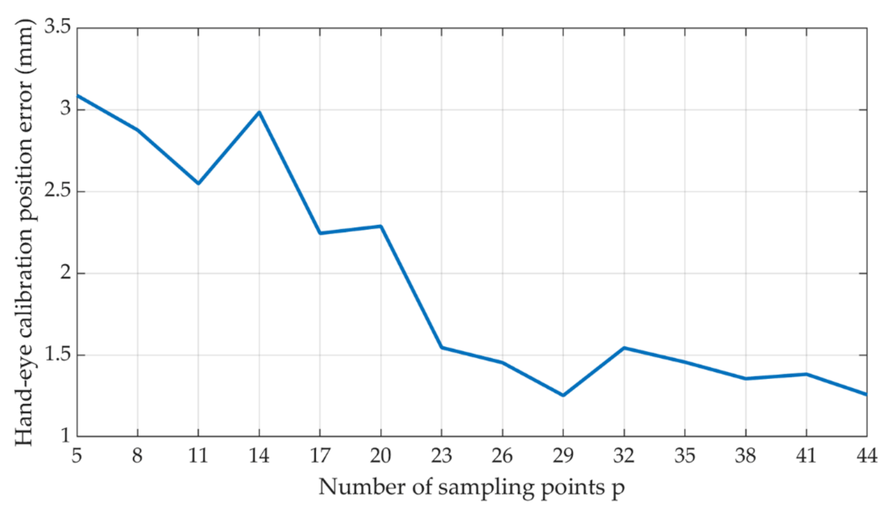
The spherical coordinates are used as data for solving the linear system of equations in calibration algorithm, and they are inevitably subject errors. In order to verify the accuracy of the calibration, the camera shooting poses are inverted by the poses of each group of the calibration objects, and the robotic arm poses are obtained from Equation (9). As shown in Figure 17, the calibration position error of the hand-eye system to the sampling point p-value is related, which is obtained by comparing each set of real shooting poses with the inverse-sought shooting poses.

Figure 17.
The relationship between the p-value of the calibration position error of the hand-eye system.
It can be seen from Figure 17 that when the sampling point p is small, the calibration error is larger. When the sampling point p reaches about 23 frames, the calibration error of the hand-eye system is less than 2 mm. This tends to be stable and close to the acquisition accuracy of the camera.
4.2. Point Cloud Reconstruction Experiment
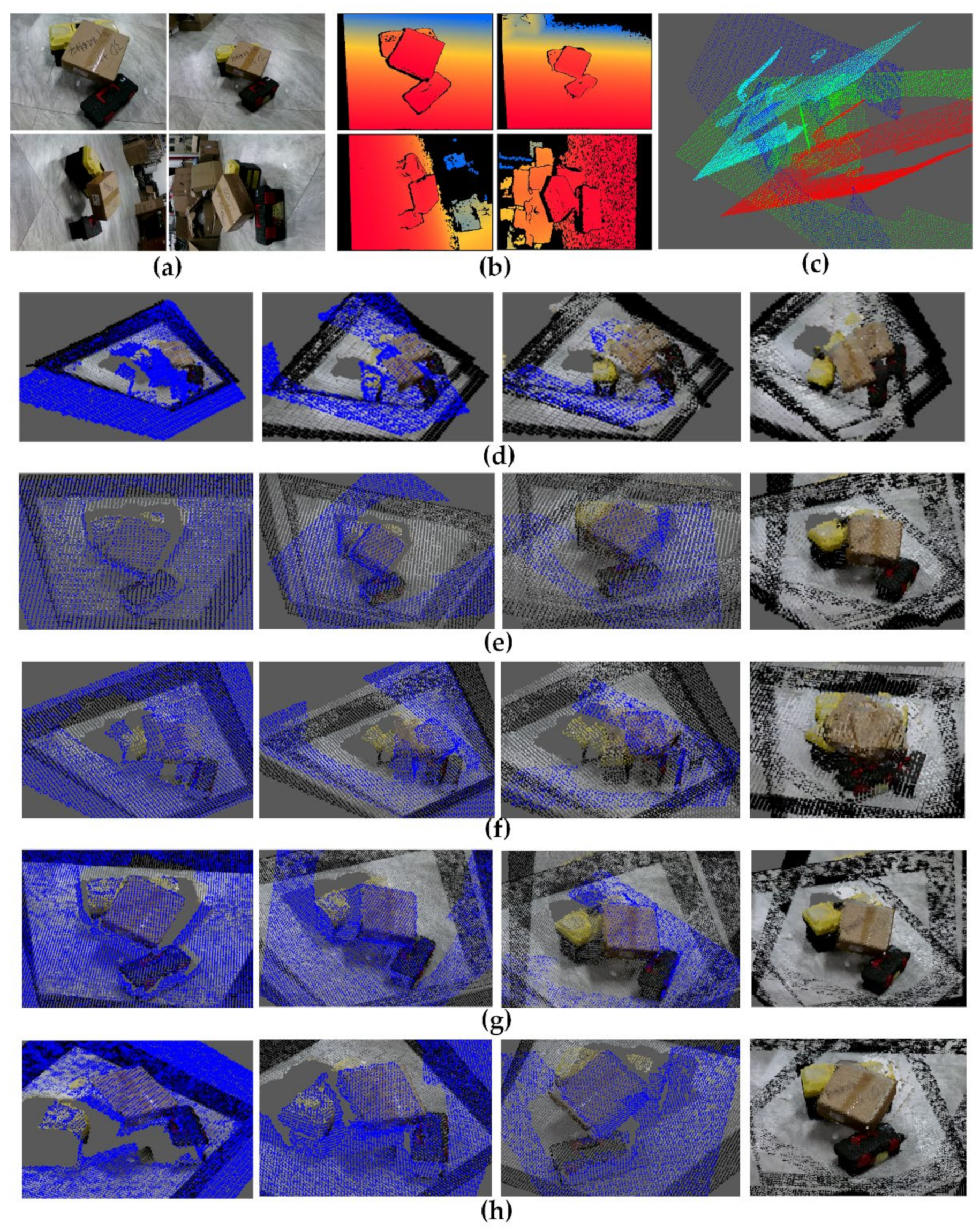
In the experiment, several objects with different poses and stacks are selected to test the registration and reconstruction effects of the algorithm in this paper and compare them with the classic registration algorithm. Because it needs to fuse multiple point clouds from different angles, and an iterative registration method is adopted to register the two point clouds after fusion and then register with the next point cloud. In this paper, several classical coarse registration algorithms with the precision registration algorithm ICP are chosen as a control group. Four complementary shooting pose images are taken in the experiment, thus three times of registration is required. The iterative registration results are shown in Figure 18 and the time-consuming is shown in Table 1. The error statistics of the registration results for each algorithm are shown in Figure 19.
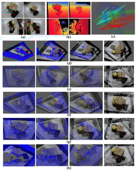
Figure 18.
Iterative registration results: (a) original RGB data; (b) original depth data; (c) original point cloud data; (d) PFH with ICP; (e) 3Dsc with ICP; (f) NDT with ICP; (g) algorithm proposed in this paper (precision registration with ICP); (h) algorithm proposed in this paper (no precise registration).

Table 1.
Time-consuming of each algorithm.

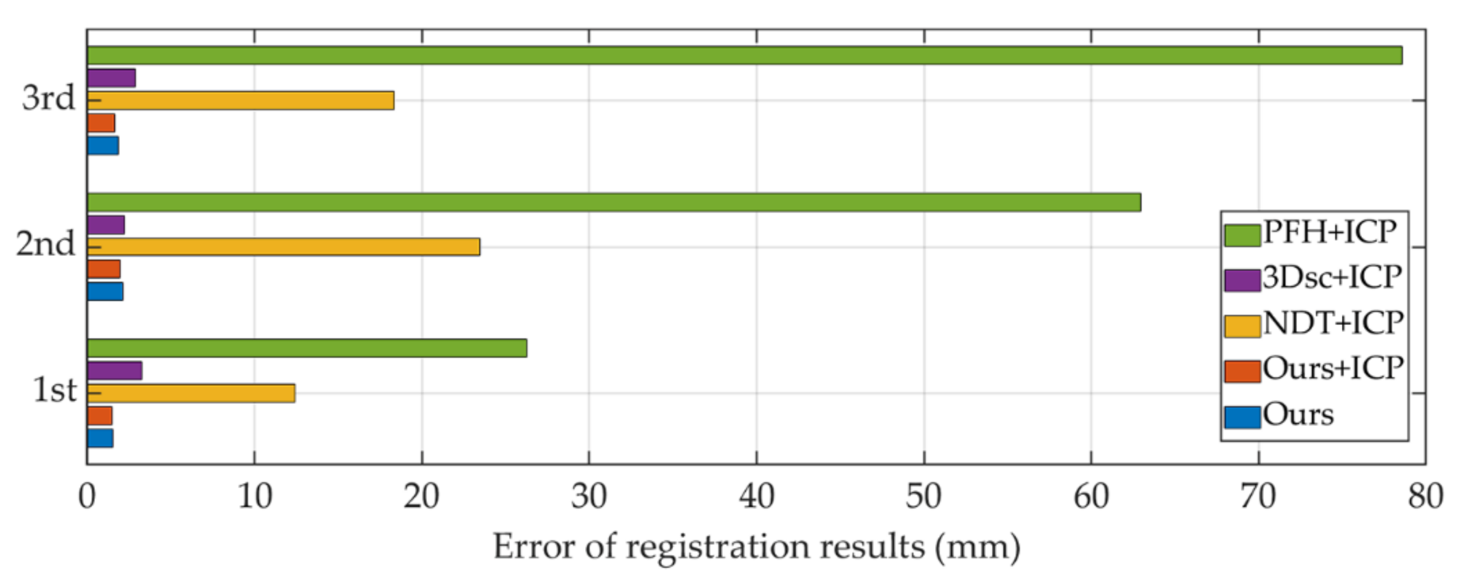
Figure 19.
Error of registration results.
It can be seen from Figure 18c that the point clouds taken from different angles cannot be directly fused in the same coordinate system, and the fusion of complementary point clouds must be realized through the point cloud registration algorithm. As shown in Figure 18g and Figure 19 and Table 1, the registration results of the algorithm in this paper are accurate and the maximum error does not exceed 2 mm. The algorithm in this paper is more economical in computational resources than the compared algorithms.
4.3. Point Cloud Segmentation and Precision Experiment
Several commonly available items are selected and tested under independent and stacking conditions to test the point cloud segmentation effect and positioning accuracy.
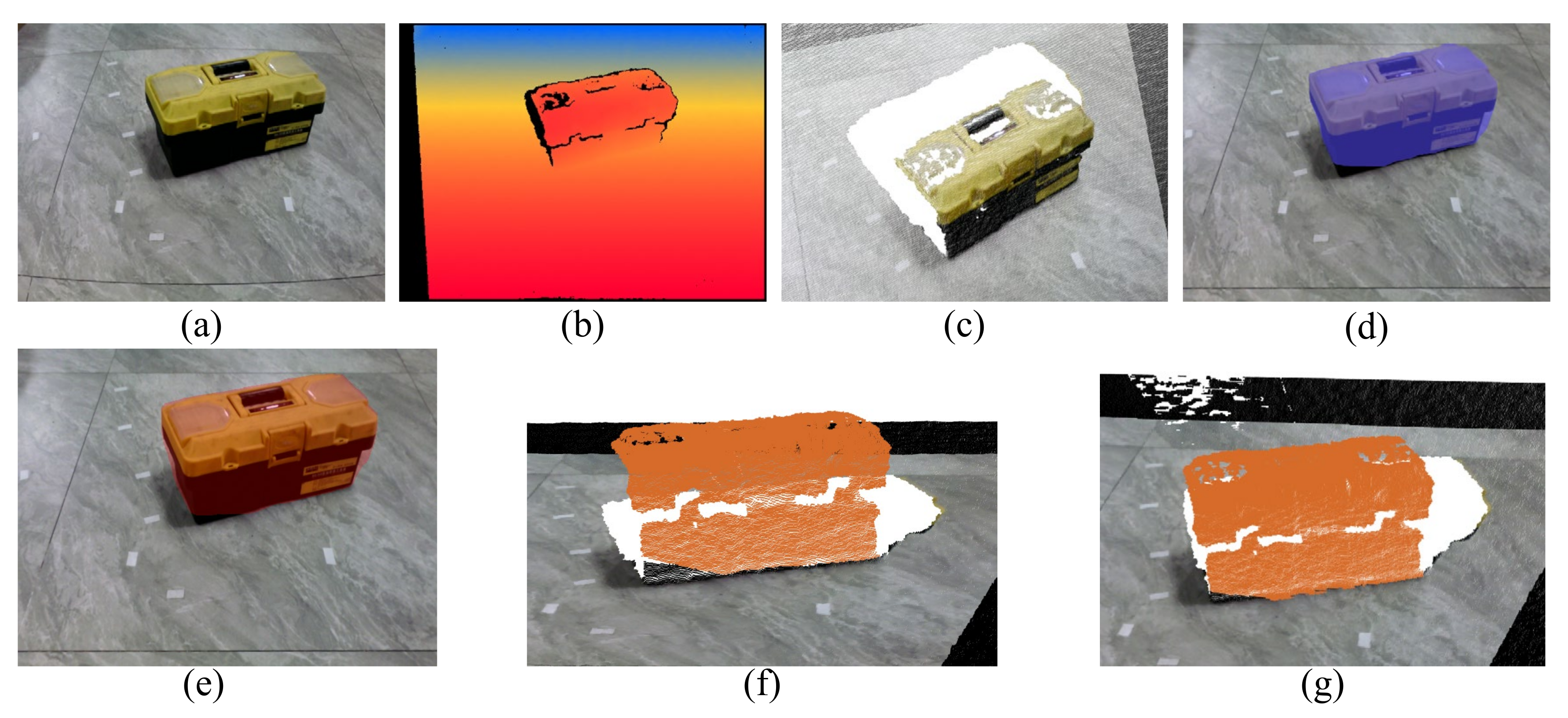
(1) The segmentation test is carried out on the independent object to segment the ground background and the target object. The results are shown in Figure 20.

Figure 20.
Independent object test results: (a) RGB image; (b) depth image; (c) point cloud; (d) segmentation effect of Mask-RCNN; (e) the improved segmentation effect; (f) segmentation effect of Mask-RCNN; (g) the improved point cloud segmentation effect.
Comparing Figure 20d and Figure 20e, it can be found that for a single object, the difference between Mask-RCNN and the improved results is not obvious. Because a single object without occlusion can get a good segmentation effect in Mask-RCNN, the improved result is only more accurate in detail and edge processing than before.
(2) The purpose of the segmentation test on different kinds of stacked objects is to separate the stacked objects, so as to further process the target object according to the application scenario. The results are shown in Figure 21.
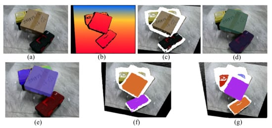
Figure 21.
Test results of stacked objects: (a) RGB image; (b) depth image; (c) point cloud; (d) segmentation effect of Mask-RCNN; (e) the improved segmentation effect; (f) segmentation effect of Mask-RCNN; (g) the improved point cloud segmentation effect.
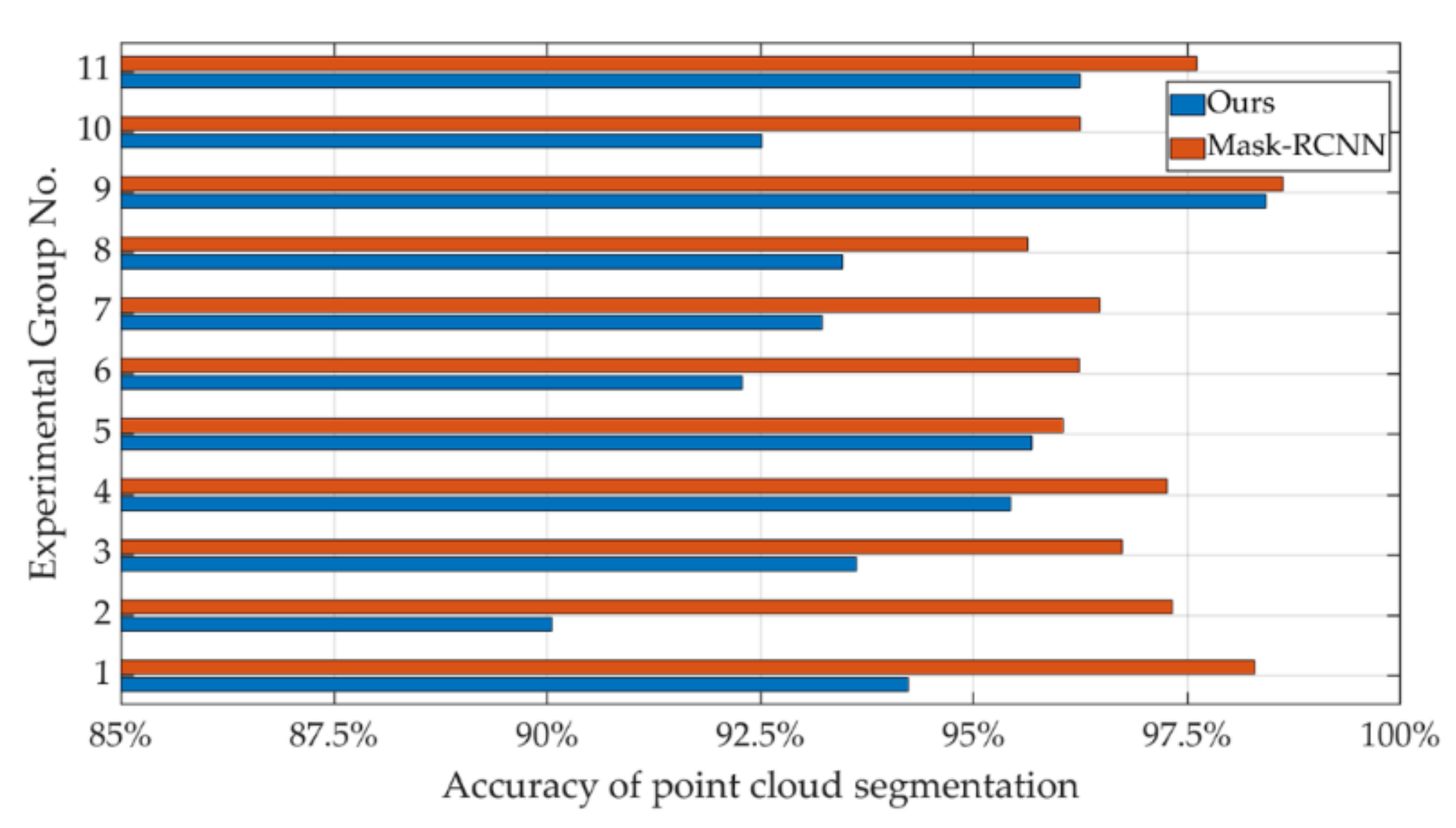
As shown in Table 2, they are the point cloud segmentation results of the above experiments. The accuracy results of multiple experiments with different objects are shown in Figure 22.
Table 2.
Experimental results of point cloud segmentation.
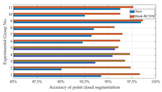
Figure 22.
Accuracy of segmentation of different objects.
The experimental results show that the improved Mask-RCNN in this paper has a significant improvement in the accuracy of point cloud segmentation, although it takes slightly more time than before. As shown in Figure 21f,g, the algorithm in this paper has a more obvious advantage in the segmentation of stacked objects.
4.4. Reconstruction and Positioning Accuracy Analysis
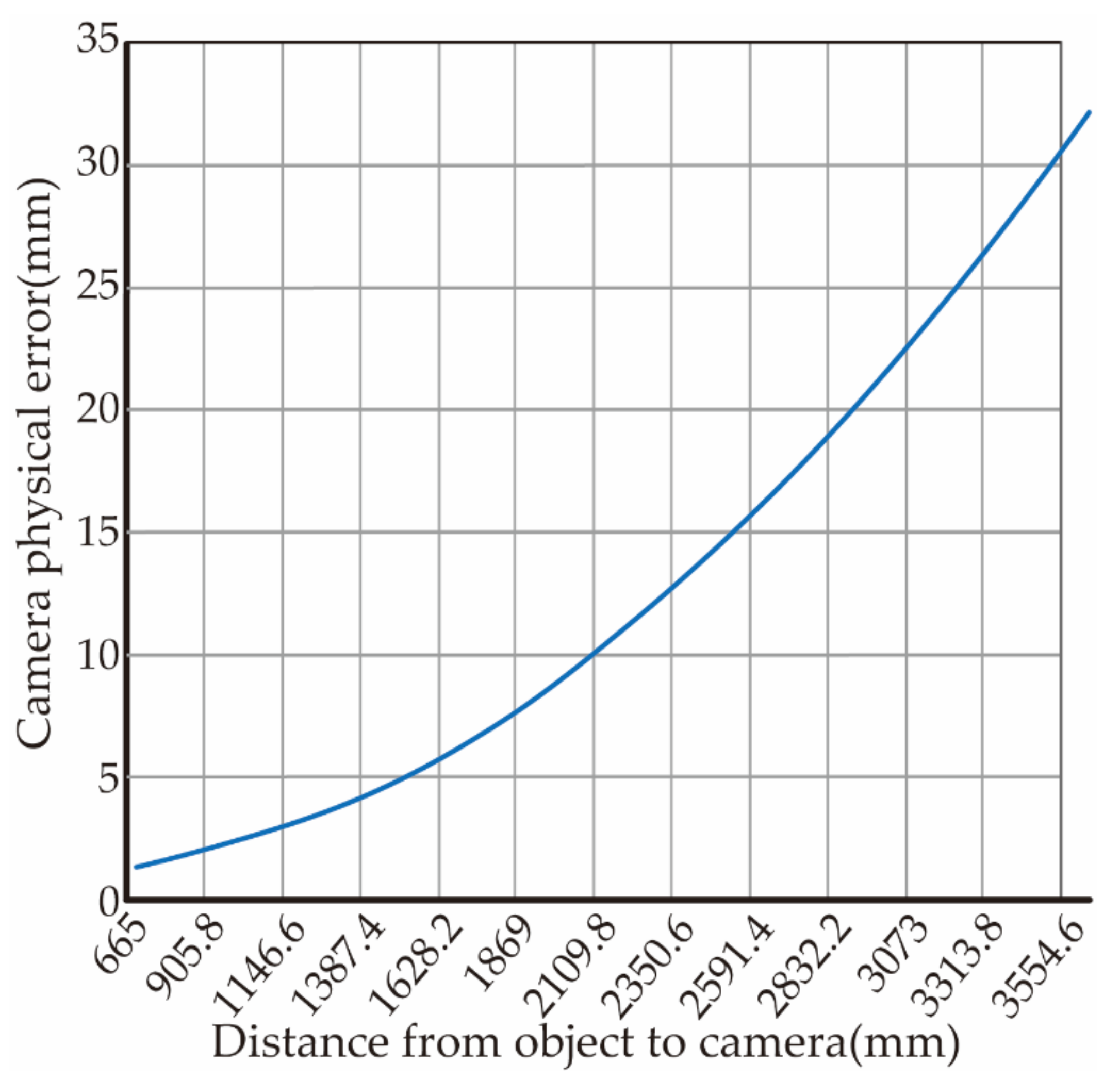
The measurement accuracy is measured and analyzed by the Euclidean distance between two points in space and the angle between the straight lines. During the experiment, 100 sets of image point data are randomly selected. Using the triangulation principle, the image data are reconstructed with spatial points according to the calibration result parameters of different image numbers. However, due to the limitation that the physical error of the RGB-D camera increases with the increase of the measured object distance (as shown in Figure 23). After eliminating the theoretical physical error, the root mean square error of the distance between two points in space and the angle between lines is calculated through all data, and the result is shown in Figure 24.
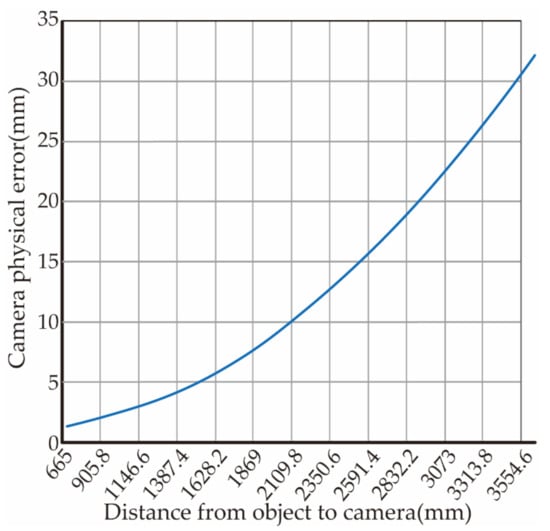
Figure 23.
RGB-D camera hardware errors (from RGB-D camera hardware for description).
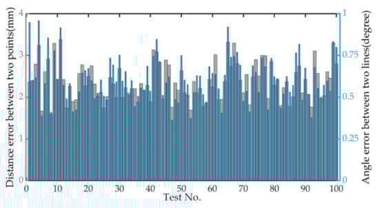
Figure 24.
Error map reconstruction.
The distance between the test object and the camera is about 1.3 m. It can be seen from Figure 23 that the physical error of the camera is about 3 mm. Therefore, the average reconstruction error of the actual algorithm in Figure 24 is 1.08 mm and the angle error is 0.61°, which can meet the requirements of visual reconstruction.
In order to test the positioning accuracy of the hand-eye system, we use a standard cube to extract the test points through the algorithm in this paper, and guide the manipulator end-effector to contact each test vertex respectively and calculate the linear distance between the test points (Table 3).
Table 3.
Positioning error.
Through the above tests, Figure 24 shows that the camera internal parameter calibration results adopted in this paper have certain stability in three-dimensional reconstruction. As shown in Table 3, the maximum error of the average error in each direction of the hand-eye system positioning is only 0.89% after excluding the camera hardware error. The reconstruction accuracy is less than 1.5 mm and the angle error is less than 1° after excluding the camera hardware error.
5. Discussion
5.1. Discussion of Calibration
As there is a certain coupling between the internal and external parameters during the calibration process, when the sampling point p is increased, it means that the constraints on the internal parameters are strengthened. The more p-values of the sampling points, the stronger the constraints on the parameters. This will reduce the coupling between the internal and external parameters, thus obtaining stable internal parameters.
For the experiment in this article, more than 23 images can make the calibration result stable. The effect of adding additional images on improving stability is no longer obvious. As shown in Figure 17, the integrated calibration error of the hand-eye system by the algorithm in this paper is less than 2 mm, which is close to the hardware accuracy of the camera sensor, when p = 23. Therefore, the selection of p = 23 can meet the actual calibration requirements.
This self-calibration method can complete the calibration of the internal and external parameters of the camera and the hand-eye matrix at one time. Compared with the eye-out-of-hand calibration method based on 3D printing ball [24], the self-calibration algorithm based on quaternion space curve path planning proposed in this paper can complete both internal and external parameter calibration of RGB-D camera and hand-eye calibration. Compared with the hand-eye calibration method based on three-dimensional reconstruction and line laser sensor [22], although the calibration accuracy in this paper cannot reach the method of [22], the calibration parts and equipment used in this paper can be easily obtained. The operation method is simpler and more suitable for the actual working environment.
5.2. Discussion of Registration and Reconstruction
As a classical method of point cloud coarse registration, PFH is too sensitive to the matching of point pairs as shown in Figure 18d. Due to the rapid fitting and early convergence of parts with very similar characteristics such as the ground, the detailed parts of the target object are not fully integrated and forms a certain angle dislocation. Accumulation of registration errors through three iterations leads to unsatisfactory results. 3Dsc uses logarithmic distance segmentation to make the shape context descriptor more sensitive to adjacent sampling points than far away points. Therefore, local features can be strengthened. As shown in Figure 18e, the algorithm has good registration results in the iterative registration process. However, due to the high computational time complexity, it is not suitable for the registration scene with strong real-time. NDT algorithm needs to divide the point cloud space into multiple cells, and its parameter setting is very important. Too big will result in low accuracy, too small will result in too high memory, thus only when the difference between the two images is small can it be matched accurately. As shown in Figure 18f, the performance of NDT is not ideal due to the large differences in the poses of complementary point clouds.
Generally, in the coarse registration stage, due to the controllable position and attitude of the camera in space, it has a good initial value when using ICP algorithm. This can greatly improve the accuracy and effectiveness of ICP algorithm. In the iterative process, compared with other coarse registration algorithms using point pair features, each registration is based on the results of the previous registration, thus it will gradually accumulate if there is an error. The registration accuracy of the coarse registration algorithm in this paper is not affected by the previous registration results, and the time-consuming is very low. It will not accumulate in the subsequent registration because of the large registration error in one time. Thereby this algorithm has great advantages in the eye-in-hand system. The above experiments also show that when the hardware acquisition accuracy of the point cloud acquisition device is much smaller than the positioning accuracy of the robotic arm, the desired results can be obtained without even using a precision registration algorithm such as the ICP algorithm.
The accuracy of point cloud reconstruction is obtained by the experiments in Section 4.4 of this paper. As shown in Table 2, the maximum error of the average error in each direction of the hand-eye system positioning is only 0.89% after excluding the camera hardware error. Therefore, the algorithm in this paper can give full play to the highest performance of the hardware equipment used in practical applications. If higher accuracy is needed, the equipment with better hardware accuracy can be chosen to cooperate with the algorithm in this paper.
5.3. Discussion of Registration and Reconstruction
As shown in Figure 21d,e, the improved Mask-RCNN cannot accurately extract and segment large-area occluded objects. However, because the depth image is more sensitive to the stereo contour, the improved algorithm can accurately recognize large-area occluded objects. The overall segmentation accuracy after the improvement is 3.1% higher than before, and the accuracy in individual cases is 8% higher than before.
From the above experimental results, it can be seen that the improved double pyramid feature fusion network model has stronger detail segmentation performance than Mask-RCNN in single object segmentation, especially in areas with obvious depth changes. For multi-object segmentation, Mask-RCNN cannot accurately generate mask for heavily occluded objects. The improved double pyramid feature fusion network is integrated into the depth image, which not only retains the color and edge sensitivity of Mask-RCNN, but also increases the sensitivity to depth change. Therefore, the occluded objects can still be segmented. However, in the case of too much occlusion, the phenomenon of dividing the same object into multiple objects (as shown in Figure 21g) needs to be further improved in the follow-up work.
6. Conclusions
In this paper, a fast self-calibration, point cloud reconstruction and segmentation method of RGB-D camera eye-in-hand system is proposed to quickly locate the target in space.
- (1)
- The algorithm in this paper is based on quaternion linear interpolation method for spatial spherical autonomous path planning. It can realize the self-calibration of the eye-on-hand system. The calibration of the RGB-D camera and the hand-eye calibration can be completed after the initial poses are set manually. During the self-calibration process, when the samples are 23, the calibration accuracy is close to the hardware accuracy of the camera sensor. The overall calibration time depends on the movement speed of the manipulator and the frame rate of the image acquisition device. The integrated error of hand-eye system positioning in each direction is less than 2 mm, which can reach the acquisition accuracy of the vision sensor. The algorithm in this paper has a certain speed, convenience and accuracy.
- (2)
- In the point cloud complementary image acquisition and point cloud registration reconstruction. The algorithm in this paper is based on the KD tree, that can accurately identify the missing pose of the point cloud hole. The holes in the point cloud are extracted to plan the shooting pose of the complementary image, and the target object is photographed from multiple symmetric angles. Combined with the iterative shooting pose of the manipulator, the rapid registration of the point cloud is realized, and the complete outer surface model of the target object is obtained. In terms of time and accuracy, it has greater advantages over traditional point-to-feature based algorithms, and only takes 0.602 s to complete the registration of a million-level point cloud. The accuracy of the reconstruction algorithm is less than 1.5 mm after eliminating the camera hardware error, and the angle error is less than 1°. The maximum average error of the hand-eye system positioning in each direction is only 0.89% after excluding the camera hardware error.
- (3)
- In point cloud segmentation, the improved double pyramid feature fusion Depth image is used to segment the RGB image through Mask R-CNN and mapped to the point cloud space, to achieve fast target segmentation of end-to-end 3D point cloud. The algorithm in this paper performs well in the segmentation of large-area occluded objects. Before the improvement, Mask-RCNN cannot accurately extract and segment large-area occluded objects, but the improved algorithm can accurately identify large-area occluded objects. Under multi-object stacking, the algorithm in this paper is obviously better than before. The overall segmentation accuracy improved by 3.1% over the pre-improvement, and that in the stacked case improved by 8% over the pre-improvement.
However, the self-calibration algorithm in this paper is limited to the eye-in-hand system, and further research is needed to extend it to the eye-out-of-hand system and mobile robots. In the results of point cloud segmentation, although the algorithm can segment large-area occluded objects, the discontinuity of point cloud caused by occlusion makes the algorithm recognize it as two objects, which also needs to be further improved in the follow-up work.
Author Contributions
Conceptualization, X.Y. and Y.T.; Methodology, X.Y. and Y.T; Software, Y.T.; Validation, Y.T., Q.C. and D.Z.; Formal Analysis, X.H.; Investigation, X.H.; Resources, X.H. and Y.T.; Data Curation, Q.C.; Writing—Original Draft Preparation, Y.T.; Writing—Review and Editing, Y.T.; Visualization, X.Y. and Y.T.; Supervision, X.H. and D.Z.; Project Administration, D.Z.; Funding Acquisition, X.H. and D.Z. All authors have read and agreed to the published version of the manuscript.
Funding
This work is supported by the National Natural Science Foundation of China (No. 52075152, No. 61976083). Supported by the Collaborative Innovation Center of Intelligent Green Manufacturing Technology and Equipment, Shandong (IGSD-2020-006).
Institutional Review Board Statement
Not applicable.
Informed Consent Statement
Not applicable.
Data Availability Statement
The data sets used and/or analyzed during the current study are available from the corresponding author upon reasonable request.
Acknowledgments
We are grateful to Hubei University of Technology and Qingdao University of Science and Technology for creating good experimental conditions for us. We would like to thank Collaborative Innovation Center of Intelligent Green Manufacturing Technology and Equipment for the open fund support (IGSD-2020-006). We are grateful to the National Natural Science Foundation of China for the grant support (No. 52075152, No. 61976083).
Conflicts of Interest
The authors declare no conflict of interest.
References
- Tipary, B.; Erdős, G. Generic development methodology for flexible robotic pick-and-place workcells based on Digital Twin. Robot. Comput.-Integr. Manuf. 2021, 71, 102140. [Google Scholar] [CrossRef]
- Zhao, X.; Tao, B.; Han, S.; Ding, H. Accuracy analysis in mobile robot machining of large-scale workpiece. Robot. Comput.-Integr. Manuf. 2021, 71, 102153. [Google Scholar] [CrossRef]
- Kana, S.; Lakshminarayanan, S.; Mohan, D.M.; Campolo, D. Impedance controlled human–robot collaborative tooling for edge chamfering and polishing applications. Robot. Comput.-Integr. Manuf. 2021, 72, 102199. [Google Scholar] [CrossRef]
- Mayetin, U.; Kucuk, S. A low cost 3-DOF force sensing unit design for wrist rehabilitation robots. Mechatronics 2021, 78, 102623. [Google Scholar] [CrossRef]
- Zhang, Z. Flexible camera calibration by viewing a plane from unknown orientations. In Proceedings of the Seventh IEEE International Conference on Computer Vision, Kerkyra, Greece, 20–27 September 1999; Volume 1, pp. 666–673. [Google Scholar]
- Peters, A.; Schmidt, A.; Knoll, A. Extrinsic Calibration of an Eye-In-Hand 2d Lidar Sensor in Unstructured Environments Using ICP. IEEE Robot. Autom. Lett. 2020, 5, 929–936. [Google Scholar] [CrossRef] [Green Version]
- Li, M.; Du, Z.; Ma, X.; Dong, W.; Gao, Y. A robot hand-eye calibration method of line laser sensor based on 3D reconstruction. Robot. Comput.-Integr. Manuf. 2021, 71, 102136. [Google Scholar] [CrossRef]
- Torres-Jara, E.; Natale, L. Sensitive manipulation: Manipulation through tactile feedback. Int. J. Hum. Robot. 2018, 15, 1850012. [Google Scholar] [CrossRef] [Green Version]
- Xue, B.; Chang, B.; Peng, G.; Gao, Y.; Tian, Z.; Du, D.; Wang, G. A vision based detection method for narrow butt joints and a robotic seam tracking system. Sensors 2019, 19, 1144. [Google Scholar] [CrossRef] [Green Version]
- Zhou, Q.Y.; Park, J.; Koltun, V. Fast Global Registration. In European Conference on Computer Vision; Springer: Berlin/Heidelberg, Germany, 2016. [Google Scholar] [CrossRef]
- Sinha, A.; Bai, J.; Ramani, K. Deep Learning 3D Shape Surfaces Using Geometry Images. In Proceedings of the European Conference on Computer Vision, Amsterdam, The Netherlands, 8–16 October 2016; pp. 223–240. [Google Scholar]
- Zeng, A.; Song, S.; Niener, M.; Fisher, M.; Xiao, J.; Funkhouser, T. 3DMatch: Learning Local Geometric Descriptors from RGB-D Reconstructions. Comput. Vis. Pattern Recognit. 2016, 1, 199–208. [Google Scholar]
- Zhao, B.; Hua, X.; Yu, K.; Xuan, W.; Chen, X.; Tao, W. Indoor Point Cloud Segmentation Using Iterative Gaussian Mapping and Improved Model Fitting. IEEE Trans. Geosci. Remote Sens. 2020, 58, 7890–7907. [Google Scholar] [CrossRef]
- Awwad, T.M.; Zhu, Q.; Du, Z.; Zhang, Y. An improved segmentation approach for planar surfaces from unstructured 3D point clouds. Photogramm. Rec. 2010, 25, 5–23. [Google Scholar] [CrossRef]
- Maturana, D.; Scherer, S. VoxNet: A 3D Convolutional Neural Network for real-time object recognition. In Proceedings of the 2015 IEEE/RSJ International Conference on Intelligent Robots and Systems (IROS), Hamburg, Germany, 28 September–3 October 2015. [Google Scholar]
- He, K.; Gkioxari, G.; Dollár, P.; Girshick, R. Mask r-cnn. In Proceedings of the IEEE International Conference on Computer Vision, Venice, Italy, 22–29 October 2017; pp. 2961–2969. [Google Scholar]
- De Oca, A.M.; Flores, G. The AgriQ: A low-cost unmanned aerial system for precision agriculture. Expert Syst. Appl. 2021, 182, 115163. [Google Scholar] [CrossRef]
- Smisek, J.; Jancosek, M.; Pajdla, T. 3D with Kinect. In Consumer Depth Cameras for Computer Vision; Springer: London, UK, 2013; pp. 3–25. [Google Scholar]
- Zhang, Y.; Funkhouser, T. Deep depth completion of a single rgb-d image. In Proceedings of the IEEE Conference on Computer Vision and Pattern Recognition, Salt Lake City, UT, USA, 18–22 June 2018; pp. 175–185. [Google Scholar]
- Tsai, R.Y.; Lenz, R.K. A new technique for fully autonomous and efficient 3 D robotics hand/eye calibration. IEEE Trans. Robot. Autom. 1989, 5, 345–358. [Google Scholar] [CrossRef] [Green Version]
- Fassi, I.; Legnani, G. Hand to sensor calibration: A geometrical interpretation of the matrix equation AX = XB. J. Robot. Syst. 2005, 22, 497–506. [Google Scholar] [CrossRef]
- Nie, E.; Li, J.; Zhang, R.; Cao, L.; Sun, L.; Liu, H. Three dimensional point cloud hole repairing strategy for binocular stereo reconstruction. In Proceedings of the 2017 IEEE International Conference on Robotics and Biomimetics (ROBIO), Macao, China, 5–8 December 2017; pp. 2456–2461. [Google Scholar]
- Rusu, R.B.; Blodow, N.; Marton, Z.C.; Beetz, M. Aligning point cloud views using persistent feature histograms. In Proceedings of the 2008 IEEE/RSJ International Conference on Intelligent Robots and Systems, Nice, France, 22–26 September 2008; pp. 3384–3391. [Google Scholar]
- Rusu, R.B.; Blodow, N.; Beetz, M. Fast point feature histograms (FPFH) for 3D registration. In Proceedings of the 2009 IEEE International Conference on Robotics and Automation, Kobe, Japan, 12–17 May 2009; pp. 3212–3217. [Google Scholar]
- Frome, A.; Huber, D.; Kolluri, R.; Bülow, T.; Malik, J. Recognizing objects in range data using regional point descriptors. In Proceedings of the European Conference on Computer Vision, Prague, Czech Republic, 11–14 May 2004; Springer: Berlin, Germany, 2004; pp. 224–237. [Google Scholar]
- Biber, P.; Straßer, W. The normal distributions transform: A new approach to laser scan matching. In Proceedings of the Proceedings 2003 IEEE/RSJ International Conference on Intelligent Robots and Systems (IROS 2003) (Cat. No. 03CH37453), Las Vegas, NV, USA, 27–31 October 2003; Volume 3, pp. 2743–2748. [Google Scholar]
- Chetverikov, D.; Svirko, D.; Stepanov, D.; Krsek, P. The trimmed iterative closest point algorithm. In Proceedings of the Object Recognition Supported by User Interaction for Service Robots, Quebec City, QC, Canada, 11–15 August 2002; Volume 3, pp. 545–548. [Google Scholar]
- Fitzgibbon, A.W. Robust registration of 2D and 3D point sets. Image Vis. Comput. 2003, 21, 1145–1153. [Google Scholar] [CrossRef]
- Serafin, J.; Grisetti, G. NICP: Dense Normal Based Point Cloud Registration. In Proceedings of the 2015 IEEE/RSJ International Conference on Intelligent Robots and Systems (IROS), Hamburg, Germany, 28 September–2 October 2015. [Google Scholar] [CrossRef] [Green Version]
- Thirion, J.P. The extremal mesh and the understanding of 3D surfaces. Int. J. Comput. Vis. 1996, 19, 115–128. [Google Scholar] [CrossRef]
- Aiger, D.; Kedem, K. Approximate input sensitive algorithms for point pattern matching. Pattern Recognit. 2010, 43, 153–159. [Google Scholar] [CrossRef]
- Mellado, N.; Aiger, D.; Mitra, N.J. Super 4pcs fast global pointcloud registration via smart indexing. In Computer Graphics Forum; Wiley Online Library: Hoboken, NJ, USA, 2014; Volume 33, pp. 205–215. 4p. [Google Scholar]
- Lim, S. Parameter analysis in Fast Global Registration to improve accuracy and speed. J. Korea Inst. Inf. Commun. Eng. 2021, 25, 799–806. [Google Scholar]
- Li, C.; Shi, H.; Li, Z. Point Cloud Registration Method Based on Combination of Convolutional Neural Network and Improved Harris-SIFT. Laser Optoelectron. Prog. 2020, 57, 201102. [Google Scholar]
- Wang, Y.; Shi, H. A Segmentation Method for Point Cloud Based on Local Sample and Statistic Inference. Commun. Comput. Inf. Sci. 2015, 482, 274–282. [Google Scholar]
- Kalogerakis, E.; Averkiou, M.; Maji, S.; Chaudhuri, S. 3D shape segmentation with projective convolutional networks. In Proceedings of the Proceedings of the IEEE Conference on Computer Vision and Pattern Recognition, Honolulu, HI, USA, 21–26 July 2017; pp. 3779–3788. [Google Scholar]
- Su, H.; Maji, S.; Kalogerakis, E.; Learned-Miller, E. Multi-view convolutional neural networks for 3d shape recognition. In Proceedings of the IEEE International Conference on Computer Vision, Santiago, Chile, 11–17 October 2015; pp. 945–953. [Google Scholar]
- Feng, Y.; Zhang, Z.; Zhao, X.; Ji, R.; Gao, Y. GVCNN: Group-view convolutional neural networks for 3D shape recognition. In Proceedings of the IEEE Conference on Computer Vision and Pattern Recognition, Salt Lake City, UT, USA, 18–22 June 2018; pp. 264–272. [Google Scholar]
- Kang, C.G. Online trajectory planning for a PUMA robot. Int. J. Precis. Eng. Manuf. 2007, 8, 16–21. [Google Scholar]
- Jiang, X.; Barnett, E.; Gosselin, C. Dynamic Point-to-Point Trajectory Planning Beyond the Static Workspace for Six-DOF Cable-Suspended Parallel Robots. In IEEE Transactions on Robotics; IEEE: Piscataway, NJ, USA, 2018; Volume 34, pp. 781–793. [Google Scholar]
- Lin, T.Y.; Dollár, P.; Girshick, R.; He, K.; Hariharan, B.; Belongie, S. Feature pyramid networks for object detection. In Proceedings of the IEEE Conference on Computer Vision and Pattern Recognition, Honolulu, HI, USA, 21–26 July 2017; pp. 2117–2125. [Google Scholar]
- Zhai, S.; Shang, D.; Wang, S.; Dong, S. DF-SSD: An improved SSD object detection algorithm based on DenseNet and feature fusion. IEEE Access 2020, 8, 24344–24357. [Google Scholar] [CrossRef]


Publisher’s Note: MDPI stays neutral with regard to jurisdictional claims in published maps and institutional affiliations. |
© 2021 by the authors. Licensee MDPI, Basel, Switzerland. This article is an open access article distributed under the terms and conditions of the Creative Commons Attribution (CC BY) license (https://creativecommons.org/licenses/by/4.0/).