Article

Analysis and Suppression of the Eddy Current Damping Force of the Cooling Plate of a Permanent Magnet Linear Motor

School of Electrical Engineering and Automation, Harbin Institute of Technology, Harbin 150000, China
*
Author to whom correspondence should be addressed.
Symmetry 2021, 13(11), 2025; https://doi.org/10.3390/sym13112025
Submission received: 13 September 2021 / Revised: 13 October 2021 / Accepted: 20 October 2021 / Published: 26 October 2021
(This article belongs to the Section Computer)

Abstract

:
This paper proposes a new symmetrical cooling plate. It can significantly reduce the eddy current damping force of the water-cooled metal plate. To increase the thrust density of coreless permanent magnet linear motors, cooling plates must be placed on the armature surface to reduce the temperature rise that is caused by high electrical density. However, when the motor moves at a high speed, extra damping force will be generated in the cooling plate, which affects the thrust quality and precision of the permanent magnet linear motor. In this study, we elaborate the mechanism of damping force generation in the cooling plate and propose a new symmetrical cooling plate with low damping force. This paper introduces the topology of a linear motor cooling system and presents an analytical model of the eddy current distribution of a water-cooled plate. The surface current equivalence method is used to calculate the magnitude of the damping force. A new, symmetrical water-cooled plate design method is proposed. This method uses the eddy current vector synthesis principle to cancel the eddy currents that are generated in each region, and to reduce the damping force that is generated in the cooling plate during motor motion. Finally, a 3D simulation model of the motor system is established and an experimental platform is built. The correctness of the analytical model and the effectiveness of the cooling plate design are verified using a simulation and an experiment.

1. Introduction

Linear motors are widely used in machine tool processing because they can directly drive a load in a linear motion. In precision manufacturing, there are stricter demands for linear motors, such as those regarding thrust density and thrust fluctuation. Besides structural improvements, increasing the armature density of the motor is the most effective way to increase the thrust density [1,2,3,4,5]. However, the temperature rise that is caused by the excessive electrical density is also an unacceptable problem in the precision field [6,7]. Therefore, water-cooled plates are installed on the armature surface to improve heat dissipation [8,9]. This is also a widely used, and strongly effective, method of forced cooling [10]. However, due to the conductivity of the cooling plate, the relative motion of the permanent magnet and the metal cooling plate during the operation of the motor causes eddy currents in the water-cooled plate. These ring currents are termed motional eddy currents [11,12]. These eddy currents generate a magnetic field that prevents the external magnetic field from changing, thus creating a damping force that affects the motion of the mover. For motor yoke, silicon steel sheets can be used to isolate the eddy circuit and suppress the eddy effect. However, water-cooled plates have internal water channels and are fed with coolant. Hence, eddy currents cannot be suppressed by isolating the electrical circuit. Therefore, it is important to optimize the structure of the cooling plate.
Domestic and foreign scholars have conducted studies focusing on suppressing damping forces based on the cooling structure of linear motors. Professor Baoquan Kou developed a model for calculating the damping force of a conductor plate, which can control the damping force by adjusting the size of the metal plate, according to the analytical formula [13]. Yinxi Jin proposed an analytical model that considers the transverse edge effect for bilateral-type permanent magnet linear motors. It further optimizes the previous damping force calculation model and improves calculation accuracy [14]. Babak Ebrahimi proposed an analytical model of eddy current damping force and a method of achieving a higher damping force. [15,16]. A patent that was filed by the Dutch company, ASML, suggested improving the cooling plate to suppress the damping force by increasing the resistance of the eddy current path [17]. Based on this, Donghua Pan designed a new cooling plate structure, using the principle of reversing the electromotive force. However, the suppression effect is not suitable for a long-stator linear motor, because the application object is the voice coil motor, which does not contain the cross-pole-induced eddy currents that are caused by the motion of the magnetic poles [18]. In addition, many scholars have proposed many methods in suppressing motor eddy currents. Zoubida Belli used a combination of finite element calculation tools and genetic algorithms to solve and suppress eddy currents in the motor [19]. Jasmin Smajic used a multiobjective optimization method to identify the optimal structural dimensions and to optimize the eddy currents’ shielding of the device [20].
The structure of this paper is as follows: Section 2 introduces the topology of the motor under study. Section 3 establishes a two-dimensional analytical model (with five regions) for the damping force, and obtains the expressions of the damping force of the cooling system. Then, two novel cooling plates are proposed, which can significantly reduce the damping force by using the principle of eddy current vector synthesis. Finally, a 3D simulation model is established. The simulation results verified the accuracy of the calculated model. Experiments confirm the new cooling plate scheme is more effective in suppressing the damping force.

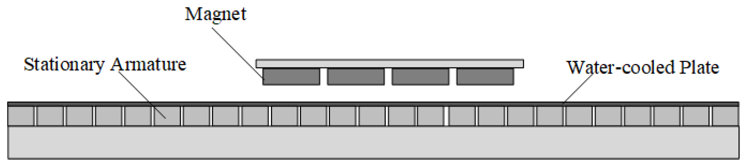
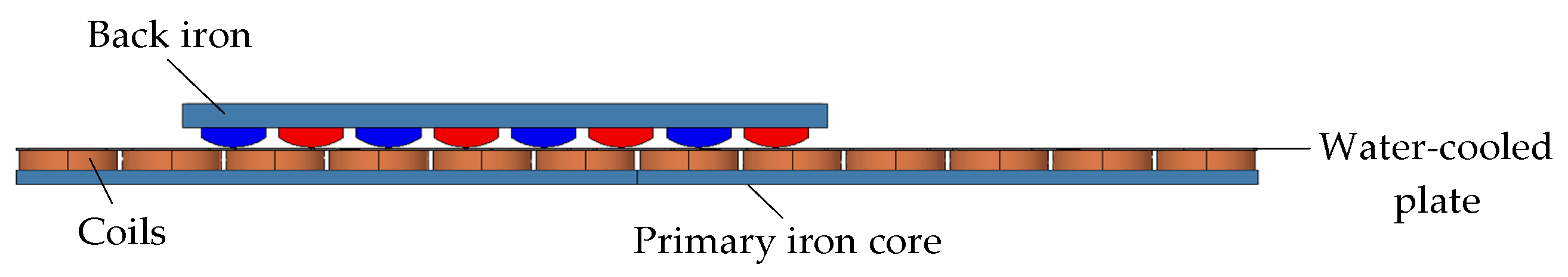
2. Single-Sided-Type Permanent Magnet Synchronous Linear Motor Structure

Figure 1 shows the topology of a single-sided-type permanent magnet synchronous linear motor (PMLSM). The experimental platform used in this paper is a moving-magnet linear motor, and the dimensional parameters of the motor are shown in Table 1. The motor armature is fixed on the mounting bracket. The cooling plate covers the surface of the armature to occupy the air gap, so the thickness of the water-cooled plate cannot be chosen arbitrarily. To study the effect of the thickness of the cooling plate on the damping force, two thicknesses of 1 mm and 3 mm were selected as the objects of this paper.

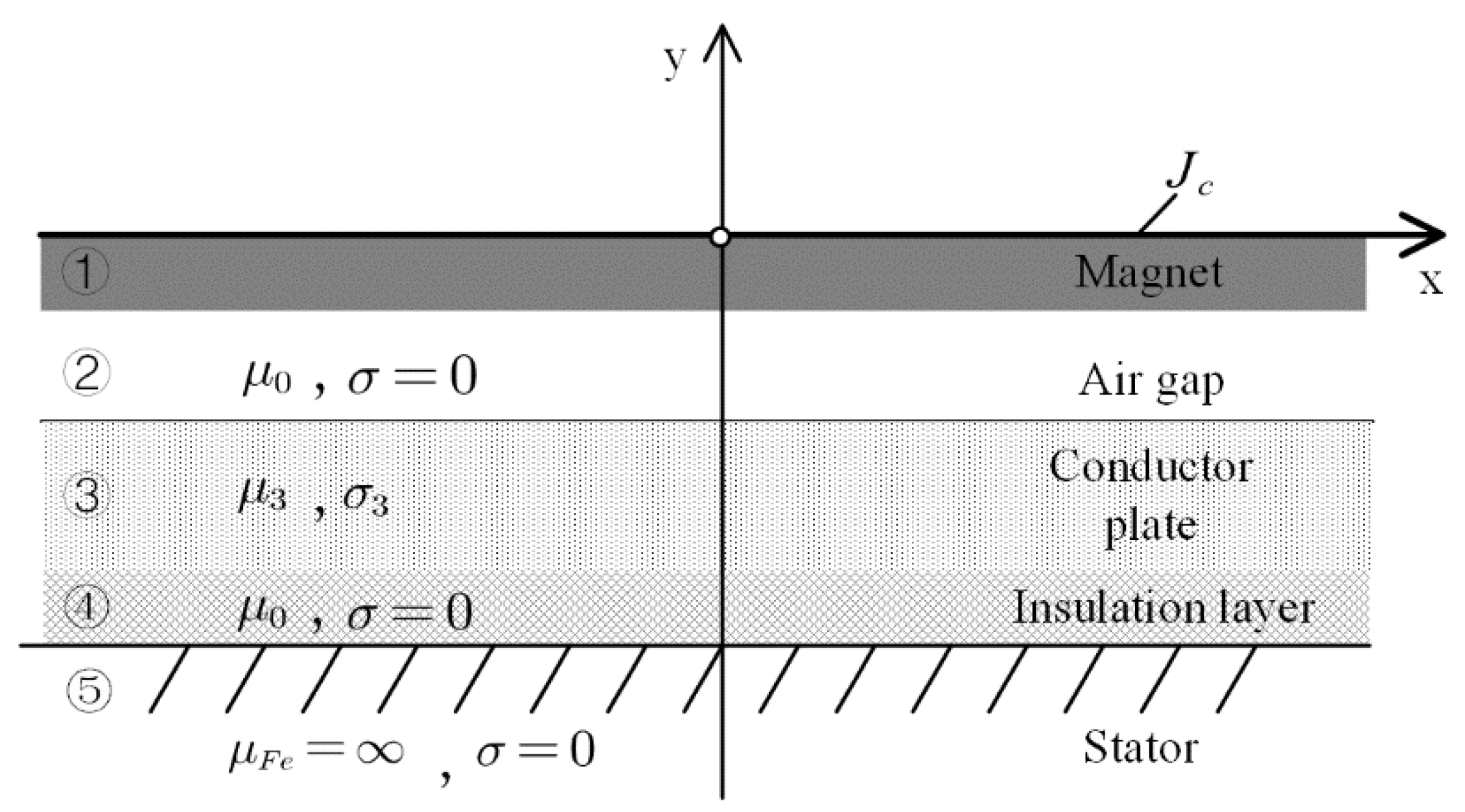
3. Cooling Plate Eddy Current Damping Force Calculation

In this section, Figure 2 shows a damping force calculation model [21]. Since the air gap magnetic field is mainly generated by the permanent magnets, the eddy current that is caused by the armature can be neglected.
Figure 2 shows a two-dimensional model with five regions:
(1)
Region 1: permanent magnets, which are the source of the magnetic density that generates the air gap magnetic field;
(2)
Region 2: air gap;
(3)
Region 3: the water-cooled plate, which causes eddy currents in this area, is the main area analyzed in this section;
(4)
Region 4: insulation paint layer;
(5)
Region 5: primary winding and core.
Before the analysis, several assumptions were made, as follows:
Assumption 1.
The primary core, conductor plate and back iron are considered to be infinitely wide in the x-direction. Ignoring the effect that is caused by the finite length of the secondary linear motor, it can be assumed that there is no distortion of the magnetic field in the x-direction.
Assumption 2.
We only considered the magnetic density change in the y-direction that is caused by the relative motion between the permanent magnet and the cooling plate. The density of the eddy current that is caused in the conductor plate appears in the z-axis direction, and this paper does not consider the influence of saturation.
Assumption 3.
The permanent magnets were replaced with infinitely long surface currents. These current sheets were fed with sinusoidal traveling wave currents. The equivalence principle of the current layers is that the magnetic density that is produced by the surface currents is equal to the magnetic density that is produced by the permanent magnets. In addition, since the object of the study is a slotless motor with a uniform motor air gap length, Carter’s coefficient is not used in the calculation.
According to Assumption (3), the surface current of infinite length can be expressed as [22]:
J c = n = 1 J n cos ( k x )
Since J c is in the z-direction, the vector magnetic potential is also in the z-direction of each region.
{ A ( x , y , t ) = k A z A z = A z ( y ) cos ( k x φ ) = Re [ A ˙ z e j ( k x ) ]
In region 2, the conductivity σ 2 = 0 , and the magnetic potential A ˙ z 2 satisfies the Laplace equation:
2 A ˙ z 2 x 2 + 2 A ˙ z 2 y 2 = 0
In the sinusoidal steady state case, t = j ω and x = j π τ , meaning that Equation (3) can be rewritten as:
2 A ˙ z 2 y 2 ( π τ ) 2 A ˙ z 2 = 0
The solution can be obtained as:
A ˙ z 2 = C 2 sh π τ y + D 2 ch π τ y
In region 3, the conductivity is zero, and A ˙ z 3 satisfies the two-dimensional eddy current equation:
2 A ˙ z 3 x 2 + 2 A ˙ z 3 y 2 = j ω μ σ A ˙ z 3
Similarly, the solution can be obtained as:
A ˙ z 3 = C 3 sh β y + D 3 ch β y
where β = ( π τ ) 2 + j ω μ σ .
In region 4, the magnetic potential A ˙ z 4 satisfies the Laplace equation:
2 A ˙ z 4 x 2 + 2 A ˙ z 4 y 2 = 0
The solution is:
A ˙ z 4 = C 4 e π τ y + D 4 e π τ y
The magnetic potential satisfies the following boundary conditions:
Between region 1 and region 2:
H ˙ x 2 ( y = 0 ) = 1 μ 0 A ˙ x 2 y ( y = 0 ) = J n
Between region 2 and region 3:
{ A ˙ z 2 = A ˙ z 3 1 μ 0 A ˙ z 2 y = 1 μ 3 A ˙ z 3 y
Between region 3 and region 4:
{ A ˙ z 3 = A ˙ z 4 1 μ 3 A ˙ z 3 y = 1 μ 0 A ˙ z 4 y
where μ 0 is the air permeability, μ 3 is the conductor plate permeability and μ F e is the yoke permeability. Meanwhile, when y , A ˙ z 4 is limited. Thus, D 4 = 0 .
C 3 = μ 0 J π τ ch π τ δ ch β δ · ( 1 γ th ( β + δ ) ) · ( [ 1 γ th β ( d + δ ) ] ( γ th π τ δ th β δ ) + [ γ th β ( d + δ ) ] ( γ β δ th π τ δ ) ) 1
D 3 = μ 0 J π τ ch π τ δ ch β δ · ( γ th ( β + δ ) ) · ( [ 1 γ th ( β + δ ) ] ( γ th π τ δ th β δ ) + [ γ th β ( d + δ ) ] ( γ β δ th π τ δ ) ) 1
where J = n = 1 J n .
Therefore, the current density and magnetic field intensity in the conductor plate can be obtained as:
B y 3 = A ˙ z 3 x = j π τ ( C 3 sh β y + D 3 ch β y )
J z 3 = σ ( v · B y 3 )
Furthermore, the expression for the damping force can be obtained as:
F = V J z 3 × B y 3 d V

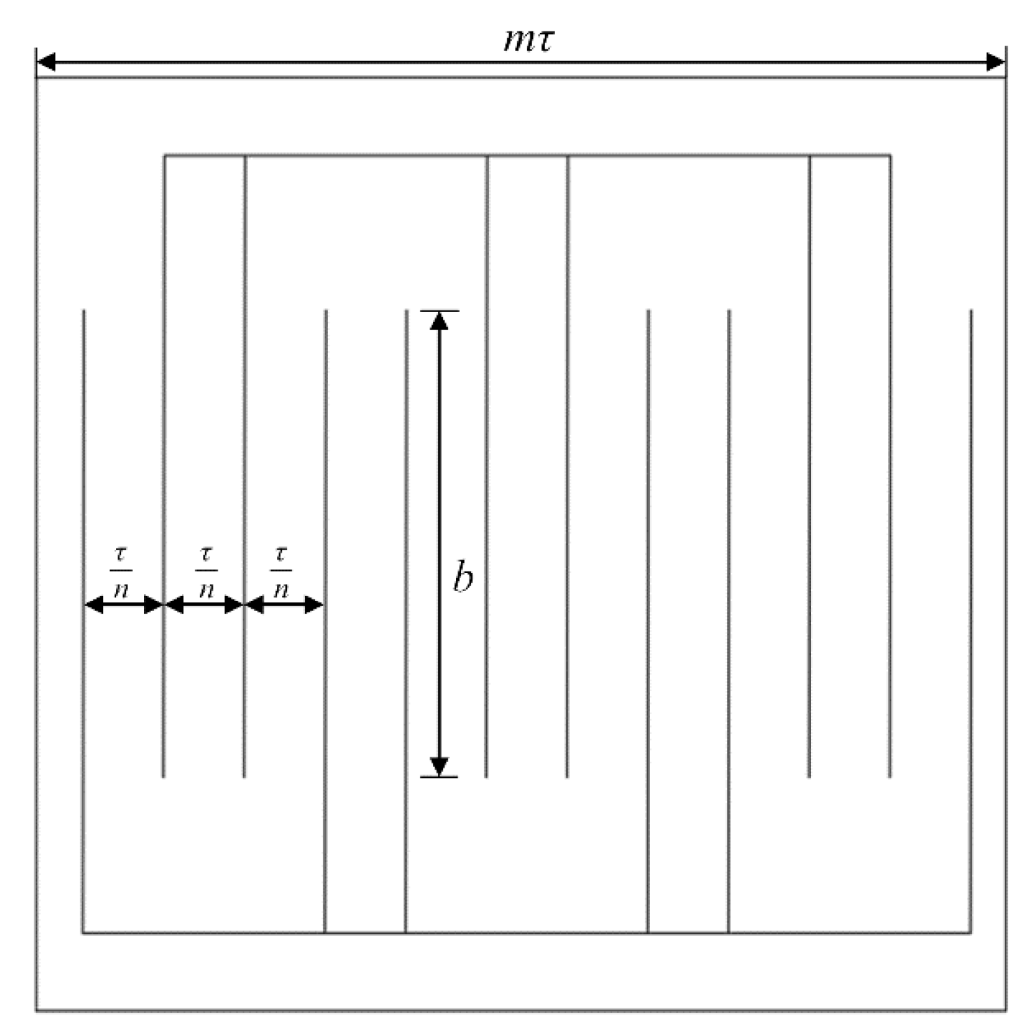
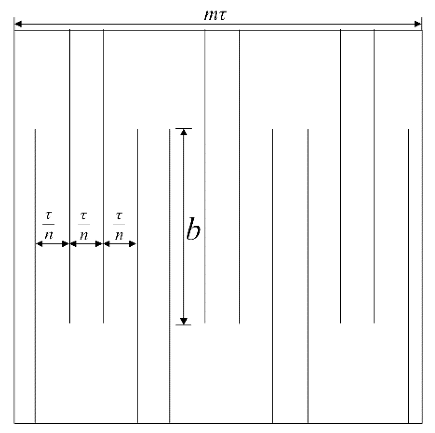
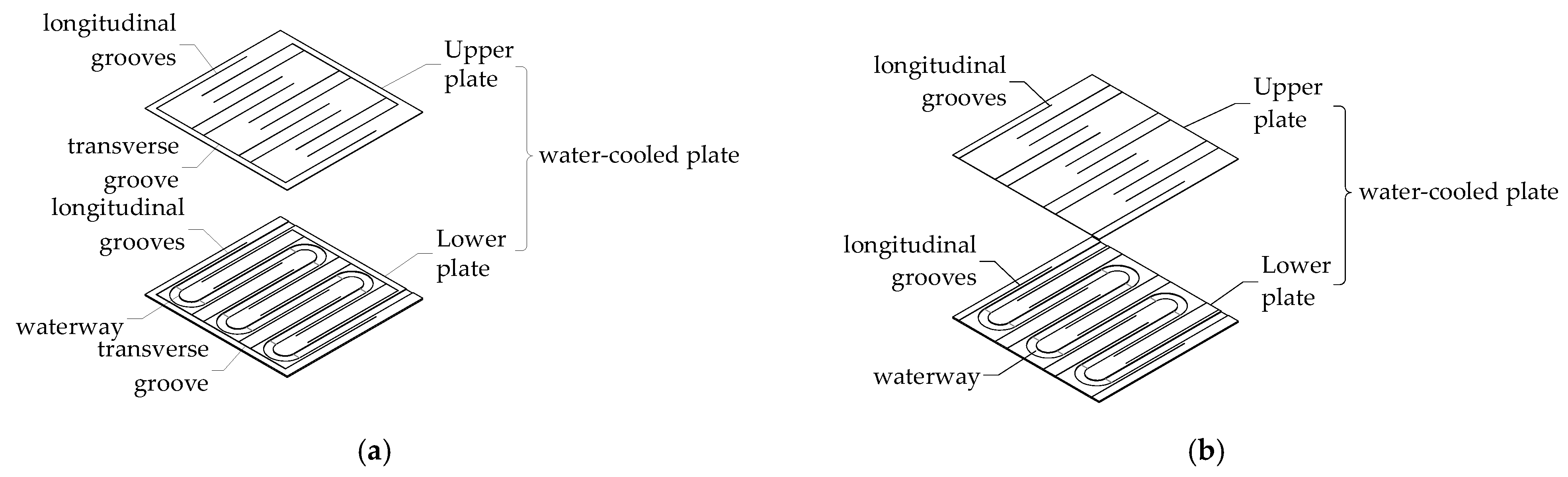
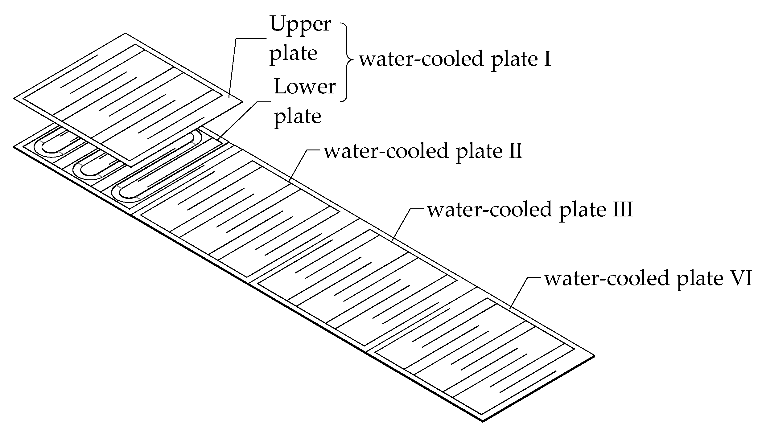
4. New Cooling Plate Design Method

The magnetic field intensity, eddy current electric density and the damping force on the cooling plate were obtained by using the analytical calculations shown in the previous section. This section will introduce a new cooling plate to reduce the eddy damping force of a water cooling system.
In general, a conventional water-cooled plate is a complete plate covering the surface of the armature. However, for long-stator, moving-magnet-type linear motors, this water-cooled structure has many problems. First, the waterway of an entire water-cooled plate is overly long. Hence, there is a loss of water flow speed near the outlet when there is only one inlet, which reduces the cooling effect. Moreover, the water temperature rises when it flows through an entire water-cooled plate, and the cooling effect of the water-cooled system decreases when the water temperature increases, which eventually results in an uneven cooling effect.
A symmetrical, segmented, water-cooled system is designed to address the above problems. First, the cooling system is divided into multiple cooling panels of length m τ . m is an integer. m represents the length of a single section of the segmented cooling plate. The selection of m requires a consideration of the motor stroke and waterway length. The length of each waterway is reduced. Furthermore, in order to reduce the damping force of the cooling system, each section of the water-cooled plate must be optimized. Here, laser cutting can be used in the area that is covered by the magnetic poles at intervals of τ / n , where the cutting length is equal to the length of the poles. n is an integer. n describes the sparsity of the cut on a single segment of the plate. n has a large value if better eddy current damping force suppression is required, and a small value if a wider waterway is required. When i is an odd number, the 2ith and 2i + 1st longitudinal grooves on each cooling plate are connected on one side by a transverse groove; similarly, when i is an even number, the 2ith and 2i + 1st longitudinal grooves on each cooling plate are connected on the other side by the other transverse groove, as shown in Figure 3. In this paper, m = 4, n = 3.
In this way, the eddy current can be connected to a loop, while the expression for the eddy current density that is generated in the kth region is:
J k = σ · v · B f sin ( π τ x π k n ) cos ( π v τ t )
As a result, in the divided eddy current loop, the vector sum of the eddy currents that are induced in each region is:
J = σ · v · B f k = 1 n m sin ( π τ x π k n ) cos ( π v τ t ) = 0
The final effect is to eliminate the damping force.
In addition, another design of the structure is to use the water-cooled plate boundary as a transverse groove, as shown in Figure 4. Since novel structure II replaces the transverse grooves with boundaries, the coverage of the waterway can be further increased without being constrained by the transverse grooves. Therefore, novel structure II should be chosen for applications where there is a limitation in size. Both cutting forms have the same effect of reducing the damping force. However, the former cutting method requires transverse cutting, and the process is more complex. A plate that is processed in the latter way has less strength when the plate is thinner, due to the cutting of the ends. Therefore, novel structure I should be selected under the requirements of high flatness and strength of the cooling plate.
The structural schematic of the two novel structures is shown in Figure 5. The cooling plate is divided into two parts: the upper plate and the lower plate. The process grooves in the lower plate act as water channels. As can be seen in the figure, the water channels are distributed between two adjacent cut lines. n is used to affect the width of the water channels. However, the area of the waterway is not affected. The larger the value of n, the finer the waterway, but the more densely distributed the waterway is. Similarly, the smaller the value of n, the wider the waterway, but the more sparsely distributed the waterway is. Therefore, the heat dissipation capacity of the novel structure is not reduced, compared to the traditional structure. The installation schematic of the segmented cooling plate is shown in Figure 6.

5. Simulation and Experimental Verification

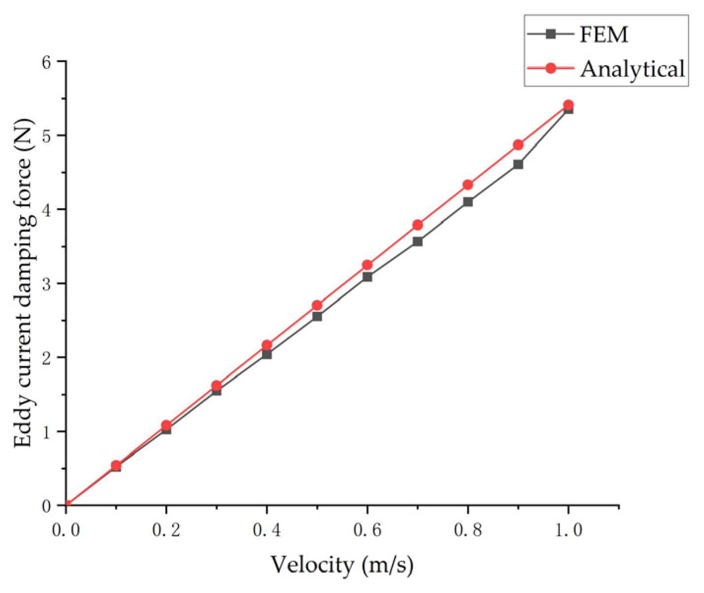
5.1. Simulation Verification

Simcenter MAGNET is a powerful electromagnetic field (EMF) simulation solution. The analysis of the EMF of the motor is efficient and accurate, and it has powerful post-processing capabilities to produce force and loss curves for any part of the motor, which helps this paper to visually compare the losses and thrust fluctuations of the different cooling plates. Here, a 3D simulation model that is based on a permanent magnet synchronous linear motor equipped with a cooling system is shown in Figure 7. The 3D model not only verifies the validity of the new method, but also considers the impact of the shape of the waterway. In addition, the effect of the damping force on motion can be simulated.
Figure 8 shows the characteristics of the damping force of the water-cooled plate that were obtained using finite element analysis and the analytical calculation. It can be seen that the calculated values and the finite element method (FEM) values nearly match, which confirms the accuracy of the analytical method. Indeed, the analytical expression and the simulation diagram show that the damping force on the cooling plate varies proportionally with the velocity.
In the process of calculation and analysis, it is assumed that the air-gap magnetic field is sinusoidal. However, in fact, there is some distortion in the air-gap magnetic field—the calculated result is slightly larger than the simulated value.
Figure 9 shows the characteristics of the damping force, caused by the cooling plates of various structures, that were obtained using the FEM. It can be seen that the damping force of the cooling plate is significantly reduced after using the novel structure. Furthermore, the damping force decreased by more than 90% (compared to the conventional cooling plate) when the experimental motor was operated at rated velocity (i.e., the velocity was 1 m/s). In addition, the damping force of the new structure also increased with the increase of velocity. However, the growth rates of the novel structures were much lower than the growth rates of the conventional structure.
Furthermore, the 3D simulation produced a cloud chart of the eddy current loss distribution of the cooling plate, as shown in Figure 10. In this paper, we argue that the eddy current loss is generated by the relative motion between the permanent magnet and the cooling plate that is generated by eddy current induction. Stainless steel is conductive, which means there is resistance in the cooling plate. Since there is no additional current source on the cooling plate, the eddy current loss in the cooling plate is reflected as ohmic loss. The two losses are equal. At the same cooling capacity and motor environment, it can be observed that the eddy current was uniformly distributed throughout the cooling plate before cutting, and the eddy current power loss reached its peak. Nevertheless, after cutting, the eddy currents were mainly distributed in the water path, which greatly reduced the total eddy current loss.

5.2. Experimental Prototype and Experimental Verification

A prototype machine was built based on the previous design parameters. The primary of the linear motor contained an armature and a silicon steel sheet, which were encapsulated together using an insulating adhesive. The surface of the armature was covered with cooling plates, and a removable device was designed to facilitate the installation of different groups of cooling plates. The experimental platform for motor testing is shown in Figure 11. In this experiment, the electric actuator and the electric motor were linked by a force sensor, and the electric actuator pushed the mover at different speeds. The waveform output from the force sensor was the combined force of the cooling plate damping force and the rail friction force. Therefore, the damping force had to be separated from the measured value. Since the material that was selected for the cooling plate was stainless steel with a relative permeability of one, it can be seen that the normal force of the motor did not change. Consequently, it was only necessary to measure the friction force again at the same speed and without the cooling plate installed to separate the damping force.
Figure 12 shows the waveform of the resultant force of friction and the damping force that was measured by the force sensor when the operating speed of the mover was 1 m/s. The thickness of the selected metal plates was 1 mm. It can be observed that the average value of the waveform without the cooling plate (i.e., with only friction) was minimal. The installation of the conventional cooling plate had a large damping force. In contrast, the installation of the optimized cooling plate had a small damping force. In order to visually compare the magnitude of the damping force, it was necessary to separate the damping forces. The separation was carried out by averaging the data from each waveform for a number of selected periods while running at a uniform speed. Furthermore, the average of the measurements was subtracted from each average when there was no plate.
Figure 13 shows the waveform of the eddy current damping force with velocity after separation. The figure shows that the damping force of the cooling plate was proportional to the operating speed. At the speed of 1 m/s, the damping force of the novel cooling plate was reduced by more than 70% (compared to the conventional cooling plate). Hence, it is verified that both of these novel cooling plate structures are effective in reducing the damping force.
Figure 14 shows the simulation values of the eddy current damping force when the thickness of the cooling plate was selected as 3 mm. Compared with the damping force of the 1 mm thick cooling plate, it can be seen that the damping force increased with the increased thickness of the cooling plate. The increase in the damping force of the two optimized structures was small. At a cooling plate thickness of 3 mm, the novel cooling plate structure suppressed 93.5% of the eddy damping force. When the thickness of the cooling plate increased, the suppression of the eddy current damping force became more obvious.
The experimentally measured eddy current damping force waveform of the 3 mm thick cooling plate is shown in Figure 15. It can be observed that the values of the experimentally obtained damping force were in general agreement with the simulation values. The waveform that was obtained from the novel structure was slightly larger than the simulation value because of the measurement error that was caused by the low accuracy of the force sensor, due to the limited experimental conditions. The novel structure with a thickness of 3 mm at the rated speed had a damping force suppression rate of over 80%. In summary, the conclusions that were obtained from the experiments are consistent with the simulation values to verify that the novel cooling plate structure can be applied to different thicknesses of cooling plates. Additionally, the larger the thickness, the more obvious the suppression of the eddy current damping force.

6. Conclusions

In this paper, a new cooling structure for a long primary permanent magnet linear motor was proposed, based on an analytical model of the eddy current damping force and the analytical results regarding the eddy force of a cooling structure. The following conclusions can be made on the basis of the obtained experimental and analytical results, and their analysis:
(1)
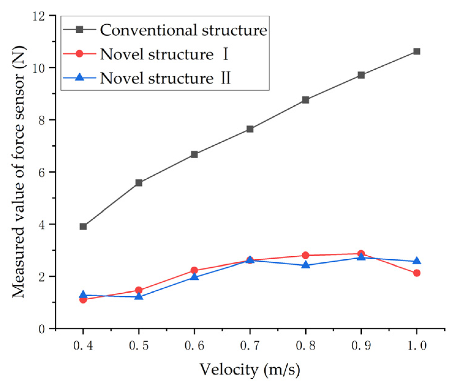
Both the simulation and experimental results verified the accuracy of the analytical expression of the damping force, and the damping force of a cooling plate is proportional to both speed and thickness;
(2)
The new water-cooled cooling plate structure can significantly reduce the damping force. The thicker the water-cooled plate, the more obvious the effect. Compared to an unoptimized 3 mm water-cooled plate, the proposed method can suppress the damping force by more than 80%.
In this paper, a cooling plate structure that can effectively suppress the eddy current damping force was proposed, although the eddy damping force still exists. Meanwhile, this structure has a large impact on the strength of the cooling plate. The goal of subsequent work is further optimization of the cooling plate cutting method. In the future, the GA-QN (genetic algorithm-quasi Newton) method will be used. The positions of each cut line can be used as parameters, and the GA solution can be used in the QN optimization method as the initial condition to correctly track the local optimal solution of the model parameters [23,24]. The GA-QN method overcomes the difficulty of applying only local determinism in the choice of the initial conditions. This method substantially reduces the complexity of the computation. Finally, the optimized structure is obtained.

Author Contributions

Conceptualization, M.W. and Q.S.; methodology, M.W.; software, Q.S.; validation, M.W., Q.S. and K.K.; formal analysis, L.L.; investigation, L.L.; resources, L.L.; data curation, Q.S.; writing—original draft preparation, M.W.; writing—review and editing, K.K.; visualization, Q.S.; supervision, L.L.; project administration, L.L.; funding acquisition, M.W. All authors have read and agreed to the published version of the manuscript.

Funding

This work was supported in part by the National Natural Science Foundation of China (Grant No. 52077041, Grant No. 51690182).

Institutional Review Board Statement

Not applicable.

Informed Consent Statement

Not applicable.

Data Availability Statement

Not applicable.

Conflicts of Interest

The authors declare no conflict of interest.

References

  1. Bertola, L.; Cox, T.; Wheeler, P.; Garvey, S.; Morvan, H. Thermal Design of Linear Induction and Synchronous Motors for Electromagnetic Launch of Civil Aircraft. IEEE Trans. Plasma Sci. 2017, 45, 1146–1153. [Google Scholar] [CrossRef]
  2. Quan, K.B.; Zhen, H.X.; Hong-Xing, W.; Li-Yi, L. Thrust and Thermal Characteristics of Electromagnetic Launcher Based on Permanent Magnet Linear Synchronous Motors. IEEE Trans. Magn. 2009, 45, 358–362. [Google Scholar] [CrossRef]
  3. Galea, M.; Buticchi, G. Development of a High Force Density, Actuation Drive for an Aerospace Application. In Proceedings of the 2018 IEEE 27th International Symposium on Industrial Electronics (ISIE), Cairns, QLD, Australia, 13–15 June 2018; pp. 372–377. [Google Scholar] [CrossRef] [Green Version]
  4. Galea, M.; Gerada, C.; Raminosoa, T.; Wheeler, P. Design of a high force density tubular permanent magnet motor. In Proceedings of the XIX International Conference on Electrical Machines—ICEM 2010, Rome, Italy, 6–8 September 2010; pp. 1–6. [Google Scholar] [CrossRef]
  5. Amoros, J.G.; Andrada, P.; Blanque, B.; Marin-Genescà, M. Influence of Design Parameters in the Optimization of Linear Switched Reluctance Motor under Thermal Constraints. IEEE Trans. Ind. Electron. 2017, 65, 1875–1883. [Google Scholar] [CrossRef] [Green Version]
  6. Park, K.-S.; Choi, J.; Park, Y.-P.; Park, N.-C. Thermal Deformation of Thermally Assisted Magnetic Recording Head in Binary Gas Mixture at Various Temperatures. IEEE Trans. Magn. 2013, 49, 2671–2676. [Google Scholar] [CrossRef]
  7. Ruoho, S.; Kolehmainen, J.; Ikaheimo, J.; Arkkio, A. Interdependence of Demagnetization, Loading, and Temperature Rise in a Permanent-Magnet Synchronous Motor. IEEE Trans. Magn. 2009, 46, 949–953. [Google Scholar] [CrossRef]
  8. Jang, C.; Kim, J.Y.; Kim, Y.J.; Kim, J.O. Heat transfer analysis and simplified thermal resistance modeling of linear motor driven stages for SMT applications. IEEE Trans. Components Packag. Technol. 2003, 26, 532–540. [Google Scholar] [CrossRef]
  9. Pei, Z.; Zhao, J.; Song, J.; Zong, K.; He, Z.; Zhou, Y. Temperature Field Calculation and Water-Cooling Structure Design of Coreless Permanent Magnet Synchronous Linear Motor. IEEE Trans. Ind. Electron. 2021, 68, 1065–1076. [Google Scholar] [CrossRef]
  10. Kandlikar, S.G.; Hayner, C.N. Liquid Cooled Cold Plates for Industrial High-Power Electronic Devices—Thermal Design and Manufacturing Considerations. Heat Transf. Eng. 2009, 30, 918–930. [Google Scholar] [CrossRef]
  11. Gholizad, H.; Funieru, B.; Binder, A. Direct Modeling of Motional Eddy Currents in Highly Saturated Solid Conductors by the Magnetic Equivalent Circuit Method. IEEE Trans. Magn. 2009, 45, 1016–1019. [Google Scholar] [CrossRef]
  12. Zheng, J.; Zhao, W.; Ji, J.; Zhu, J.; Lee, C.H.T. Sleeve design of permanent-magnet machine for low rotor losses. Chin. J. Electr. Eng. 2020, 6, 86–96. [Google Scholar] [CrossRef]
  13. Kou, B.; Jin, Y.; Zhang, H.; Zhang, L.; Zhang, H. Analysis and Design of Hybrid Excitation Linear Eddy Current Brake. IEEE Trans. Energy Convers. 2014, 29, 496–506. [Google Scholar] [CrossRef]
  14. Jin, Y.; Kou, B.; Li, L.; Li, C.; Pan, D.; Song, K. Analytical Model for a Permanent Magnet Eddy-Current Brake With Transverse Edge Effect. IEEE Access 2019, 7, 61170–61179. [Google Scholar] [CrossRef]
  15. Ebrahimi, B.; Khamesee, M.B.; Golnaraghi, F. A novel eddy current damper: Theory and experiment. J. Phys. D Appl. Phys. 2009, 42. [Google Scholar] [CrossRef]
  16. Ebrahimi, B.; Khamesee, M.B.; Golnaraghi, F. Permanent magnet configuration in design of an eddy current damper. Microsyst. Technol. 2008, 16, 19–24. [Google Scholar] [CrossRef]
  17. Johan, S.A. Lithographic Actuator Mechanism, Lithographic Apparatus, and Device Manufacturing Method. U.S. Patent 797618, 4 November 2004. [Google Scholar]
  18. Pan, D.; Li, L.; Wang, M. Modeling and Optimization of Air-Core Monopole Linear Motor Based on Multiphysical Fields. IEEE Trans. Ind. Electron. 2018, 65, 9814–9824. [Google Scholar] [CrossRef]
  19. Belli, Z. Optimization of stator slots shape for eddy current losses reduction in permanent magnets synchronous machine. In Proceedings of the 2014 Ninth International Conference on Ecological Vehicles and Renewable Energies (EVER), Monte-Carlo, Monaco, 25–27 March 2014; pp. 1–7. [Google Scholar] [CrossRef]
  20. Smajic, J.; Cranganu-Cretu, B.; Kostinger, A.; Jaindl, M.; Renhart, W.; Magele, C. Optimization of Shielding Devices for Eddy-Currents Using Multiobjective Optimization Methods. IEEE Trans. Magn. 2009, 45, 1550–1553. [Google Scholar] [CrossRef]
  21. Kou, B.; Jin, Y.; Zhang, H.; Zhang, L.; Zhang, H. Nonlinear Analytical Modeling of Hybrid-Excitation Double-Sided Linear Eddy-Current Brake. IEEE Trans. Magn. 2015, 51, 1–4. [Google Scholar] [CrossRef]
  22. Singh, A. Theory of eddy-current brakes with thick rotating disc. Proc. Inst. Electr. Eng. 1977, 124, 373–376. [Google Scholar] [CrossRef]
  23. Morris, W.J.; Tyldesley, S.; Rodda, S.; Halperin, R.; Pai, H.; McKenzie, M.; Duncan, G.; Morton, G.; Hamm, J.; Murray, N. Androgen Suppression Combined with Elective Nodal and Dose Escalated Radiation Therapy (the ASCENDE-RT Trial): An Analysis of Survival Endpoints for a Randomized Trial Comparing a Low-Dose-Rate Brachytherapy Boost to a DoseEscalated External Beam Boost for High- and Intermediate-risk Prostate Cancer. Int. J. Radiat. Oncol. Biol. Phys. 2017, 98, 275–285. [Google Scholar] [CrossRef]
  24. Zhang, C.; Zhang, C.; Li, L.; Guo, Q. Parameter analysis of power system for solar-powered unmanned aerial vehicle. Appl. Energy 2021, 295, 117031. [Google Scholar] [CrossRef]
Figure 1. The topology of a long primary linear synchronous motor.
Symmetry 13 02025 g001
Figure 2. Model diagram of the distribution of the magnetic field.
Symmetry 13 02025 g002
Figure 3. Cooling plate cutting schematic.
Symmetry 13 02025 g003
Figure 4. Optimized cutting method II.
Symmetry 13 02025 g004
Figure 5. Cooling plate 3D diagram: (a) novel structure I; (b) novel structure II.
Symmetry 13 02025 g005
Figure 6. Segmented cooling plates.
Symmetry 13 02025 g006
Figure 7. Simulation model of PMLSM.
Symmetry 13 02025 g007
Figure 8. Comparison of simulated and calculated eddy current damping force.
Symmetry 13 02025 g008
Figure 9. Simulation results of the eddy current damping force.
Symmetry 13 02025 g009
Figure 10. Eddy current distribution: (a) conventional structure; (b) novel structure.
Symmetry 13 02025 g010
Figure 11. Experimental platform.
Symmetry 13 02025 g011
Figure 12. Force sensor measurement waveform.
Symmetry 13 02025 g012
Figure 13. Experimental measurement of the eddy current damping force waveform.
Symmetry 13 02025 g013
Figure 14. Simulation waveform of the eddy current damping force of a 3 mm thick cooling plate.
Symmetry 13 02025 g014
Figure 15. Waveform of the eddy current damping force of a 3 mm thick cooling plate.
Symmetry 13 02025 g015
Table 1. Specifications of the linear motor.
SymbolQuantityValue
L m Length of permanent magnet 26 mm
h m Height of permanent magnet11.5 mm
N Turns of exciting winding196
L Length of primary iron core1 m
b Width of primary iron core80 mm
b t Tooth width41.7 mm
H Height of primary core yoke5 mm
δ Air gap length0.5 mm
τ Pole pitch31.25 mm
c Water-cooled plate thickness1 mm
σ Conductivity1.4 × 106 S/m
Publisher’s Note: MDPI stays neutral with regard to jurisdictional claims in published maps and institutional affiliations.

