Abstract
The turn domain resampling (TDR) method is proposed in the paper on the basis of the existing angle domain resampling for solving the problem of non-fixed fault frequency under variable working conditions. TDR can select the appropriate sampling order according to the influence of frequency conversion, which avoided the error caused by the spline interpolation method. It can provide accurate parameters for the subsequent calculation of the equivalent frequency order. Variable multi-scale morphological filtering (VMSMF) method is proposed for the purpose of further reducing the interference of noise in resampling signal to feature extraction. VMSMF adaptively selects structural elements according to the parameter change of impact signal to make its scale more targeted. It only needs to calculate once using the optimal structural unit for a particular impact, and the filtering accuracy and operating efficiency have been greatly improved. The main steps of this article are as follows. First, the TDR is used to resample the original signal as to get the resampling signal which is still submerged by the strong noise. In the second step, VMSMF is used to filter the resampling signal to obtain the signal with less noise interference. Finally, the fault characteristics of the filtering signal was extracted and compared with the possible fault frequency calculated by the sampling parameters provided by resampling, so as to determine the fault type of the planetary gearbox. By analyzing the simulation signal and the experimental signal respectively, this method can find out the corresponding fault characteristics effectively.
1. Introduction
Planetary gear transmission is widely used in many mechanical transmission systems, including simple machinery and complex equipment, from micro-electromechanical Systems (MEMS) to marine engineering equipment [1,2,3]. Their working states are almost ubiquitous, but they are different. Due to the harsh working environment and complex structure of the planetary gear system, faults such as gear tooth crack and spalling have often occurred in the operation process, and the faults caused the system to shut down. Thus, it is of great significance to study the fault diagnosis of gear damage in planetary gear system.
For the planetary gearbox running at a constant speed, the input or output speed of the gearbox will fluctuate due to the influence of external load and other factors; for some specific working conditions, the required speed must be changed according to the predetermined setting. In view of the above conditions, the feature frequency extracted by traditional signal fault feature extraction method will produce serious frequency ambiguity, which is difficult to effectively judge the fault. This leads to the limitations of traditional methods when dealing with signals of variable conditions. So, it is very important to put forward a method to avoid the effect of speed change on the processing result. Considering that the planetary gearbox is a rotating device, if the sampling interval can be used as a specific rotation angle, the signal collected is steady-state signal relative to the rotation field no matter how the speed of the planetary gearbox changes. Based on this theory, angle domain resampling technology emerged as the times require, and this method can effectively avoid the phenomenon of “frequency ambiguity”. Fyfe K.R. et al. [4] proposed the hardware order tracking technology to synchronize the signal sampling frequency with the rotation speed to ensure the same number of sampling points in each rotation period. However, this scheme is all realized by hardware, which is not applicable to sites where it is difficult to install field equipment. Moreover, the sampling accuracy is significantly decrease when the rotation speed changes frequently [5]. In 1989, Potter et al. [6] developed a resampling method which called computed order tracking (COT). Bossley K.M. et al. [7] researched a spline interpolation algorithm to obtain the equal-angle sampling sequence of the Angle domain. In 2002, Guo and Qin et al. [8] of Chongqing University proposed an order tracking technology based on instantaneous frequency estimation. In 2005, Bonnardot et al. [9] of the University of Lyon in France proposed a method of order tracking based on narrow band demodulation. In 2007, Combet et al. [10] of Cranfield University researched a method for automatic selection of meshing frequency harmonics. In 2011, Wang et al. [11] from the University of Pretoria, South Africa proposed tacholess order tracking (TLOT) strategy based on EMD. In 2012, Randall et al. [12] from the University of South Wales, Australia, extracted the phase information of the converter harmonics step by step through the iterative method to realize TLOT. In 2013, Zhao et al. [13] proposed a TLOT method based on Vold–Kalman filtering. In 2017, Feng et al. [14] applied Vold–Kalman filter to wind driven generator gearbox fault diagnosis research. In 2019, li et al. [15] from Northwestern Polytechnical University proposed a wind driven generator fault diagnosis method based on Vold–Kalman filtering and multi-scale sample entropy.
The maximum sampling order was mostly selected based on empirical selection in most of the existing studies. As a result, the resampled signal may have had redundant or missed fault characteristics. The sampling points and the sampling frequency of resampling signal are different from the original time-domain signal, but the traditional method did not give the relevant parameters of the resampling signal, there are some limitations in the subsequent calculation process. The traditional order tracking method adopts spline interpolation in the reconstruction of the angular domain signal, the spline interpolation algorithm assumes that the rotation speed in a certain interval is constant rotation speed, which will cause a certain error to the resampled signal. The TDR method proposed in this paper accurately calculates the corresponding value of each point that needs to be sampled. Rotation speed and angular displacement effectively reduce the reconstruction error caused by spline interpolation. In view of the above problems, this paper improved the existing COT method, and thus can better solve the above problems.
During the movement of the planetary gear system, the sun gear, planetary gear and planet carrier generally move together, the ring gear is stationary, and the sensor is installed on the box when the signal is collected. The meshing point of solar wheel-planetary wheel and planetary wheel-gear ring changes periodically with the relative position of sensor, the transmission path of meshing signal to sensor is complex; the planetary gear train simultaneously meshes multiple pairs of gears simultaneously, so the collected signals are mostly modulation signals. For the complex fault signal of planetary gear system, especially the early weak fault, it is easy to be submerged by the strong noise, so the early-stage vibration signal needs to be denoised to highlight the fault characteristics. Morphological filtering (MF) is a nonlinear filtering method which can keep the main morphological characteristics. This method is simple, reliable, and effective, and has been widely used in vibration signal analysis and processed of rotating equipment. Scholars at home and abroad have carried out a series of researches on filter scale and structural element selection, and they have obtained certain results. In 2003, Athenian scholar Nikolaou et al. [16] set the length of structural elements as 0.6~0.7 times of the ratio of sensor sampling frequency to fault characteristic frequency. In 2008, Zhang et al. [17] used triangular SE multi-scale morphological analysis to extract the characteristics of impulse signals from signals with strong background noise. Song et al. [18] proposed the combination of the trivalent logic inference theory with the possibility and fuzzy theories. Cui et al. [19] proposed a new concatenated dictionary matching tracking method combining impact dictionary and step dictionary. In 2011, Dong et al. [20] took the maximum signal-to-noise ratio (SNR) as an indicator of the selection scale. The single-scale MF is selected in the above study, which has an obvious effect when dealing with a single vibration signal, but its effect is greatly reduced when dealing with a complex vibration signal. In 2017, Zuo et al. [21] used diagonal slice spectra to assist multi-scale morphological filter (MSMF) to analyze bearing fault signals. In 2018, Li et al. [22] selected hamming window as the structural element and took the arithmetic average of filtering results of all scales as the final filtering output. In 2019, Luo et al. [23] proposed an adaptive multi-scale enhanced combined gradient morphological filtering method and applied to bearing noise signal with good results. This method only provided a variety of operation combinations in the mathematical morphology algorithm, and the traditional method is still used in the selection of structural elements. In 2019, Cui et al. [24] proposed a multi-scale morphological filtering method for bearing signals.
MSMF is better than single-scale morphological filter in feature extraction of complex vibration signals. However, the selection of element scale of MSMF structure is based on the characteristics of multi-group characteristic impulse signals, which results in the amplification of part of the signal shock and the weakening of part of the signal shock during the filtering. This processing method leads to the distortion of the filtered signal. In addition, when MSMF is selected, there has a problem of repeatedly calling scales in the calculation of multiple scales, which results in a large amount of calculation and affects the calculation efficiency. In view of the above problems, the variable multi-scale morphological filtering (VMSMF) method is proposed in this paper. Chebyshev window is selected as the structural element in this paper, and the scale of structural elements is determined according to the peak-to-peak value of signal characteristics. For specific data signals, only the optimal scale of structural elements is selected for calculation according to their own judgment, which improves the calculation efficiency. VMSMF has greatly improved the noise reduction effect and computational efficiency of planetary gearbox fault signal.
The proposed method based on the turn domain resampling (TDR) and VMSMF can effectively reconstruct the unsteady signal and de noise the fault signal with strong noise, so as to obtain the fault characteristics reflecting the fault characteristics. Firstly, the paper used the TDR to reconstruct the filter signal. Secondly, the extremum points of the original signal were found, accorded their types to determine the analysis method, and the Chebyshev structural element scale libraries of different scales according to the signal characteristics were designed. Thirdly, the paper selected appropriate structural element scales in the structural element scale library according to different impact characteristics, and we used morphological open-close and closed-open average combination filters to process the original signals. Finally, we calculated the fault characteristics of the filter signal to determine the existence of fault.
Other parts of this paper are organized as follows. In the second part, the basic theory of TDR and VMSMF is introduced. The third part carries on the verification analysis of the gear simulation signal. The fourth part analyzes the signals of different fault types of gear. The fifth part expounds the conclusion of this paper.
2. Theoretical Introduction
2.1. Turn Domain Resampling Technique
The order tracking algorithm is a technology developed in recent years. The main purpose of the method is to transform the equal time interval signal into the equal angle interval signal by re-picking the time-domain signal. The traditional COT method adopted the spline interpolation algorithm and generally set the maximum sampling order according to the empirical value [25,26]. If the maximum sampling order was not selected properly, the resampling signal may be distorted or repeatedly sampled. Moreover, the COT method is also limited to some extent when extracting and reconstructing the signals of certain order components for subsequent analysis and processing. In view of the above problems, this paper proposed a turn domain resampling method based on signal characteristics and speed characteristics changes. Its main working principles and steps are as follows.
Firstly, the optimal sampling order is determined. The optimal sampling order is to ensure the integrity of the characteristic information of the resampling signal.
(1) The sampling order must satisfy the lowest sampling order. According to the Shannon sampling theorem, the lowest sampling order must be no less than two times the highest order.
where —lowest sampling order; —maximum order of resampling signal; —minimum sampling frequency of time domain signal; —maximum speed of input shaft.
To ensure the integrity of the sampled signal, the original time domain signal sampling frequency should not be less than the minimum sampling frequency. Thence, in order to ensure that the resampling signal contains complete fault characteristic information, a higher sampling frequency should be selected when obtaining the original time domain signal.
(2) In order to ensure that the sampling points was not repeated and there were no empty points, it was necessary to set the optimal sampling order of resampling, that is, the number of sampling points per revolution of the input axis. As shown in Figure 1, it showed the influence of the selection of inappropriate sampling order on the sampling effect, the red circle represents the points that do actually exist after resampling, while the green circle represents the points that do not actually exist after resampling. Figure 1a showed the condition that the sampling order was too low, some points of resampling signal were missed, so the signal characteristics cannot be accurately described. Figure 1b shows the situation of an excessively high sampling order, and according to the principle of related sampling, the repeated sampling did not only waste the subsequent computing efficiency, but also affected the performance of signal feature description.
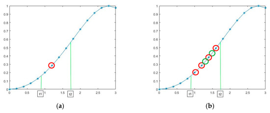
Figure 1.
Schematic diagram of sampling order selection. (a) Sampling order is too low, (b) sampling order is too high.
To select the optimal sampling order, it is necessary to know the frequency variation function of the original signal in advance, and derive the value of the optimal sampling order according to the frequency conversion function. Suppose the function of the input shaft speed of the gearbox with time is:
where —the initial velocity of the input axis; , —related parameters of speed change.
The optimal sampling order is set as function (3):
Secondly, the paper set the total number of sampling points. In the light of angular displacement of the input axis and the optimal sampling frequency to obtain the sampling points.
The angular displacement of the input axis is calculated by integrating the input axis rotation function. In the actual situation, the conversion curve often changes irregularly, so it is difficult to fit the corresponding conversion curve function equation. Without loss of generality, in this paper, the conversion curve is equivalent to the superposition of multi-segment functions, and the integral solution was carried out for each segment function. All the calculated angular displacements are accumulated to obtain the total angular displacements of the input axis.
Finally, we formulated the sampling rules. This paper adopted the nearest point principle to reconstruct the vibration signal at the relevant sampling time in the original signal but abandoned the original spline interpolation method. Last, the angular domain resampling signal is obtained. As shown in Figure 2, the resampling signal location is mainly divided into two cases. In Figure 2a, the location of resampling signal coincides with the original signal, and the original signal is selected as the resampling signal point. In Figure 2b, the resampling position is between two adjacent original signal points, the distance between the resampling signal and the two original signal points is L1 and L2, respectively. The selection method is shown in function 4.
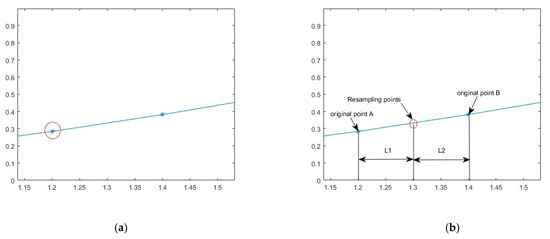
Figure 2.
Schematic diagram of resampling signal selection. (a) The resampling position coincides with the original signal position; (b) The resampling position is between two adjacent points.
2.2. Structural Elements and Morphological Algorithms
2.2.1. Structural Elements
The selection of structural elements depended on the morphological characteristics of the original signal. The two key elements of structural elements are length and height. Linear and triangular structural elements are widely used in vibration signal processing of rotating equipment. The height of linear structural elements is zero, and only its length changed. The length and height of triangular structure elements will vary with the size, and the analysis effect is better than that of linear structure. However, the length of triangular structure elements can only be odd, which is discontinuous in the length direction and cannot be matched accurately. The essence of linear and triangular structural elements is rectangular and triangular Windows. There are two main indexes to evaluate a window function as structural element: (1) The width of the main lobe should be as small as possible; (2) the side lobe height as low as possible. The side lobe of rectangular window and triangular window are larger than others, so there are certain defects. In this paper, several common window functions were compared to find the optimal window function as the structural element. Common window functions include rectangular window, triangle window, Hanning window, Hamming window, Blackman window, Chebyshev window, Tukey window, etc. MATLAB software was used to draw the time-domain waveform and FFT spectrum diagram of the above window function, as shown in Figure 3. Figure 3a is the time domain waveform of each window function, and Figure 3b is its FFT spectrum diagram.
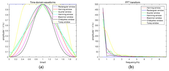
Figure 3.
Time-frequency waveforms of each window function. (a) Time domain waveforms, (b) frequency domain waveform.
The main lobe width is defined as the distance from zero to the first intersection of the spectral response curve in the spectrum diagram. As can be seen from Figure 3, the main lobe width of Chebyshev window function is the smallest, and the height of the side lobe is the shortest, which is most consistent with the condition of being a structural element.
In order to further verify the superiority of this structural element, different window functions were selected as structural elements of morphological filtering to filter the signals. The correlation coefficients of filtering signals and original signals were calculated for different groups of data, as shown in Table 1.

Table 1.
Coefficient of association between the original signal and the filtered signal.
Table 1 was the coefficient of association between the original signal and the filtered signal. Different window functions are used as structural elements of MF to filter the original signal. According to the data in Table 1 and Figure 4, the corresponding correlation of Chebyshev window was the largest and the most stable. This also confirms the correctness of the selection criteria of MF structural elements, so the Chebyshev window function was chosen as the structural element in this paper.
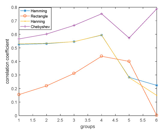
Figure 4.
Correlation coefficient of morphological filtering signal.
Chebyshev window structural elements (CSE) are expressed as:
where α and β in the equation are as follows:
where N is the length of CSE, α determine the attenuation degree of the side lobe, according to the literature review, . In order to make the set morphology of structural elements and the original signal more uniform, this paper calculates the coefficient ai according to the peak and trough value of each impact of the original signal in actual operation, so as to make the filtering result more accurate. The following table shows the structural elements of each scale.
In Table 2, n represents the scale size. According to experience, the size of the single impact scale is generally not greater than 30. In this paper, the maximum scale was selected as 50, and a scale library of n = 50 is established for call.

Table 2.
The scales library of CSE structure element.
2.2.2. Mathematical Morphology
Mathematical morphology characterizes and analyzes signals from a geometric perspective [27,28]. The biggest advantage lies of mathematical morphology in its direct relationship with geometry, and this explicit geometric description gives it a unique advantage in the representation of vibration signals. Expansion and corrosion are two basic transformations in mathematical morphology. Suppose the original signal is , and the structural elements are . Expansion is the process of merging all background points in contact with an object into that object, corrosion is the process of eliminating all boundary points of an object which resulting in the remaining object being one pixel smaller than the area of the original object along its periphery. The expansion and corrosion of with respect to were defined as in [16].
where, and represent the expansion and corrosion, respectively.
The open and closed operations of on were expressed as:
where and represent the open and closed operations, respectively.
In general, the cascade of open and closed operations was mainly used to remove both positive and negative noises in the signal. Maragos defines morphological open-close and closed-open filters.
where oc and co represent open and closed operations, respectively.
In order to suppress statistical bias, morphological open-close and closed-open mean combination filters were used in this paper.
2.3. Variable Multi-Scale Morphological Filtering (VMSMF)
In the traditional MSMF, when the original signal was filtered by various scales, each shock was calculated in accordance with each scale, which reduces the calculation efficiency. In addition, the scale of structural elements cannot adapt to all shocks during the calculation, thereby reducing the filtering accuracy. To solve the above problems, variable multi-scale morphological filtering (VMSMF) method is proposed in this paper. The method aimed at a specific shock of the original signal only need to calculate once, and for different shocks in the signal, the corresponding structural element scale is selected. The specific steps are as follows:
(1) Establishing a CSE scale library with a maximum scale of 50 for subsequent calls.
(2) Finding all the maxima and minima of the original signal, the number of extreme points is denoted as Nm and Ni, respectively. Calculating the number of discrete points between adjacent minima.
(3) The two ends of the original signal are cut off according to the distribution characteristics of the maximum and minimum points. The distribution characteristics between the maximum and minimum points can be divided into four types, as shown in Figure 5.
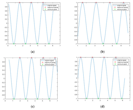
Figure 5.
Distribution of extreme points of time-domain signals: (a) represents one more minimum point than maximum point, (b) means that the minimum point is one less than the maximum point, (c) means that the minimum point first appears when the minimum point and the maximum point are the same, (d) indicates that the minimum point and the maximum point are the same, with the maximum point appearing first.
- ①
- Ni − Nm = 1, to analyze from the first impact to the end of the last impact;
- ②
- Ni − Nm = −1, discard the head and tail impact and analyze the middle part;
- ③
- Ni = Nm& the minimum occurs first, discard the last shock signal and analyze the rest;
- ④
- Ni = Nm& the maximum occurs first, discard the first shock signal and analyze the rest.
(4) For the KTH impact of the original signal, the number of discrete points between the two minimum points corresponding to the impact signal is selected as the length of CSE, as shown in Figure 6.
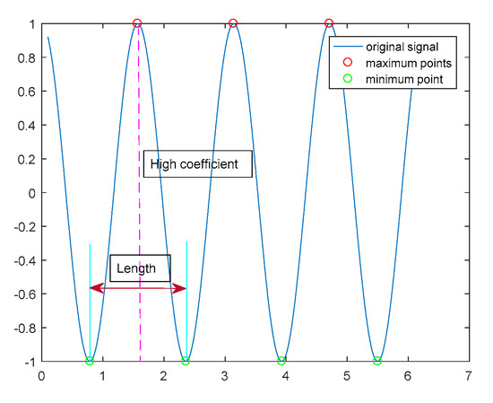
Figure 6.
Schematic diagram of filter parameter selection.
(5) The peak-to-peak value between the maximum value and the minimum value of the impulse signal is taken as the height coefficient ai of CSE, and the arithmetic mean value of the amplitude of the two minimum points of the impulse signal is taken as the minimum value.
(6) In the light of the characteristic parameters of shock signals calculated in steps 4 and 5, selected appropriate structural elements and filtered the shock signal.
(7) Repeat steps 4–6 until all shock signals analysis is completed, and finally integrate the filtering signals of all shock signals to obtain the MF signals of the original signals. Herein, it should be noted that the minimum points are calculated once for each of the two adjacent shock signals, respectively. In order to make the signals more accurate, this paper mean value of the two values is calculated as the filter value of this point.
3. Simulation Signal Analysis
So as to verify the effectiveness of the proposed method, the simulation signals with white gauss noise is analyzed in this paper. Equation (15) is the simulation signal equation. The simulation equation simulated the sun wheel fault. It mainly consisted of planet carrier amplitude modulation of rotation, sun wheel amplitude modulation of rotation, sun wheel fault amplitude modulation, sun wheel fault frequency modulation and noise signal. The sampling frequency of the simulation equation was 10,000 Hz, the sampling time was 5 s, and the maximum speed of the input shaft was 1200 r/min. The main parameters of each gear in the specific analog gearbox were shown in Table 3.
where, is the rotation frequency of the planetary shelf; is the absolute rotation frequency of the solar wheel; is the fault characteristic frequency of solar wheel; is the meshing frequency of the sun wheel; is the input axis angular velocity; are amplitude and phase coefficients, respectively. Without loss of generality, white gauss noise with a signal-to-noise ratio of 10 was added to the simulation signal. Figure 7 and Figure 8 showed the time domain waveform and FFT transformation diagram of the original signal and resampling signal, respectively. It can be seen from Figure 7b that the frequency spectrum analysis of time-domain signals of variable working conditions was conducted directly. The rotation speed of the input shaft is shown in Figure 9. Due to the signals of complex and diverse frequency components and severe frequency ambiguity, the fault characteristics could not be extracted.

Table 3.
The parameters of planetary gearbox.
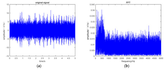
Figure 7.
Original time domain signal and FFT transformation. (a) Original time domain signal. (b) FFT transformation of the original signal.
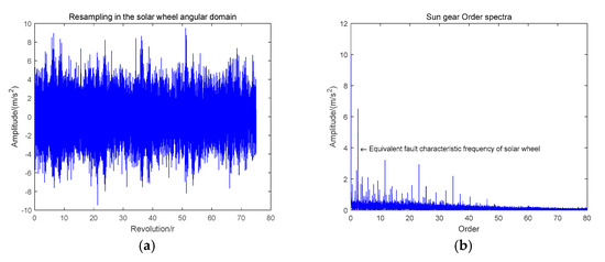
Figure 8.
Resampling signal and FFT transform. (a) Resampling signal. (b) FFT transform of resampling signal.
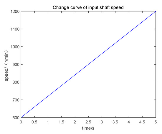
Figure 9.
Change curve of input shaft speed.
The turn domain resampling signal was equal Angle domain signal, compared to the original signal, the sampling frequency of the resampling signal was the number of sampling points per revolution of the input axis. The equivalent fault characteristic frequency of sun wheel fault as follows.
where, is the equivalent sun wheel fault characteristic frequency; is the number of ring gear teeth; is the number of sun gear teeth; is the number of planetary rings.
Figure 8 was the resampling signal and the resampling FFT transformation diagram of sun wheel fault. The equivalent frequency of 2.5 Hz can be found from Figure 8b. Therefore, the effectiveness of the method can be verified. It can be seen that from Figure 8b, in addition to the initial equivalent failure frequency in the envelope spectrum, there was also an impact at 11.5 Hz, and the impact was relatively obvious. For preserve only the fault signal of the sun wheel in the resampling signal, the way of the VMSMF is used which proposed in this paper to further reduce the noise.
It can be seen from Figure 10 that, by comparing the envelope spectrum before and after filtering, both can clearly reflect the equivalent fault characteristic frequency of the sun gear fault. However, the noise frequency of the filtered signal is better suppressed, and only the equivalent fault characteristic frequency is retained. The frequency peak near 11.5 Hz is also effectively suppressed. The validity of the proposed VMSMF algorithm is verified.
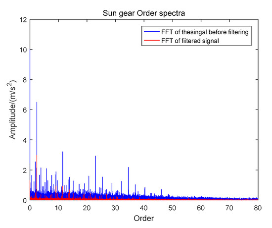
Figure 10.
Spectrum envelope before and after VMSMF.
In order to verify the effectiveness of the method proposed, the paper analyzed the simulation signal by selecting the Hanning window, Hamming window MSMF and the method in this paper. In the Figure 11a,b, Hanning window and Hamming window are used to filter the signal respectively. It can be seen from the figure that although the two methods can identify the fault characteristic frequency in the noise interference, the difference between the interference frequency and the fault frequency in the above two methods is not particularly obvious. It can be seen from (c) and (d) in the figure that the fault characteristic frequency of MSMF and VMSMF can be more significantly distinguished than Hamming window and Hanning window. Compared with MSMF, VMSMF method can better suppress other interference frequency components except fault characteristic frequency. The analysis results showed that the method proposed in this paper is more capable of highlighting the fault characteristics, thus verifying the effectiveness of the method proposed in this paper.
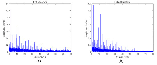
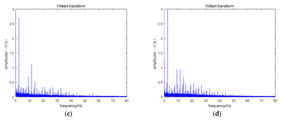
Figure 11.
Spectrum envelope used different ways. (a) Used Hanning windows as structural elements. (b) Used Hamming windows as structural elements. (c) Used MSMF as structural elements. (d) Used VMSMF as structural elements.
In order to further compare the operation efficiency of VMSMF compared with MSMF, the paper calculates and analyzes the data signals with different sampling points, and the results of operation time are shown in Table 4.

Table 4.
Comparison of computing time between VMSMF and MSMF.
As can be seen from the data in Table 4, compared with MSMF, VMSMF has greatly improved the operation speed for all points. Therefore, it can be seen that the proposed method greatly improves the operation efficiency.
4. Experimental Signal Verification
To further verify the effectiveness of the method presented in the paper, the powertrain fault diagnosis integrated test bench (Spectra Quest, Charlottesville, VA, USA) data shown in Figure 12 was used for testing. The laboratory furniture consists of speed control device, drive motor, bearing seat, secondary planetary gearbox, fixed shaft gearbox, load device and so on. Relevant parameters of each gear in the planetary gearbox are consistent with simulation signal parameters, as shown in Table 3. Figure 13 showed the speed change of the input shaft of the gearbox. Figure 14 is a picture of the faulty gear. Data within 10–20 s are analyzed in the paper. The parameters set and calculated in the experiment are shown in Table 5.
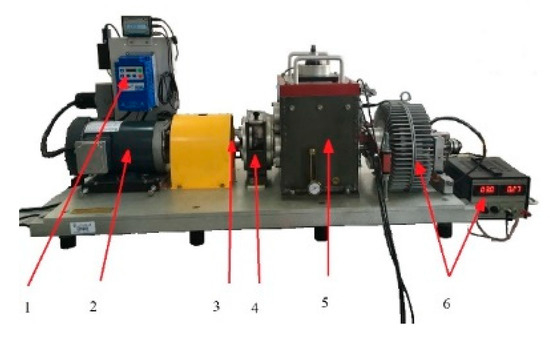
Figure 12.
Comprehensive test bench for power drive fault diagnosis. 1 peed control device, 2 drive motor, 3 bearing seat, 4 secondary planetary gearbox, 5 fixed shaft gearbox, 6 load device.
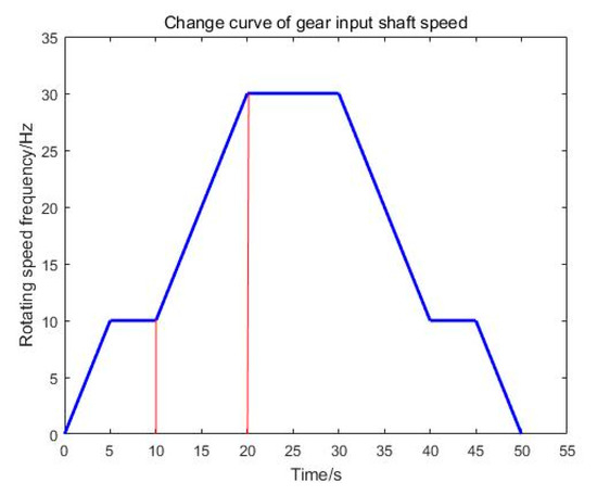
Figure 13.
Change curve of input shaft revolution frequency of planetary gearbox.
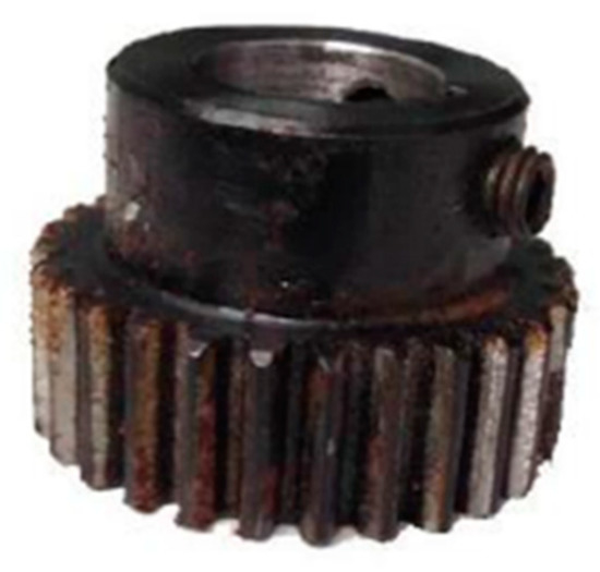
Figure 14.
Wear out faulty solar wheel components.

Table 5.
Relevant parameters of experimental signals.
This paper uses the proposed TDR and VMSMF methods to analyze the sun gear wear fault signal and health status signal respectively.
Firstly, transformed the original time domain signal by FFT. The time-domain signal and their FFT spectrum diagram were shown in Figure 15.
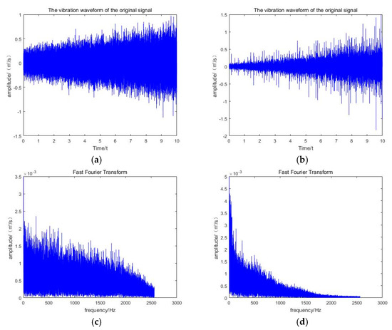
Figure 15.
The original signal of the planetary gearbox. (a) is the time domain signal of the original health components; (b) is the time-domain signal of the original solar wheel wear state; (c) is the FFT transform spectrum diagram of the original health components; (d) is the FFT transform spectrum diagram of the original solar wheel wear state.
Secondly, the original signals of the two states were resampled by TDR technique. The obtained resampling signal of resampling signal are shown in Figure 16.
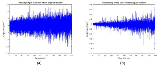
Figure 16.
Resampling angular domain signal and its envelope spectrum waveform. (a) the waveform of resampling signal in healthy state; (b) the waveform of the resampling signal for sun wheel failure.
Finally, filtered the resampling signal by VMSMF.
The paper used the proposed VMSMF method to filter the gearbox signals of two states, respectively. The filtering signal and FFT spectrum diagram were shown in Figure 17.
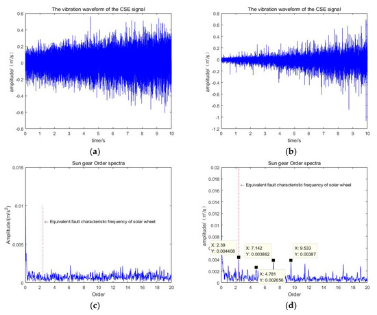
Figure 17.
VMSMF signal and its envelope spectrum waveform. (a) the waveform of filtering signal in healthy state; (b) the waveform of the filtering signal for sun wheel failure; (c) the FFT envelope spectra of health filtering signals; (d) the FFT envelope spectra of filtering signal for sun wheel fault.
The method based on TDR and VMSMF proposed in the paper is used to analyze the health state of planetary gearbox and the fault state signal of first stage solar wheel. As can be seen from Figure 17c,d, the signal of healthy state has no obvious frequency peak at the position of the equivalent frequency of solar wheel failure red mark. For the fault signal of sun wheel, the fault characteristic frequency was 2.39 Hz, 4.781 Hz, 7.142 Hz, and 9.533 Hz. According to the calculation method of the equivalent fault characteristic frequency of the planetary gearbox, the above frequencies correspond to the equivalent fault characteristic frequency of the sun gear and two, three, and four times of the frequency, and the noise is effectively suppressed. The effectiveness of the method is verified by analyzing the vibration signals of the planetary gearbox sun gear in each fault state.
5. Conclusions
The signal of planetary gearbox is complicated, the noise interference is serious, and it is in an unsteady state. In view of the limitations of existing methods in solving the above problems, a fault diagnosis method of planetary gearbox based on TDR and VMSMF is proposed. This method improved the limitation of existing methods and can effectively determine the fault of planetary gearbox.
1. The trans-domain resampling method based on the principle of nearest sampling point is proposed to solve the problem of large error of spline interpolation in existing order tracking methods. Accurate parameters and methods are provided for calculating the equivalent frequency.
2. In this paper, the Chebyshev window is selected as a new structure element, and the scale library of structure elements is set according to the signal impact characteristics. The calculation times of all shock signals in the resampling signal are changed from the original scale number to one. The VMSMF method in this paper greatly improves the filtering accuracy and computational efficiency.
3. Through the analysis of the simulation and experimental signals in this paper, it is concluded that the method in this paper can effectively identify the fault of the planetary gearbox, thus verifying the effectiveness of the method in this paper.
Through the analysis found that, in this paper, based on TDR and VMSMF technology of combining the planet gearbox fault diagnosis method can effectively identify the planetary gearbox, gear fault for planetary gearbox fault diagnosis research put forward a new train of thought, has a certain theoretical guiding significance.
6. Discussion
The paper proposed a fault diagnosis method for the key components of the unsteady planetary gearbox based on TDR and VMSMF. By processing the simulation signal and the experimental signal separately, it can be seen that the method can eliminate the influence of the speed change and noise interference on the fault signal, and thus judge the fault. The way put forward a new train of thought about gear fault for planetary gearbox fault diagnosis research, and it has a certain theoretical guiding significance.
However, when performing TDR on the signal in this article, it is necessary to collect the speed signal of the device under test at the same time, which cannot be used in some cases where the speed cannot be measured. The above situation brings certain limitations to the application of this method. This research group will further study the method of extracting the speed change curve from the vibration signal.
Author Contributions
L.C. and T.L. conceived and designed the experiments. C.Z. and T.L. performed the experiments. T.L. and C.Z. analyzed the data; T.L. and L.C. provided guidance and recommendations for research; T.L. contributed to the contents and writing of the manuscript. All authors have read and agreed to the published version of the manuscript.
Funding
This research received no external funding.
Informed Consent Statement
Informed consent was obtained from all subjects involved in the study.
Data Availability Statement
Data available on request due to restrictions eg privacy or ethical. The data presented in this study are available on request from the corresponding author. The data are not publicly available due to our research group is still in the process of further research in this area.
Acknowledgments
The authors would like to gratefully acknowledge the Key Laboratory of Advanced Manufacturing Technology and for their support. Finally, the authors would like to thank the editors and reviewers for their valuable comments and constructive suggestions.
Conflicts of Interest
The authors declare no conflict of interest.
References
- Cui, L.L.; Li, B.B.; Ma, J.F.; Jin, Z. Quantitative trend fault diagnosis of a rolling bearing based on Sparsogram and Lempel-Ziv. Measurement 2018, 128, 410–418. [Google Scholar] [CrossRef]
- Hao, Y.S.; Song, L.Y.; Wang, M.Y.; Cui, L.L.; Wang, H.H. Underdetermined Source Separation of Bearing Faults Based on Optimized Intrinsic Characteristic-Scale Decomposition and Local Non-Negative Matrix Factorization. IEEE Access 2019, 7, 11427–11435. [Google Scholar] [CrossRef]
- Wang, H.Q.; Ren, B.Y.; Song, L.Y. A Novel Weighted Sparse Representation Classification Strategy based on Dictionary Learning for Rotating Machinery. IEEE Trans. Instrum. Meas. 2019, 69. [Google Scholar] [CrossRef]
- Fyfe, K.R.; Munck, E.D.S. Analysis of computed order tracking. Mech. Syst. Signal Process. 1997, 11, 187–205. [Google Scholar] [CrossRef]
- Shi, D.F.; Qu, L.S.; Gindy, N.N. General Interpolated Fast Fourier Transform: A New Tool for Diagnosing Large Rotating Machinery. J. Vib. Acoust. 2005, 127, 351–361. [Google Scholar] [CrossRef]
- Potter, R. New order tracking method for rotating machine. Sound Vib. Manag. 1990, 24, 30–34. [Google Scholar]
- Bossley, K.M.; Mckendrick, R.J.; Harris, C.J.; Mercer, C. Hybrid computed order tracking. Mech. Syst. Signal Process. 1999, 13, 627–641. [Google Scholar] [CrossRef]
- Guo, Y.; Qin, S.R. Order Component Extraction on Instantaneous Frequency Estimation and Time- frequency Domain filtering. China Mech. Eng. 2003, 14, 1506–1509. [Google Scholar]
- Bonnardot, F.; El Badaoui, M.; Randall, R.B.; Daniere, J.; Guillet, F. Use of the acceleration signal of a gearbox in order to perform angular resampling (with limited speed fluctuation). Mech. Syst. Signal Process. 2005, 19, 766–785. [Google Scholar] [CrossRef]
- Combet, F.; Gelman, L. An automated methodology for performing time synchronous averaging of a gearbox signal without speed sensor Mech. Syst. Signal Process. 2007, 21, 2590–2606. [Google Scholar] [CrossRef]
- Wang, K.S.; Heyns, P.S. An empirical re-sampling method on intrinsic mode function to deal with speed variation in machine fault diagnostics. Appl. Soft Comput. 2011, 11, 5015–5027. [Google Scholar] [CrossRef]
- Randall, R.; Sawalhi, N.; Coats, M. Separation of ear and bearing fault signals from a wind turbine transmission under varying speed and load. In Condition Monitoring of Machinery in Non-Stationary Operations; Springer: Berlin/Heidelberg, Germany, 2012; pp. 3–12. [Google Scholar]
- Zhao, M.; Lin, J.; Wang, X.F.; Lei, Y.G.; Cao, J.Y. A tacho-less order tracking technique for large speed variations Mech. Syst. Signal Process. 2013, 40, 76–90. [Google Scholar] [CrossRef]
- Feng, K.; Wang, K.S.; Zhang, M.; Ni, Q.; Zuo, M.J. A diagnostic signal selection scheme for planetary gearbox vibration monitoring under non-stationary operational conditions. Meas. Mech. Sci. Technol. 2017, 28, 1–11. [Google Scholar] [CrossRef]
- Li, Y.B.; Feng, K.; Liang, X.H.; Zuo, M.J. A fault diagnosis method for planetary gearboxes under non-stationary working conditions using improved Vold-Kalman filter and multi-scale sample entropy. J. Sound Vib. 2019, 439, 271–286. [Google Scholar] [CrossRef]
- Nikolaou, N.G.; Antoniadis, I.A. Application of morphological operators as envelope extractors for impulsive-type periodic signals. Mech. Sci. Technol. 2003, 17, 1147–1162. [Google Scholar] [CrossRef]
- Zhang, L.J.; Xue, J.W.; Yang, J.H.; Yang, D.B.; Wang, D.D. Multiscale morphology analysis and its application to fault diagnosis. Mech. Sci. Technol. 2008, 22, 597–610. [Google Scholar] [CrossRef]
- Subramanian, R.B.; Srinivasan, K. Vibration analysis of an influence of groove in the bottom land of a spur gear. J. Vib. Control 2014, 6, 847–858. [Google Scholar] [CrossRef]
- Cui, L.L.; Wang, X.; Wang, H.Q.; Wu, N. Improved Fault Size Estimation Method for Rolling Element Bearings Based on Concatenation Dictionary. IEEE Access 2019, 7, 22710–22718. [Google Scholar] [CrossRef]
- Dong, Y.C.; Hong, W.C. Selecting the Individual Numerical Scale and Prioritization Method in the Analytic Hierarchy Process: A 2-Tuple Fuzzy Linguistic Approach. IEEE Trans. Fuzzy Syst. 2011, 19, 13–25. [Google Scholar] [CrossRef]
- Li, Y.F.; Liang, X.H.; Zuo, M.J. Diagonal slice spectrum assisted optimal scale morphological filter for rolling element bearing fault diagnosis. Mech. Syst. Signal Process. 2017, 85, 146–161. [Google Scholar] [CrossRef]
- Li, Y.F.; Liang, X.H.; Lin, J.; Chen, Y.J.; Liu, J.X. Train axle bearing fault detection using a feature selection scheme based multi-scale morphological filter. Mech. Syst. Signal Process. 2018, 101, 43–448. [Google Scholar] [CrossRef]
- Tang, G.; Wang, Y.T.; Huang, Y.J.; Liu, N.; He, J.Y. Compound Bearing Fault Detection under Varying Speed Conditions with Virtual Multi-channel Signals in Angle Domain. IEEE Trans. Instrum. Meas. 2020, 69, 1–11. [Google Scholar] [CrossRef]
- Ren, Y.; Li, W.; Zhang, B.; Zhu, Z.C.; Jiang, F. Fault Diagnosis of Rolling Bearings Based on Improved Kurtogram in Varying Speed Conditions. Appl. Sci. 2019, 9, 1157. [Google Scholar] [CrossRef]
- Luo, Y.Q.; Chen, C.Z.; Kang, S.; Zhang, P.Y. Fault Diagnosis of Rolling Element Bearing Using an Adaptive Multiscale Enhanced Combination Gradient Morphological Filter. Shock Vib. 2019, 2019, 2059631. [Google Scholar] [CrossRef]
- Cui, L.L.; Wang, J.L.; Ma, J.F. Early fault detection method for rolling bearing based on multiscale morphological filtering of information-entropy threshold. J. Mech. Sci. Technol. 2019, 33, 1513–1522. [Google Scholar] [CrossRef]
- Zhao, H.M.; Liu, H.D.; Xu, J.J. Performance Prediction Using High-Order Differential Mathematical Morphology Gradient Spectrum Entropy and Extreme Learning Machine. IEEE Trans. Instrum. Meas. 2020, 69, 4165–4172. [Google Scholar] [CrossRef]
- Guo, J.C.; Zhen, D.; Li, H.Y. Fault detection for planetary gearbox based on an enhanced average filter andmodulation signal bispectrum analysis. ISA Trans. 2020, 101, 408–420. [Google Scholar] [CrossRef]
Publisher’s Note: MDPI stays neutral with regard to jurisdictional claims in published maps and institutional affiliations. |
© 2020 by the authors. Licensee MDPI, Basel, Switzerland. This article is an open access article distributed under the terms and conditions of the Creative Commons Attribution (CC BY) license (http://creativecommons.org/licenses/by/4.0/).