1. Introduction
Long-span spatial structures offer structurally efficient solutions in aesthetically appealing shapes, and many of them have a kind of symmetrical beauty. Currently, they are widely applied for design solutions that cover large pedestrian flows, such as gymnasiums and airports. Because often designed to cover public spaces with a high user density, the understanding of their behavior under accidental loads is of paramount importance. Although long-span space structures are designed to have high redundancy, the occurrence of an accident of progressive collapse under the action of accidental loads such as impacts, explosions, snow loads, and terrorist attacks may cause immeasurable consequences. The collapse of long-span spatial structures is not uncommon. For example, the roof of the Hartford Civic Center Gymnasium collapsed under snow load [
1]. In the design of the Siemens Arena in Denmark, the material of the support components were overestimated by 50%, leading to the progressive collapse of the structure due to insufficient strength [
2]. Due to a long-term exposure to the outdoor environment, the glued part of the joint of the BadReichenhall in Germany experienced damages until failure, resulting in the progressive collapse of the structure [
3]. Additionally, the roof of the Moscow Basmani market collapsed due to adverse environmental conditions caused by a snow load, killing 66 people in a dramatic accident [
4]. Although the understanding of the progressive collapse failure of long-span spatial structures is of primary importance to ensure the safety of a wide range of public spaces, current research mainly focuses on the progressive collapse of frame structures [
5,
6,
7,
8], and on their corresponding codes [
9,
10,
11,
12].
As long-span spatial structures become more and more used widely, it is necessary to conduct in-depth investigations into their progressive collapse. Relevant scholars investigated the criterion of failure of long-span spatial structure collapse. Xu et al. [
13] carried out numerical simulation and experiment on the Kiewitt Lamella and on geodesic single-layer latticed domes. Based on the maximum displacement response of the structure, the criterion of the progressive collapse was established, and the collapse behavior of the structure studied. Zhu et al. [
14] applied the theory of structural vulnerability to a single-layer reticulated shell. They used displacement as an evaluation index for the performance of the structure and further studied its progressive collapse. Sheidaii and Parke [
15] proposed a method based on an energy calculation to determine the dynamic jump instability of space truss structures, and successfully applied it to the jump instability analysis of double-layer space truss structures. Zhou et al. [
16] proposed a failure criterion based on the damage accumulation theory to study the progressive collapse of a long-span spatial structure, which was verified by full-scale test. Despite the performed research, there is still no consistent criterion for judging the progressive collapse failure of long-span spatial structures. From the above analysis, it can be seen that the displacement and the plastic energy dissipation are two important indexes in the study of the progressive collapse of long-span spatial structures. However, these two indexes are considered separately in the study of the progressive collapse of structures, an aspect that may lead to a certain level of inaccuracy. When only considering the maximum displacement index of the structure, the specific failure position of the structure can be assessed, but not taking into consideration the overall plastic damage accumulation degree under the load. Differently, when only considering the plastic energy dissipation, the specific failure location of the structure cannot be assessed, because one energy measure may correspond to multiple failure possibilities. In order to tackle this problem, this paper considers both displacement and energy dissipation, and proposes a combination of the maximum displacement and plastic energy dissipation index to assess damages of long-span spatial structures.
As the progressive collapse of long-span space structures may occur under the action of different unexpected loads, several methods to avoid it have been developed by different scholars. The transverse connection beam method and the ring reinforced truss method, proposed by Li [
17] can effectively improve the progressive collapse resistance of the long-span structure. Zhu et al. [
18] found that the structural integrity of the system increases with the increase in the bending stiffness of the longitudinal connection truss, which allowed for the improvement of the progressive collapse resistance of the structure. Despite the fact that the described methods were shown to be successfully applicable for the improvement of the progressive collapse resistance of long-span space structures, they often negatively altered the aesthetic of the structures. Moreover, these design methods can not completely solve the structural failure caused by the instability of the main compression members, which determine a poor ductility. The sleeve structure is an instability control component with excellent ductility and hysteretic properties. Compared with the traditional round steel pipe, the compressive bearing capacity of the sleeve structure is significantly improved [
19]. Hu et al. [
20] and Shen et al. [
21] conducted experiments on sleeve structures. The results showed that the sleeve structures have good static performance and hysteretic behaviors. Zhang et al. [
22] applied the simplified theory to analyze the sleeve structure and pointed out the factors affecting the contact between the core and the sleeve, and parametric studies were performed to investigate the effects of the factors on the improvement of the ultimate bearing capacities of the sleeve structures. A parametric study was conducted to quantify how essential factors, including the core protrusion length above the sleeve–stiffness ratio of the core-to-sleeve core–slenderness ratio and gap between the core and sleeve affect the mechanical behaviors of the sleeve structures [
23]. At present, the research of sleeve structures is mainly on the component level, and the application of long-span spatial structures has not been studied. In this paper, the control effect of sleeve structures on the failure of long-span spatial structures will be studied in depth.
At present, there are two kinds of analysis methods for long-span spatial reticulated shells. One is the quasi shell method of continuous analysis. Based on the shell theory, Sadamoto et al. [
24,
25] use the meshfree method to analyze the buckling of stiffened shells and shells with and without cutouts, which provides a theoretical study for the buckling analysis of continuous shells. Due to the quasi shell method, continuous analysis needs to have equal and back substitution processes as its calculation accuracy is not as good as that of the discrete finite element method. At the same time, this method needs to solve the analytical solution, which can not be used for complex and irregular structures. The other is the finite element method of discretization analysis. This method adopts the matrix expression equation suitable for computer operation to analyze the grid structure. The whole structure stiffness matrix and equation are established by the stiffness matrix set of each basic element, and then the boundary conditions are introduced to solve the equation. The finite element method of discretization analysis has become the main method of spatial grid structure analysis. In this paper, the discrete finite element method was adopted.
In the research of the progressive collapse of long-span spatial structures, most scholars study the structural failure caused by the failure of a single key member, while in this paper, the structural failure caused by key node failure is studied. The maximum displacement and cumulative plastic energy dissipation were introduced to evaluate the damage degrees of long-span spatial structures, which are more convenient and reasonable. Moreover, this paper adopts a new method to resist progressive collapse by placing sleeve structures in the long-span spatial structure.
This paper investigates a long-span prestressed double-layer composite torsional reticulated shell (LSPDLCTRS) with a symmetrical aesthetic shape. Firstly, based on the proposed dynamic damage evaluation index of the combination of displacement and plastic energy dissipation, the damage of the structure is evaluated after the key nodes are removed. Then, sleeve structures are arranged for the structures with severe damage and progressive collapse, respectively. The control effect of sleeve structure arrangement on damage is studied and, finally, the principles of sleeve structure arrangement in long-span spatial structures are given.
2. A Composite Index of Displacement and Plastic Energy Dissipation
A calculation example is performed considering the two indexes of displacement and plastic energy dissipation, respectively. A plane truss consisting of round steel pipes with a size of 60 mm × 3.0 mm was selected, with each node of the upper chord exerting a concentrated load of 70 kN. The dotted line indicates the pipes A, B, and C that have to be removed, as shown in
Figure 1a.
Under the action of loads, the maximum displacement of the structure is 3113 mm when the member A is removed, as shown in
Figure 1b, while the plastic energy dissipation of the structure is 0. If only considering the displacement index, according to the relevant criteria the structure should be collapsed, but it can be seen that the main body of it has almost not been damaged. As only small damages occur locally in the structure, it can be deduced that considering only the displacement index will lead to an inaccurate evaluation of the progressive collapse of the structure.
Because of the symmetric properties of the system, when the member B or the member C are removed, the plastic energy dissipation of the structure is 1.9 × 10
4 J. Considering only the plastic energy dissipation, it is not possible to determine whether the failure position of the structure is in the member B or C. However, considering that the maximum displacement of the structure is 171 mm, as shown in
Figure 1c, which is close to member B, it can be deduced that the failure of the structure occurs in member B. Therefore, the combination of the maximum displacement and plastic energy dissipation can make a more reasonable assessment of the damage degree and the specific failure location of the structure.
The damage degree of the structure is expressed as a combination of the maximum displacement and plastic energy dissipation [
26]. A new evaluation index of the damage degree of long-span spatial structures was proposed, which is expressed by the dynamic damage index
D.
where
D is the dynamic damage index, which measures the damage degree of the structure;
represents the maximum displacement of the structure in the process of failure;
represents the maximum displacement of the intact structure under static load;
represents the total bearing reaction of the intact structure under static load;
represents the cumulative plastic energy dissipation of the structure in the process of failure. The first term of Formula (1) is the ratio of the maximum displacement response of the structure in the failure process to the ultimate displacement of the intact structure under static load, which reflects the specific failure position of the structure; the second term is the ratio of the cumulative plastic energy dissipation of the residual structure to the ultimate energy consumption of the intact structure in the failure process, reflecting the development of the plastic energy dissipation of the structure.
3. Structural Failure Analysis
3.1. Structural Model
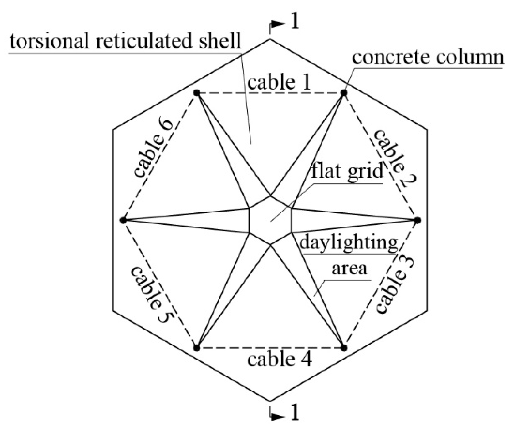
The case study of this paper is the gymnasium of Qingyuan City in the Guangdong Province, China, which is beautiful in shape and full of symmetrical beauty, as shown in
Figure 2. It can be seen from
Figure 3 and
Figure 4 that the upper part of the structure is composed of six torsional reticulated shells, which are connected with the hexagonal three-dimensional flat grid and the daylighting areas. The torsional reticulated shell is saddle shaped with negative Gaussian curvature, which can increase the stiffness while obtaining beautiful shape. The lower part of the structure is composed of six reinforced concrete columns. Different from the single-layer reticulated shell, the structure studied in this paper is a double-layer reticulated shell structure, in which all the connecting nodes of the members are hinged, as shown in
Figure 5. The area of the building is 5450 m
2. The diagonal span of the structure is 68,418 m, the cantilever is 12,615 m, and the structure height is 2.8 m.
The structural members are selected from the following sections: solid round steel rods with an equivalent size of 80 mm of prestressed cable, with a standard value of tensile strength of 1870 MPa; the dimensions of the roof steel pipes are: 60 mm × 3.5 mm, 68 mm × 3.5 mm, 76 mm × 3.5 mm, 83 mm × 3.5 mm, 89 mm × 3.5 mm, 95 mm × 3.5 mm, 102 mm × 3.5 mm, 114 mm × 4 mm, 121 mm × 4 mm, 133 mm × 4 mm, 140 mm × 4.5 mm, 152 mm × 4.5 mm, 168 mm × 4.5 mm, 180 mm × 5 mm, 194 mm × 5 mm, 203 mm × 6 mm, 219 mm × 6 mm, 219 mm × 8 mm, 245 mm × 6.5 mm, 273 mm × 6.5 mm, 299 mm × 7.5 mm, 351 mm × 8.0 mm, the steel is Q345; the cross-sectional size of the concrete column is 1200 mm × 1200 mm. SAP2000 is used to establish the model, and the version of software used in this paper is SAP2000 17.3. Rubber bearings are adopted at the connection of the upper roof and lower columns. The plane size of the rubber bearing is 500 mm × 750 mm, with a total thickness of 67 mm. The rubber bearing is simulated as a spring element with an effective stiffness of 7780 kN/m, and an infinite vertical stiffness.
3.2. Sensitive Areas Analysis of the Structure
We define as sensitive areas the weak parts of the structure, with the key members or nodes of the structure that are located in those areas. The sensitive areas are determined by the regions with a larger eigenvalue buckling response. The eigenvalue buckling analysis of the structure was carried out, and the first four modes were selected, as shown in
Figure 6. F. Fu et al. [
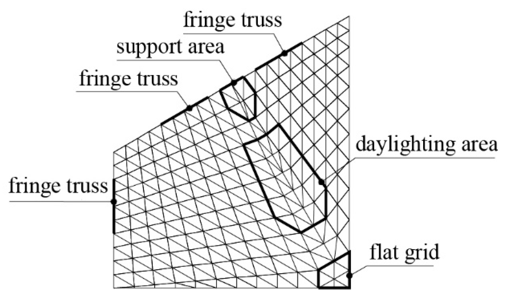
27] studied the progressive collapse performance of a double-layer space truss structure and concluded that the members at the supports are most critical. Hence, we considered the vicinity of the supports also as sensitive areas. Because of its symmetric structure, according to the first four eigenvalue buckling modes and support areas, the sensitive areas of the structure can be represented by one quarter of it, as shown in
Figure 7.
It can be seen from
Figure 7 that the sensitive areas are located in the support area, in the daylighting area, in the flat grid area, and in the fringe truss. Because the high redundancy of the long-span prestressed the double-layer composite torsion lattice shell, the removal of a single key member has a minor impact on it. To fully understand the failure mechanism of the structure, its damages after removing the nodes were investigated with the removed nodes that were located in the defined sensitive areas.
3.3. Simulation of Failure Nodes
When studying the progressive collapse of structures, it is necessary to consider their dynamic response. In particular, the dynamic load comes from the structural vibration caused by the sudden failure of members or nodes. In this paper, the equivalent load transient unloading method was used to analyze the progressive collapse dynamic time history of the LSPDLCTRS.
The main analysis steps of the equivalent load transient unloading method are shown in
Figure 8. Assuming the sudden failure of the node N under the action of unexpected loads, the members connected to the node were removed. Firstly, the inner forces P
1, P
2 and P
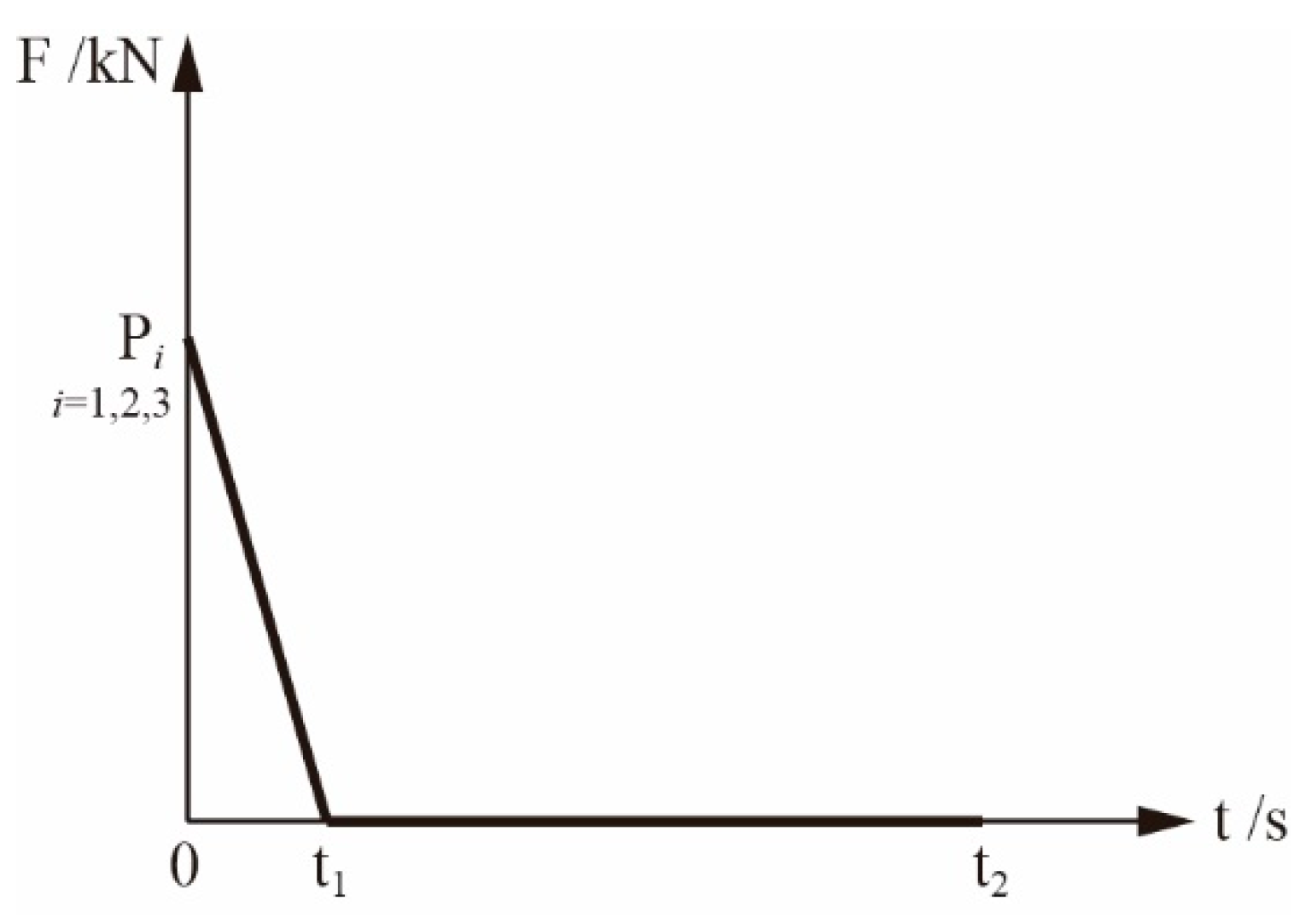
3 of the middle three members under the static load q were solved, and then the inner forces were reacted on the structure. Secondly, the failure process of the three members was transformed into the unloading process of loads P
1, P
2 and P
3 with time, thus defining the time history analysis curve shown in
Figure 9. In
Figure 9, t
1 represents the failure time of the removed member, which is generally no greater than 0.1T. T is the basic period of the remaining structure. t
2 represents the time of structural vibration stabilization. Finally, in the dynamic time history analysis, the load q was applied in the structure, and the loads P
1, P
2 and P
3 were applied, according to
Figure 9, while the residual of the structure was forced to vibrate under the loads.
The simulation method of node failure was introduced, which can be applied to the study of progressive collapse of the LSPDLCTRS. The load combination of 1.0DL + 0.25LL was adopted in the progressive collapse analysis. DL is the dead load and LL is the live load. The dead load (DL) includes the surface load, the bridle path of the lower chord, and the suspension load of the lower chord, which are 1 kN/m2, 0.35 kN/m2 and 0.5 kN/m2, respectively. The live load (LL) is 0.5 kN/m2. In this paper, t1 is 0.1 s and t2 is 25 s.
3.4. The Criterion of Structural Failure
Based on multiple responses and deformation energy, Nie et al. [
28] quantified the different damage states of long-span spatial structures under earthquake action. Zhang [
29] et al. used exponential strain energy density and maximum nodal displacement to classify the damage levels of long-span spatial structures. They divided the damage of long-span spatial structures into five damage levels: basic intact, slight damage, medium damage, severe damage, and collapse [
28,
29]. In this paper, we also divided the structural failure into five damage levels. Based on the dynamic damage index
D of Formula (1),
D = 0.2,
D = 0.4,
D = 0.7, and
D = 1.0 were selected as the boundary values of basic intact, slight damage, medium damage, severe damage, and progressive collapse. The corresponding damage levels were I, II, III, IV, V. When 0 ≤
D < 0.2, the components of the structure were almost in the elastic stage with a small displacement, which did not cause damages to structural elements and equipments, and no repair would be needed after a disaster. When 0.2 ≤
D < 0.4, a small number of components of the structure entered into a plastic stage, still not causing permanent damages and having a not prohibitive repair cost. When 0.4 ≤
D < 0.7, a certain number of components entered into their plastic stage, with the structure experiencing a certain degree of damage. The large displacement encountered by the structure caused a certain degree of damage to the water and electric systems, and to other equipment with a high repair cost after the disaster. When 0.7 ≤
D < 1.0, more components encoutered plastic deformations, thus causing serious damage. The displacement of the structure was very large; the water and electric systems, and other equipments would be seriously damaged, and the repair cost would be very high. When 1.0 ≤
D, the structure completely lost its bearing capacity and finally collapsed.
3.5. Intact Structure Analysis
The arc length method was used to analyze the intact LSPDLCTRS, and the static maximum displacement and the ultimate total reaction force of suppports of the structure were obtained, as shown in
Figure 10. The initial displacement of the structure was positive because the structure moved upward after the prestress was applied, as shown at point O. After the load of 1.0DL + 0.25LL was applied to the structure, the displacement started to increase in the opposite direction and became a negative value. Point P represents the ultimate value of the reaction force
of the structural supports, and the value is 32,259 kN. The maximum displacement of the structure is at point Q, and the value is −1424 mm.
3.6. Remove Sensitive Areas Nodes
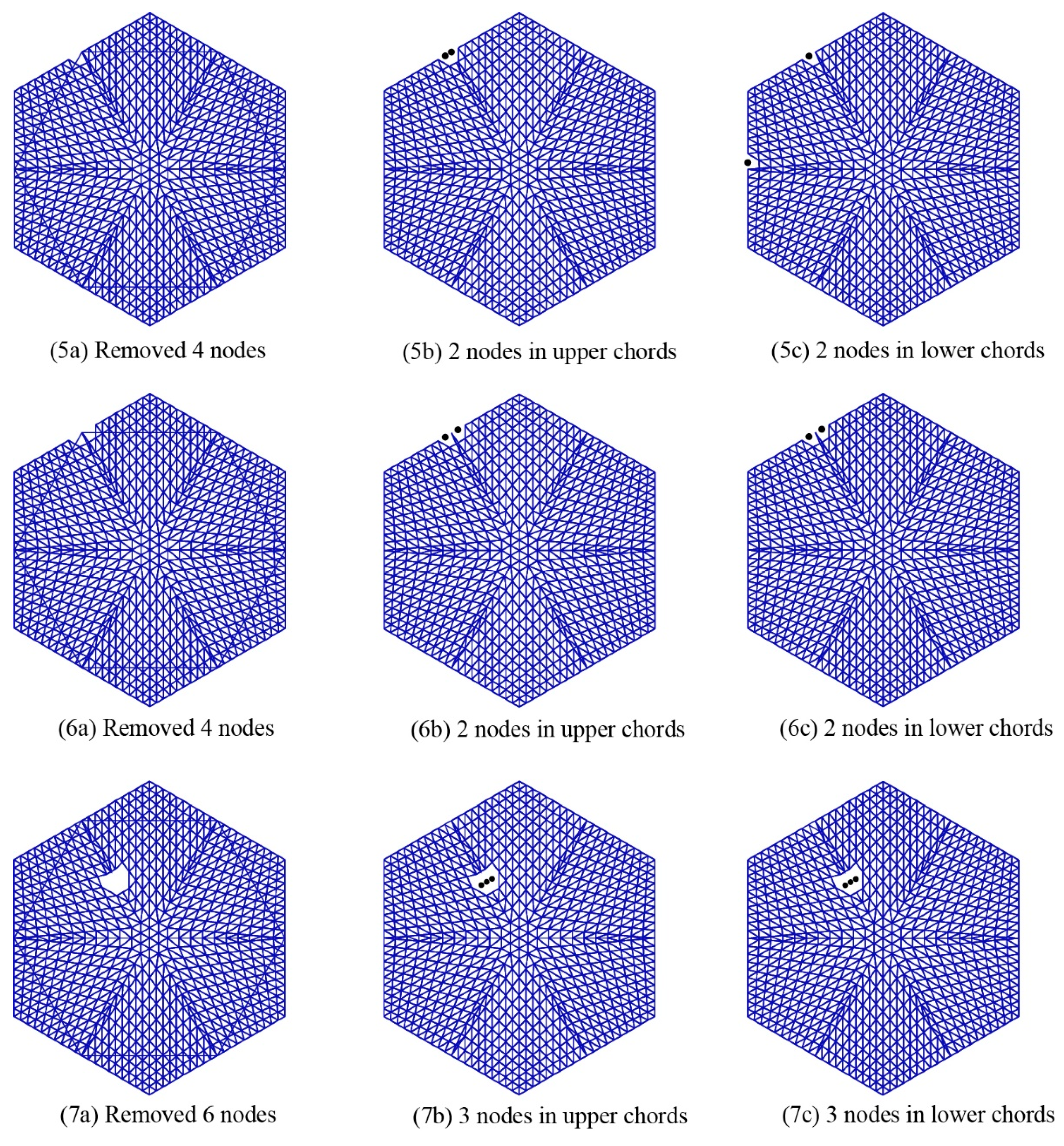
In order to comprehensively analyze the influence of node failures on the overall structure, several nodes in the sensitive areas in
Figure 7 were removed, including 2, 3, 4, and 6 nodes, as shown in
Figure 11. Since the structure is a double-layer structure, to better understand the location of removed nodes, the upper chord layer and the lower chord layer were used to show the specific location of the removed nodes. For example, two nodes were removed in the grid area in
Figure 11(1a), with the black solid dots in
Figure 11(1b,c) that indicate the specific removed nodes.
The nodes removed in
Figure 11 include sensitive areas, such as the support area, the daylighting area, the flat grid area, and the fringe truss area. The equivalent load transient unloading method, based on dynamic time history analysis was used to analyze the residual structure after the removal of the nodes. The ratio between the stress of structural member and the yield stress of material is defined as the stress ratio. The upper limit of the stress ratio of the members was set to 1.0. In the software of SAP2000, the stress ratio of each member in the structure was calculated and displayed. If the stress ratio was greater than 1.0, the components fell into their plastic deformation stage. The dynamic damage index
D of the structure was calculated according to formula (1), and the results are shown in
Table 1.
According to the value of the dynamic damage index
D, the damage levels of the structure with the different nodes removed can be classified as in
Table 1. The latter shows that the structures of
Figure 11(1a,2a,4a) and
Figure 11(7a) are at a basic intact level I. The structure of
Figure 11(3a) is at a medium damaged level Ⅲ. The structure of
Figure 11(5a) is at a severe damaged level Ⅲ. The structure of
Figure 11(6a) is at a progressively collapsed level Ⅴ.
In the distribution of the structural plastic hinges, B→IO→LS→CP→C→D→E indicates that the development degree is from low to high. Points B, C, D and E represent the yield, ultimate strength, residual strength and failure of member, respectively. Points IO, LS and CP represent the capacity level of the plastic hinge, corresponding to Immediate Occupancy (IO), Life Safety (LS) and Performance Levels of Collapse Prevention (CP). These points are reflected in the structure by different colors. The structure of
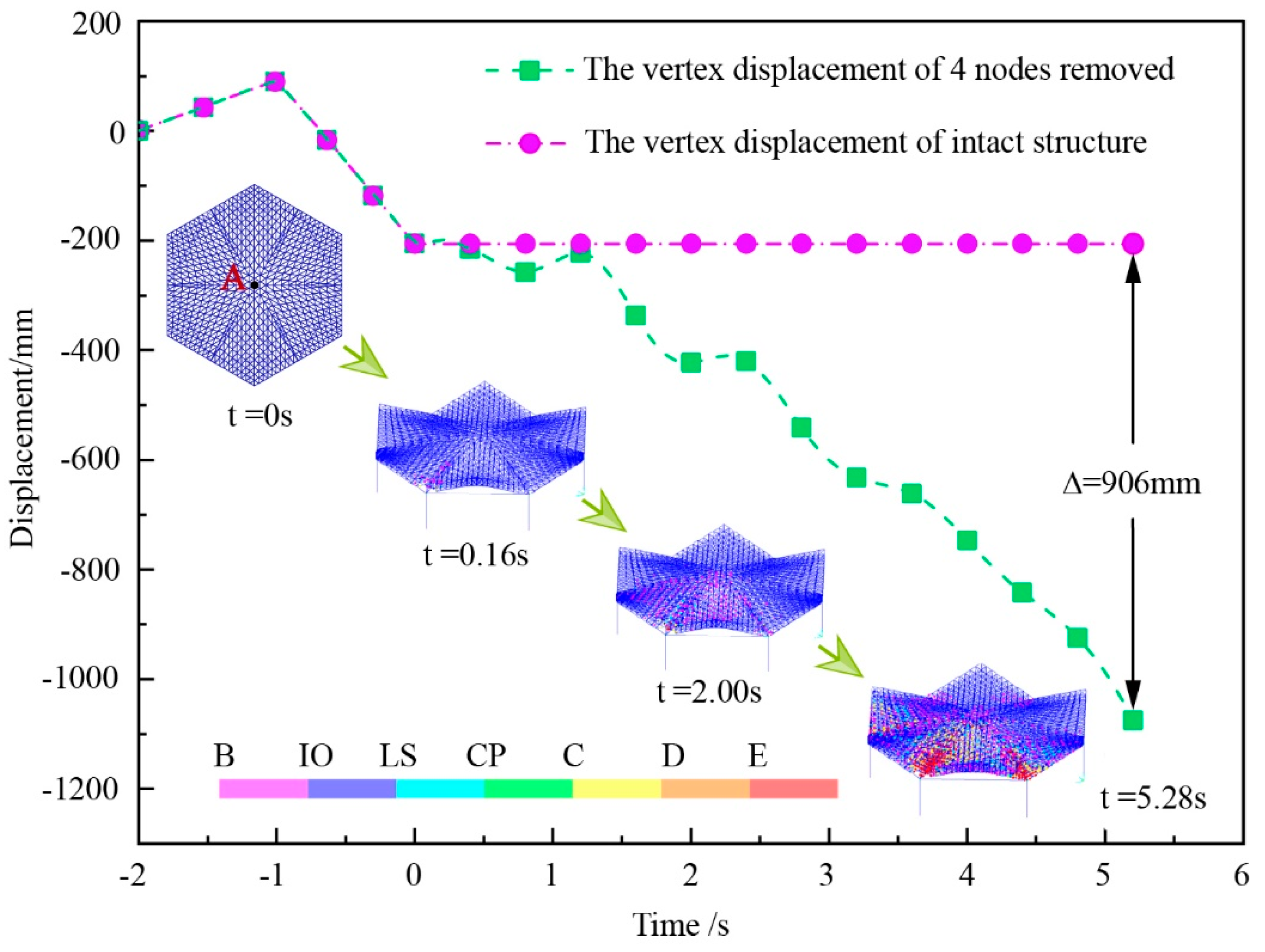
Figure 11(6a) was specifically analyzed and compared with the intact structure. The displacement–time curve of vertex A of the intact structure and the structure of
Figure 11(6a) are shown in
Figure 12. As the vibration continued, the difference between the vertex displacements of the two structures became larger and larger. At 5.28 s, the maximum displacement of 906 mm was reached, while the vertex displacement of the structure of
Figure 11(6a) was −1111 mm, and the displacement of the intact structure was −205 mm.
Figure 12 shows the failure process of the structure described in
Figure 11(6a). The plastic hinges first appeared near the support of the removed nodes and then developed outward. The two supports adjacent to the removed nodes encountered serious damages because the load of the support of the removed nodes decreased, thus leading the reduced part to be dragged by the two adjacent supports. A large number of members whose stress ratios exceeded 1.0 can be observed. The number of upper chord layers was 790, the number of web member layers was 524, and the number of lower chord layers was 719. The cumulative plastic energy dissipation increased, leading to a final energy of 98,052,095 J. The maximum displacement of the structure was −10,482 mm. The dynamic damage index
D was 9.459. The structure of
Figure 11(6a) encountered a progressive collapse.
4. Construction and Design of the Sleeve Structure
The sleeve structure was composed of an inner core and a sleeve with a gap. The length of the sleeve was slightly smaller than that of the inner core, as shown in
Figure 13a. When the inner core was under pressure, the sleeve mainly provided lateral restraint for the core and protected it from unexpected loads. High-order buckling modes can appear in the inner core to improve the load-bearing capacity of the member. Through the point contact or line contact between the core and the sleeve, the stress of the inner core under the restraint of the flexible sleeve reached the yield stress. The part of the inner core extending out of the sleeve was the weak part of the sleeve structure. This part was prone to buckling, thus determining the decline in the inner core bearing capacity. The structure of
Figure 13a was adopted for the reinforcement of this part. The part of the core extending from the sleeve was reinforced with a circular stiffening ring that had a thickness not lower than the wall thickness of the inner core. The inner wall of the sleeve and the outer wall of the stiffening ring required a net of at least 2 mm gap. One end of the inner core and the sleeve was a sliding hinge support, as shown in
Figure 13a,b; the other end of the core and the sleeve had a fixed hinge support, as shown in
Figure 13a,c. With this configuration, the inner core bore all the external load, and the sleeve could only resist the bending of the inner core. The arrangement of the sleeve structure in the long-span space structure was connected by the hinge of the inner core and the structure. The size and relevant design parameters of the sleeves were calculated according to the literature [
19,
30], as shown in
Table 2. The steel pipe number in the table indicates the members with sleeves that are required to be arranged in the structure—namely inner cores. The stress of these inner cores can reach the yield stress. The dimension specifications and lengths are listed in
Table 2. The sleeve sizes are the specification of the round steel pipes added on the outside of these inner cores. The sleeve and the steel pipe in the original structure together constitute the sleeve structure.
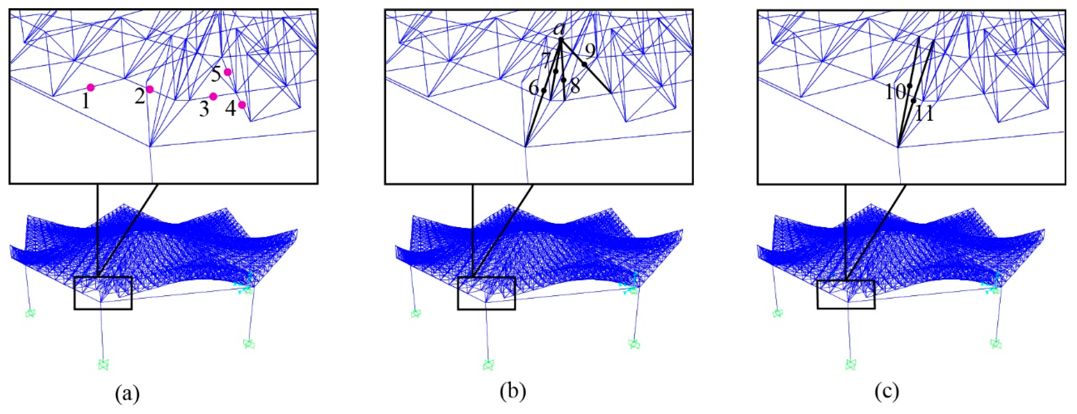
6. Control of Sleeve Structure to Medium Damage
The model described in this section is the structure of
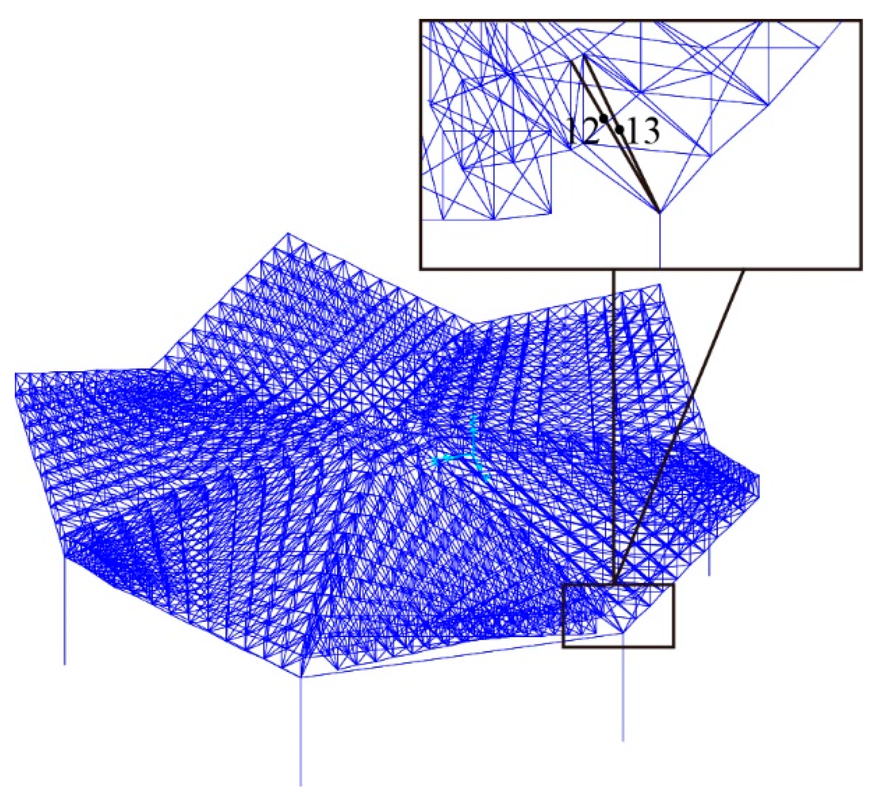
Figure 11(5a), with medium damage. According to the above sleeve structure arrangement principles, the sleeves should be arranged at the position with the maximum force in the structure. In the structure of
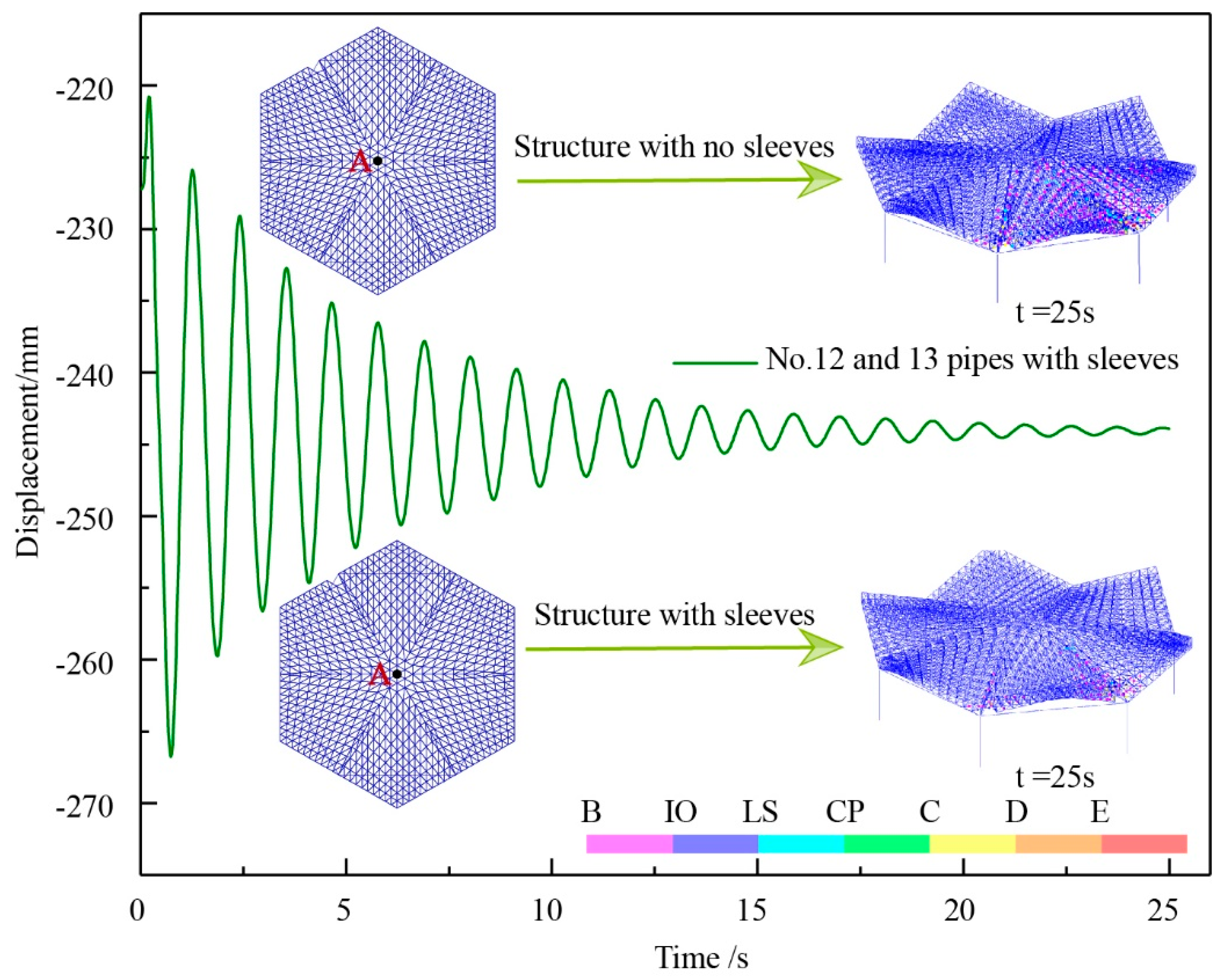
Figure 11(5a), the sleeves are arranged for members 12 and 13 with the maximum force, as shown in
Figure 17.
It can be seen from
Table 5 that the number of members with over-limit stress ratio in the upper chord layer decreased from 149 to 31, the web member layer decreased from 50 to 22, the lower chord layers decreased from 147 to 56, the maximum displacement from −925 mm to −244 mm, and the cumulative plastic energy consumption from 7,073,455 J to 357,216 J. The dynamic damage index of the structure was reduced from 0.804 to 0.179. According to the dynamic damage index
D, it can deducted that the structure was basically intact after damage, with the damage being at level I.
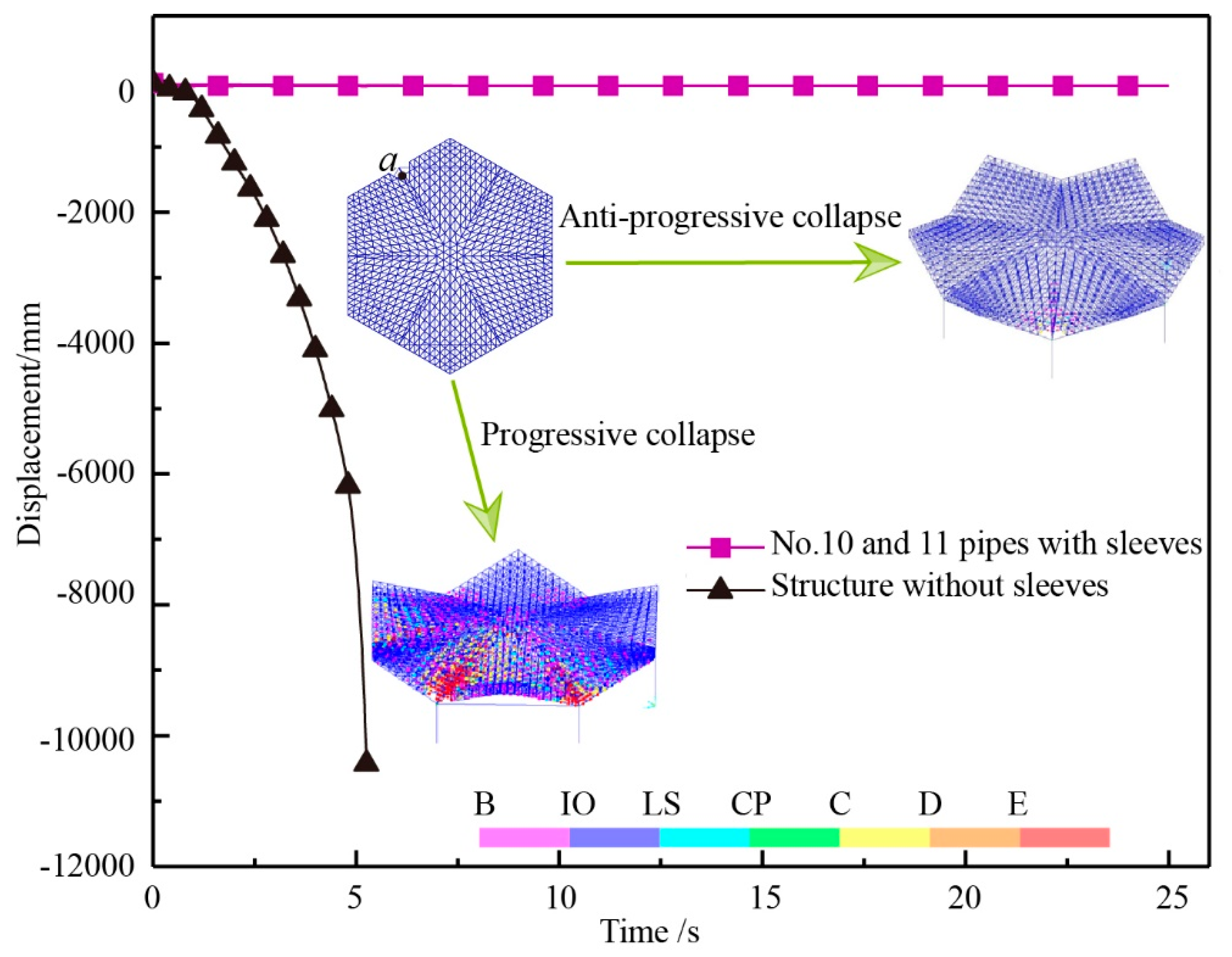
In
Figure 18, the displacement of vertex A was −244 mm, and after that the sleeves were arranged on the members 12 and 13. Through the comparison between the sleeve arrangement in the structure of
Figure 11(5) and that without sleeves arrangement, it can be seen that, after the sleeves were arranged, the range of plastic hinges was relatively small. This mainly occurs near the removed nodes, with the structure being slightly damaged. Contrarily, for the structure without sleeves, the plastic hinges appeared in a larger range, with the structure being in a basically intact after damage state.
From the above analysis, it can be seen that the sleeves were arranged in the members with the maximum force, thus reducing the damage of the structure from a severe damage level to a basic intact damage level.


