1. Introduction
Inertial propulsion drives belong to a promising field of research and have therefore gained the attention of scientists and engineers in recent decades. These mechanisms are multi-body systems with eccentric masses in motion, usually presenting symmetry on one or two axes to compensate undesired forces in the direction orthogonal to the displacement. Displacement is produced by a propulsion force developed as a reaction to the variable centrifugal forces which are acting on a number of masses rotating on an eccentric trajectory.
It is a huge controversy about the effectiveness of inertial force-based propulsion drives because they challenge Newton’s laws of motion [
1]. In a National Aeronautics and Space Administration (NASA) report [
2] anti-gravitational systems are considered to be impossible, but no discussion on specific inertial propulsion drives (IPDs) is made. In opposition, Allan Jr. wonders rhetorically: “Why does classical mechanics forbid inertial propulsion devices when they evidently do exist?” Thus, in his book [
3], he presents a series of working inertial propulsion devices [
4,
5,
6].
It is also shown that the inertial system proposed by Couloumbe [
7] is not linked to gravity and may work in space. While this IPD is not gravity-based, it does not fall under the “restrictions” formulated by Millis and Thomas [
2]. Numerous other patents are known [
8,
9,
10,
11,
12,
13,
14,
15,
16,
17,
18,
19,
20,
21,
22,
23,
24,
25]. Sadly, only a few of them exchange the stage of patent to the practical materialization. Here, the Dean Drive [
26], with applications in the construction of inertial pumps and vibration elevators [
1], or the Thornson Apparatus [
27], which was able to develop a velocity of 1.6 miles per hour installed on a canoe in a swimming pool, can be mentioned.
An example of a patent without practical materialization is the propulsion unit proposed by Booden [
9]. It converts the energy of two identical electromagnetically spinning assemblies of weights, which are rotating in opposite directions, in a unidirectional thrust. The invention relies on rotating elements with variable gyration radius around a center axis in order to provide an imbalance of centrifugal force to generate propulsion in a given direction.
Similarly, Cuff [
10] discloses a mechanism for varying the radius of rotation of a plurality of rotating weights and for selectively modifying the direction of the resultant unbalanced force generated by these rotating masses. More particularly, the device comprises of two commonly non- rotating circular cams, disposed eccentrically, which engage a pair of cam followers that are linked to connecting rods which are successively joined to the gyrating weights. The direction of the unbalanced resultant force can be adapted by simply rotating, in concordance, the two commonly non- rotating cams.
The propulsion apparatus suggested by Dobos [
11] includes a platform and a shaft placed perpendicularly on it. The shaft supports a disk which carries on the circumferential edge portion a plurality of reservoirs filled with liquid and spaced completely around the circumference of the disk. Each reservoir contains a buoyantly positioned hollow piston with a road which extends outwardly from the reservoir. An adaptable movable cam with a cam track is mounted on the shaft assembly—this is placed eccentrically relative to the axis of the shaft assembly. The piston rod ends are placed in opposition to the cam track. Thus, the movement of the pistons generates a relative displacement of the liquid in the reservoirs in response to the contact of the piston rods with the cam track, creating an unbalanced centrifugal force, which moves the platform in a preselected linear direction.
Another IPD using fluids for converting rotary motion into linear displacement was more recently proposed by Deschamplain [
21]. His motion imparting system contains a centrifuge with a chamber partially filled with a quantity of fluid. A motor imparts a rotary motion to the centrifuge, the water being moved outwardly under the action of centrifugal forces. During the rotation of the centrifuge, an object is at its exterior end positioned within the fluid and at its interior end positioned exterior of the fluid in the air. Parallel with the axis of the centrifuge, but laterally offset is placed a rod which is rotated by a driver with the same speed as the centrifuge. A coupling connects the rod with the object. The centrifugal forces which occur during the simultaneously rotation of the rod and centrifuge are converted to a linear force.
In addition, in a recent patent, Murray [
23] comes up with a mechanical force generator for converting the energy of centrifugal force in propulsion force by rotating a cage assembly around its longitudinal axis. Thus, the cage rotates secondary shafts which turn sets of eccentrics for generating a net force in a direction which is transversal on the rotation axis of the cage assembly. Two pairs of eccentrics turn such that for each 90° rotation of the carrier cage, the pairs of eccentrics have their mass centers located rather between an unbalanced and a balanced condition, but, at each quarter of complete rotation, one pair of eccentrics is every time generating a power stroke.
The effect of friction between the IPD and the external supporting surface was studied in [
28]. Like it was concluded in similar researches [
29,
30], it was found that friction is important for providing movement. Other authors [
31,
32] consider that IPD’s are able to produce displacement on frictionless supports or in space because reaction forces are not necessary.
Provatidis [
33] makes a critical review regarding the actual state-of-the-art of inertial devices capable to move the objects on which they are attached, concluding, same as Robertson and Webb [
34] that “the replacement of rockets by other advanced means is an ongoing procedure” and “the death of rocket science is only a matter of time.”
The aim of this paper is to present an IPD developed by the authors which is using two groups of rotating masses. Furthermore, the mathematical relations, deducted for the kinematic of these rotating masses are introduced, the analytical results being compared with the outcomes of simulation data obtained by involving a professional software. Three versions of trajectories for the rotating masses are considered, and the best solution in terms of displacement velocity and power consumption is proposed for the construction of the system. Finally, to validate the functionality of the system, the most efficient version is built and experimental proofs are carried out.
2. Description of the Proposed IPD
The propulsion of the device developed by the authors [
35] is based on producing a resultant centrifugal force for driving the assembly. As shown in
Figure 1, the multi-body system consists of two identical groups disposed symmetrical relative to the direction of displacement. Each group consists of 8 equal steel balls (1/1 ÷ 1/8) with radii of 5 mm, placed between two rotating plates (2/1 and 2/2), which are foreseen in radial direction with 8 hemispherical slots for guiding the steel balls. The trajectory of the balls is maintained by the inner bore of a retaining disk (3).
The retaining disk is designed in three constructive versions, as shown in
Figure A1 (see
Appendix A):
- -
Version 1: Inner bore with a radius of R1 = 41 mm and the center placed eccentric at a distance e = 20 mm, relative to the center of the slotted plates;
- -
Version 2: Inner bore consisting of a semicircle with a radius R2-1 = 44.6 mm, two straight portions tangent to the semicircle and an arc of radius R2-2 = 61 mm, concentric with the first radius semicircle;
- -
Version 3: Inner bore consisting of two semicircles with radii R3 = 41 mm and centers placed at a distance of e = 20 mm, which are connected by two straight portions tangent to the semicircles.
For rotating the two constructive groups with the same angular speed, but in opposite directions, two spur gears (4/1 and 4/2) with the same number of teeth are used. The gears are supported by the shafts (5/1 and 5/2), which are also driving the slotted plates (2/1 and 2/2). The longer shaft (5/1) is connected with the driving motor which rotates the assembly with a constant speed n = 1200 rot/min. The retaining disk (3) is locked on the base plate (6) of the system, which lies on four rubber rollers of 40 mm diameter and fixed axis.
Rotating the plates 2/1 and 2/2 with a constant angular velocity ω, on each of the 8 steel balls acts a centrifugal force. As the balls are forced to follow a circular trajectory, but with variable radii R
i(t), these centrifugal forces are variable in time and may be expressed in (1):
where:
Fci(t) [N]—centrifugal force acting on the balls;
m0 [kg]—mass of the balls;
ω [rad/s]—angular velocity of the rotating plates;
Ri(t)—trajectory radius of ball i.
The resultant of the centrifugal forces acting on the 8 steel balls produces the linear propulsion of the assembly.
3. Analytical Investigation of the Three Proposed Constructive Alternatives
In this study, the physical quantities which describe the kinematics of the system are calculated in regard with the three constructive alternatives of the retaining disk. Furthermore, the deduction of the analytical expressions for the displacement, velocity and acceleration of the steel balls is presented.
3.1. Version 1 of Retaining Disk: Cylindrical Bore Placed Eccentric Relative to the Center of the Slotted Plates
For finding the analytical expressions of the elements which characterize the kinematics of one of the balls, having the center in C
i, a Cartesian system denoted with xO
1y was attached to the center O
1 of the slotted plates (2/1 and 2/2). Furthermore, as shown in
Figure 2, the circle with radius R
1 and center in O
2, represents the inner bore of the retaining disk (3). As mentioned before, the retaining disk is placed eccentric, relative to the center of the slotted plates, at a distance
e.
Following the procedure described in detail in [
36,
37] and the notations from
Figure 2, the Cartesian coordinates and the trajectory radius of the center C
i may be written as in (2) and (3):
By deriving Equations (2) and (3), the components of the ball velocity are obtained as follows in (4) and (5):
Furthermore, deriving the expressions of the velocities, the components of the ball acceleration along the x and y axis are expressed as follows in (6) and (7):
3.2. Version 2 of Retaining Disk: Inner Bore Consisting of a Semicircle, a Circular Arc and Two Straight Portions
Similar to the previous case, a Cartesian system denoted with xOy was attached to the center O of the slotted plates (2/1 and 2/2). The inner bore of the retaining disk has at this constructive version a special design, consisting of a semicircle with center in O and radius R
2-1, a circular arc with radius R
2-2, concentric with the semicircle and two straight portions of length R
2-1, which are tangent to the semicircle (see
Figure 3).
Using the notations from
Figure 3, the Cartesian coordinates and the trajectory radius of the center Ci of a ball, may be written, depending on the position angle α, as follows in (8):
The components of the ball velocity v
x and v
y are obtained in (9) by deriving (8):
Correspondingly, the components of the ball acceleration a
x and a
y are obtained in (10) by deriving (9):
3.3. Version 3 of Retaining Disk: Inner Bore Consisting of Two Identical Semicircles with the Centres Located at a Distance “e” and Two Straight Portions Tangent to the Semicircles
For the analytical approach of this constructive version, the Cartesian system denoted with xOy was attached to the center O of the slotted plates. This time, the inner bore of the retaining disc consists of two equal semicircles of radius R
3. One of the centers of the semicircles is located in O, while the other is placed at the distance e in vertical direction. The two semicircles are connected by two vertical segments tangent to the semicircles (see
Figure 4).
Depending on the position angle α and using the notations from
Figure 4, the Cartesian coordinates of the center Ci of a ball, can be expressed in (11) and (12):
where in (13):
α* is the position angle of the inflection point, where the trajectory of the balls changes from circular to linear and vice versa.
In the same way, by deriving twice the expressions of the ball coordinates, the velocities and accelerations may be deducted as follows in (14)–(17):
4. Motion Simulation of the IPD
Like in our previous researches [
38,
39], the resources of the Motion module [
40] from SolidWorks (SW) program were used. SW Motion is a module powered by ADAMS technology, being a virtual prototyping tool for technicians involved in assessing the performance of their design
There are two equations which are governing the three dimensional (3D) motion of a rigid body in the Motion module. The first one is Newton’s second law of motion, which affirms that the sum of externally applied forces on a rigid body is equal to the rate of change of linear momentum P, as written in (18):
This equation for bodies with constant masses (m), simplifies to the more commonly known form (19):
with a for the acceleration of the body.
The second equation starts from the premise that the sum of the moments about the center of mass of a rigid body, due to external forces and couples, is equal to the rate of change of the angular momentum H of this body, which may be expressed in (20):
The program applies the modified Newton–Raphson iteration method in several time steps. Setting very small time steps, the program is able to predict the position of parts at the next time step, starting from the initial conditions or the precedent time step.
Following steps were employed in the motion study:
- ○
Design of the components shown in
Figure 1b;
- ○
Generation of the assembly;
- ○
Specification of the speed for the rotary motor (1200 min−1);
- ○
Specification of gravity;
- ○
Specification of solid body contacts;
- ○
Specification of the mates.
To specify the rotary motor parameters, the motor icon was chosen, while the inner cylindrical face of the slotted plates (2/1 and 2/2) was selected, together with constant speed from the motor type list.
Furthermore, selecting the gravity icon, axis Z as direction of action and the value of 9806.65 mm/s2, the gravitational forces acting on the mechanism were simulated. Finally, the mates between parts were applied in the motion study between the components of the assembly.
A Solid Body Contact 1 was imposed between the first group, defined as the left situated balls (1/1 ÷ 1/8) and the second group, defined as the left situated retaining disk (3) and the base plate (6) generated as a single part together with the left rotating plates (2/1 and 2/2).
Next, a Solid Body Contact 2 was imposed between the first group, defined as the right situated balls (1/1 ÷ 1/8) and the second group, defined as the right situated retaining disk (3) and the base plate (6) generated as a single part together with the left rotating plates (2/1 and 2/2).
For both of Solid Body Contacts one type of material applicable to touching faces during contact were imposed. As the retaining disks were manufactured by 3D printing, from polylactide (PLA) filament, the selected material combination was acrylic with steel. For every material combination the elastic properties of the materials involved in contact phenomenon are selected automatically by SolidWorks Motion.
The simulation was performed without considering any friction, because we intended to compare the simulation outcomes with the analytical results, where, as simplifying hypothesis for constructing the mathematical model, the friction was neglected. It’s obvious that the friction is influencing the results, but we have to mention that in this case we are dealing with rolling friction, which may be neglected, in accordance with the most similar mathematical models.
The analysis time of the study was imposed to 0.2 s. Within this time, at a speed of the slotted plates n = 1200 rot/min, they rotating 4 times, the duration of a complete rotation being 0.05 s. Furthermore, for the motion analysis were set 1440 frames per second, namely 72 frames for one rotation, meaning that the results were obtained at every 5° indexing of the slotted plates. Moreover, during the simulation was used a “precise contact” with an accuracy of 0.0001, while the contact resolution was set to medium.
5. Results and Discussion
In the first stage of the simulations, the coordinates, velocities and accelerations of a ball where computed for a complete rotation of the slotted plates. Furthermore, the simulation outcomes were examined in contrast with the analytical calculations accomplished by using Equations (2)–(17). The obtained results regarding the physical quantities which describe the kinematics of the ball (x, y, v
x, v
y, a
x and a
y) as functions of the rotation angle α are presented, for the three constructive versions of the retaining disk, in
Figure A2,
Figure A3 and
Figure A4 (see
Appendix A).
As it can be observed from
Figure A2 and
Figure A3, in the case of the displacements and velocities, the outcomes obtained by analytical calculation and SW simulation are almost identical, for all three constructive variants of the retaining disk. This confirms first that the analytical relations are correct and, second that the virtual model constructed in SW corresponds with the reality.
A deviation between the analytical and simulation approach can be observed at the retaining disk having the inner bore consisting of a semicircle, a circular arc and two straight portions (Version 2), the highest differences being observed around the points where the ball is changing the trajectory from circular to linear and vice versa.
Regarding the differences between the accelerations that are observed in
Figure A4, these may be justified by the fact that in the simulation the effect of the collision between the ball and the inner bore of the retaining disk is taken into consideration, phenomenon which we neglect at the analytical calculation. Each collision generates an impact force which affects the acceleration values achieved by simulation.
Furthermore, the displacement and velocity of the whole system was simulated.
Figure 5 depicts the displacements of the system for the three investigated versions of the retaining disk. As it can be noticed, immediately after starting the turning of the slotted plates, because of the high inertia, the systems get an impulse, but after the first turn (T > 0.05 s), they become steady and the displacements grow linearly.
Within the simulation time, the highest displacement (y = 0.22 mm) was shown by Version 1 of the retaining disk, the other two variants getting similar results. Note that the system modeled by Version 3 has, except for the start phase, a negative displacement up to the fourth rotation (t = 0.17 s).
In terms of velocities, the comparison between the three constructive alternatives of the retaining disk is depicted in
Figure 6.
Figure 6a shows the variation of the velocities during the whole simulation time (0.2 s), while
Figure 6b illustrates the average velocities within the last complete rotation of the slotted plates. As it can be observed, the highest average velocity of the system is obtained at Version 1 (0.586 mm/s), while for Versions 2 and 3 the simulation highlighted speeds of 0.127 mm/s and 0.270 mm/s respectively.
Another benefit of the Motion module from SolidWorks is that it furnishes very easy information regarding the power consumption for driving the system, data which would be harder to attain by an analytical approach. Relevant information on this issue is shown in
Figure 7, during the last rotation of the system and for the three investigated alternatives of the retaining disk.
The theoretical background on which the computation of the power consumption in the Motion module is based starts from the well-known relation of the output power of a motor, which is the product of the torque (T) that the motor generates and the angular velocity (ω) of its output shaft. Moreover, applying Newton’s Second Law for rotating bodies, the torque generated by the motor is equal with the product between the mass moments of inertia (I) of the body which is rotated about the axis of the motor and the angular acceleration (α) of this body.
As it can be observed, after the system became stable, the power consumption graph shows a few peaks, the most relevant one being experienced at Version 2. Version 3 shows also some power consumption peaks and Version 1 is the most stable in terms of power variation, requesting in average the smallest power for driving the system.
Summarizing, the most advantageous version of the IPD, in terms of velocities, displacements and power consumption, is Version 1 of the retaining ring.
6. Experimental Proof of the Concept
The obtained results encouraged the authors to build a prototype of the IPD [
41]. For this, the additive manufacturing, using 3D printing was involved for producing the slotted disks (2/1 and 2/2), the gears (4/1 and 4/2), the retaining disks (3) and the two bearing covers which are sustaining the driving shafts.
Figure 8 shows some details of these parts and the printer.
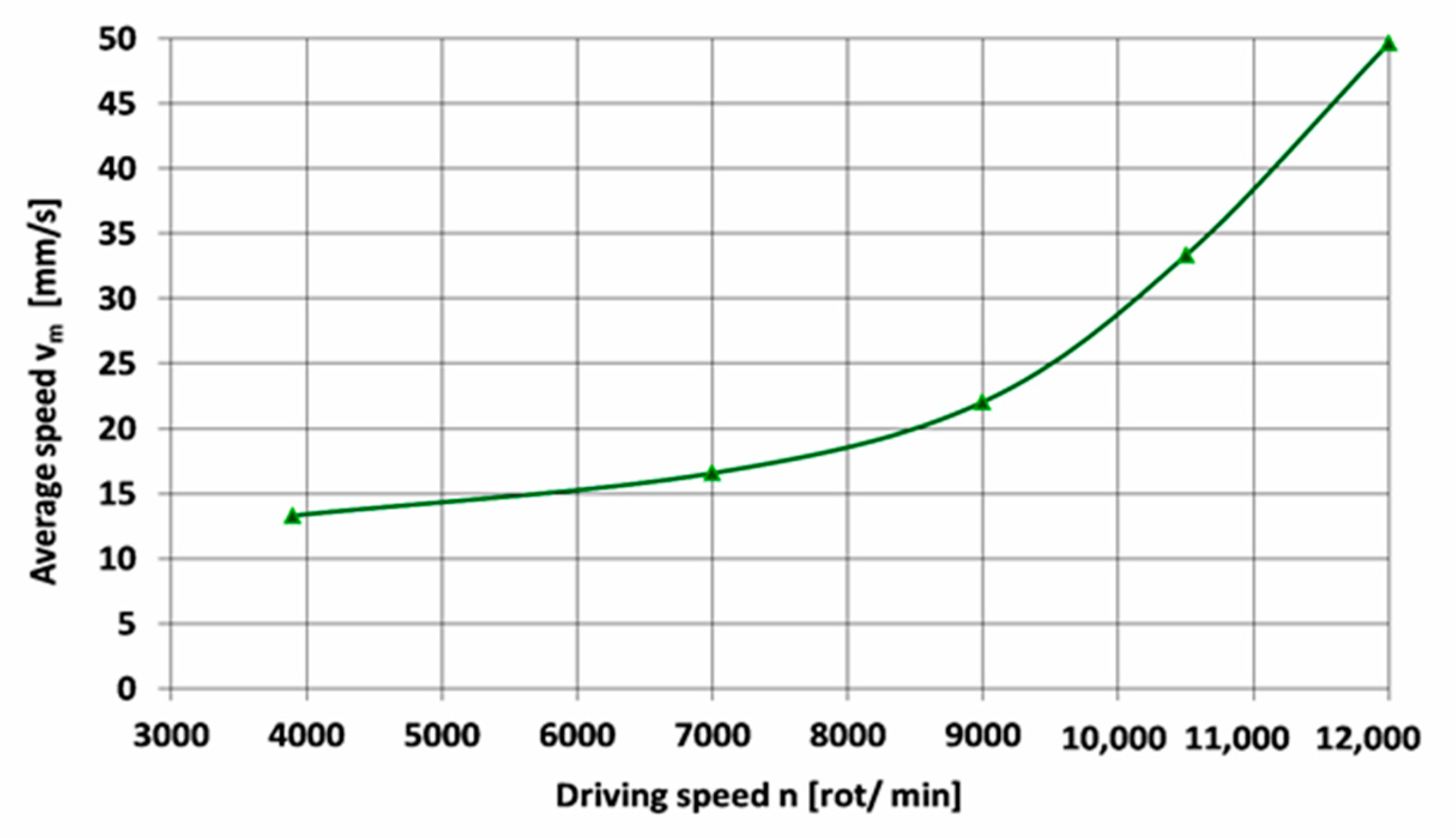
For driving the system, an angle grinder with a power of 1010 W and five steps of speed (3900, 7000, 9000, 10,500 and 12,000 rpm) was employed.
The tests aimed to determine experimentally the displacement speed of the IPD at the upper mentioned driving speeds. Therefore, the device covered a distance of 200 mm, the required traveling time being measured. For each driving speed step, three timings were made, the average displacement speed being calculated as the ratio between the distance traveled and the average travel time.
Figure 9 shows a picture of the experimental setup, while
Table 1 presents the measurement results and the calculated average displacement speed.
It is obvious that the displacement speed grows with the increase of the driving speed. Thus, by amplifying the driving speed 3.08 times (from 3900 to 12,000 rpm), the average speed increases 3.73 times (from 13.31 to 49.63 mm/s). To have a better image regarding the influence of the driving speed on the average displacement speed of the IPD,
Figure 10 provides a graphical representation of this interdependence.
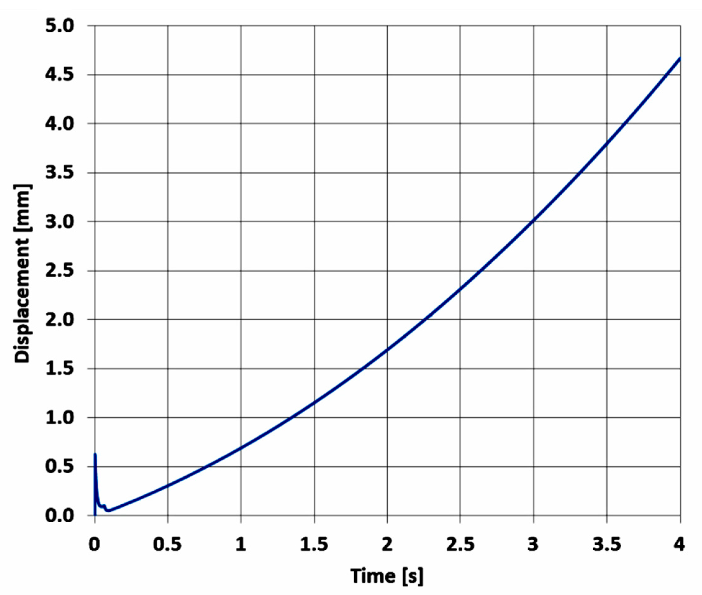
Since the optimization of the IPD design was performed by numerical simulation at a speed lower than the speed at which the experimental measurements were done, the numerical simulation using Motion module from SW was redone at a driving speed of 3900 rpm. In order to maintain reasonable computation duration, the analysis time for the motion study was set to 4 s. The simulation outcomes regarding the displacement of the system are shown graphically in
Figure 11.
As one can observe, the behavior of the IPD is identical to that shown during the simulation presented in Chapter 5. This means that, immediately after the system starts to be driven, its movement increases sharply, and then decreases, just as suddenly, after which, the distance traveled by the device increases smoothly. At the end of the analysis time, the IPD has covered a distance of 4.67 mm. The distances traveled by the IPD after intermediate durations of 2, 2.5, 3 and 3.5 s are shown in
Table 2.
For the experimental tests, the device displacements after durations of 2, 3 and 4 s, respectively, were measured with a dial gauge. For each of the above mentioned durations, three distance measurements were made, the average distance of the three measurements being compared with the simulation outcomes.
Table 3 presents the measurement results, in opposition to the simulation outcomes and the percentage differences between the two approaches.
As it can be observed, there is a good correlation between the simulation and the experimental results, with maximum differences of 10%. This confirms, on the one hand, that the experiments were set correctly and, on the other hand, that the 3D model and numerical simulation were performed correctly.
As the ability of the IPD concept to develop unidirectional movement has been also proven by experimental test, the future researches are aiming to study the efficiency of the drive and the influence of external factors, such as friction between wheels and ground, in order to improve the construction and to optimize the kinematic and dynamic behavior.
7. Conclusions
In this paper, a multibody inertial propulsion drive with symmetrically placed balls rotating on eccentric trajectories was presented. In this context, three versions of trajectories for the rotating masses of the IPD were investigated. Starting from the coordinate equations of the balls, their velocities and accelerations were analytically deducted, for each of the constructive version. Furthermore, using the Motion module from SolidWorks (SW), a kinematic and dynamic simulation was completed, the outcomes being examined in contrast with the analytical results. It was observed that in case of the displacements and velocities, the results obtained by the two approaches are almost identical, for all the three constructive variants of the retaining disk. The bigger differences in matter of accelerations between simulation and the analytic procedure were explained by the fact that in the analytical approach the collisions between the balls and the inner bore of the retaining disk were neglected. Furthermore, the 5° step with which the motion analysis was performed, in order to have a reasonable duration of the simulation, could be another reason for these differences.
Moreover, the kinematic and dynamic performances of the three constructive versions were compared. In terms of displacements, Version 1 ensures a 5, respective 10 times longer displacement within the simulation time, compared to Versions 2 and 3. Regarding velocities, the IPD equipped with Version 1 of the retaining disk is in average with 4.61, respective 2.17 faster than the IPD’s foreseen with retaining disks constructed in Version 2 and 3 respectively. Moreover, Version 1 requires by far the smallest power consumption for driving the system. Therefore, it was concluded that the variant of retaining disk with cylindrical bore placed eccentric relative to the center of the slotted plates (Version 1) is the most advantageous version of the IPD regarding displacement, velocity and power consumption.
For proofing the ability of the device to generate linear movement, experimental tests were also performed. Thus, operating the system with five different driving speeds, it was obvious that the IPD’s average displacement speed grows with the increase of the driver speed.
Finally, the present study confirms that the IPD developed by the authors is functional and capable to generate unidirectional linear movement, being especially suitable for spaces where the gravity is missing.


