1. Introduction
Hollow columns are an excellent functional form as Galileo first reported in the 17th Century [
1]. They exhibit superior mechanical stability and strength against axial compression, bending, and torsion compared to solid columns with the same cross-sectional area. This mechanical advantage is mainly due to the improved cross-sectional performance caused by the presence of the internal cavity. In the case of hollow columns, the constituent material is absent in the cavity; instead, it is distributed far from the columnar axis. This material distribution increases the buckling resistance and bending stiffness of the column and reduces the maximum bending stress at the outer edges. In addition to increased rigidity and strength, hollow columns are also superior to solid columns in that they are lightweight and material-saving. In this way, hollow cylinders and prisms have been used for a long time as building members and machine parts because they have excellent cross-sectional performance and are economical (require little material).
Besides artificial structures, the culms, stems, and branches of some wild plants have an excellent functional form with hollowness. Bamboo is a salient example of such plants [
2,
3], native to warm and moist tropical regions in the world [
4,
5]. From a structural mechanics perspective, bamboo culms are considered long hollow cylinders with a slightly thicker base and thinner tips [
6]. This tapered configuration improves rigidity against bending forces caused by cross winds compared to hollow cylinders of uniform diameter. Furthermore, due to its hollow nature, bamboo culms are lighter than solid columns with the same culm diameter and therefore can grow faster with a small amount of photosynthates [
7,
8]. This fast-growing feature allows bamboo to compete favorably for survival with other plants. These facts prove that bamboo is a plant with an excellent functional structure that combines light weight, high stability, and material saving.
Let us remind that many species of bamboo are endowed with circular cross-sections. Nevertheless, certain species of bamboo, like
Chimonobambusa quadrangularis (Franceschi) Makino, have a square-like cross-section along the whole length of the culms [
9].
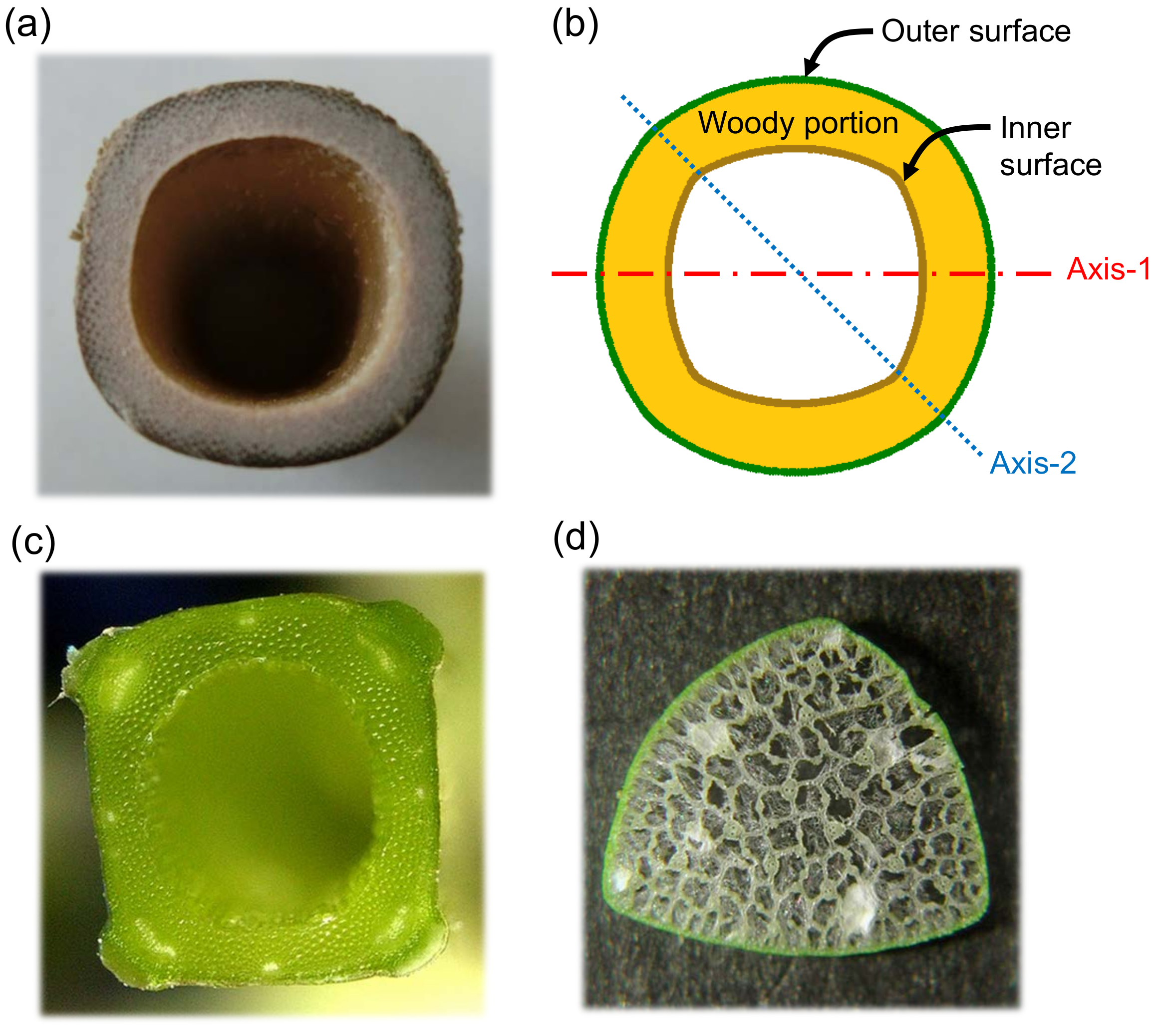
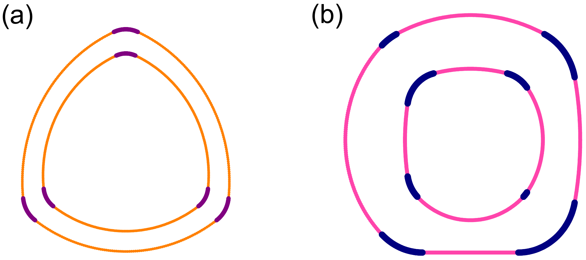
Figure 1a shows the cross-section of the square bamboo [
10]. It is typically two or three centimeters in outer diameter [
10], having a square cross-section with rounded sides and filleted corners, as schematically illustrated by
Figure 1b. Besides the square bamboo, many plants are known to have polygon-shaped cross-sections in their stems or branches [
11]. A mint (
Lamiaceae) showing a square stem and a papyrus (
Cyperus microiria) showing a triangular stem are cases in point; see
Figure 1c,d. From the point of view of plant physiology, we speculate that the reason why these plants have a polygonal cross-section is that this may promote the formation of phyllotaxis and help identify the location of leaf formation. On the other hand, the choice of polygonal shapes instead of a simple circular annulus is expected to provide a feasible shift in their cross-sectional performance, though no quantitative examination on this issue has been found. Moreover, the polygonal cross-section of the plant has significantly rounded sides and vertices, unlike the exact regular polygon, which consists of straight line segments and sharp vertices. Therefore, the simple mathematical formulas established in the engineering field cannot be applied to the evaluation of sectional performance. To address this issue, it is essential to develop a theoretical model that describes plant-like polygons with rounded sides and filleted corners.
In the present work, we create a mathematical model that describes the rounded squares observed in the cross-section of a square bamboo. By varying the parameters, this model is broadly applicable to polygonal hollow (and solid) prism and can also include triangular, pentagonal, and hexagonal prisms. This model is used to analyze the cross-sectional performance of hollow square prisms. Particular emphasis is placed on the section modulus and radius of gyration of the area, which generally determine the mechanical stability and strength of the prism.
2. Modeling a Rounded Square with Filleted Corners
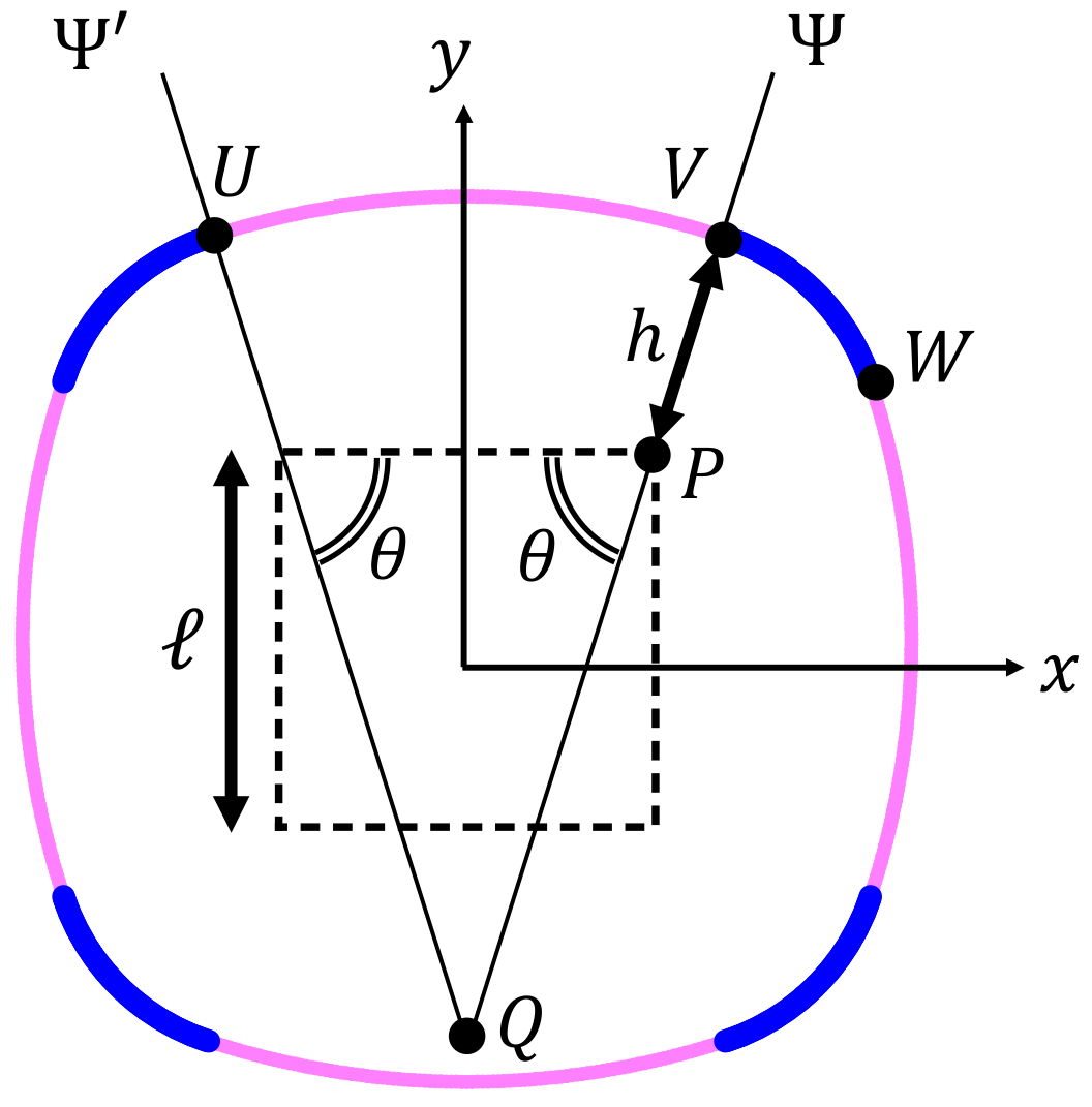
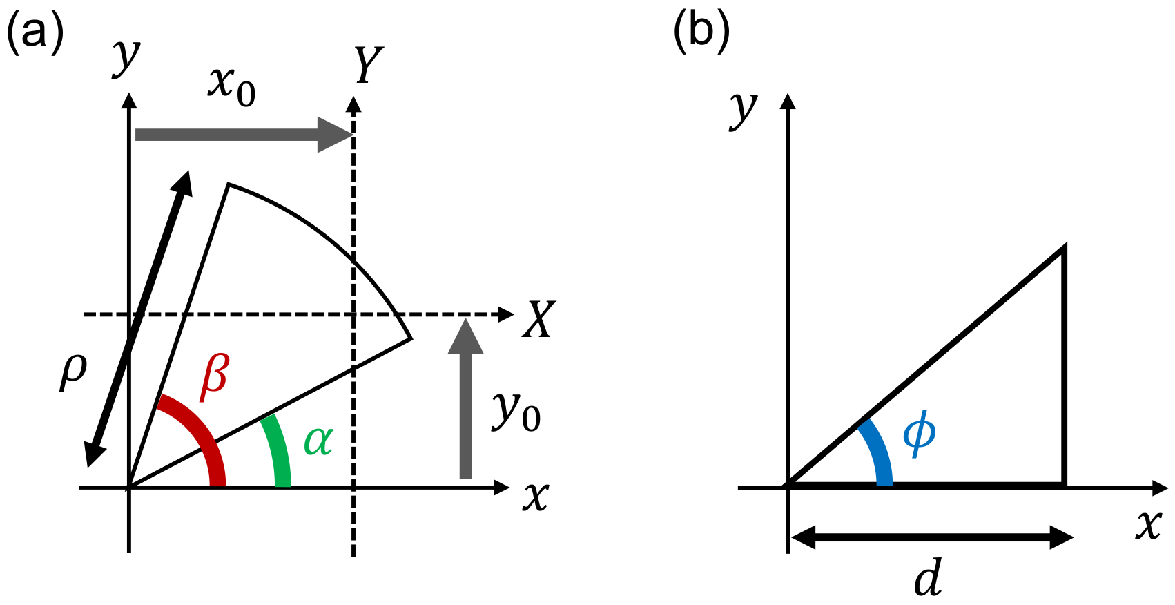
We propose a quadrangular prismatic model whose shape is similar to that of square bamboo.
Figure 2 illustrates the drawing of the cross-section, which possesses the four-fold symmetry composed of four long circular arcs (colored in magenta) and four short circular arcs (blue). The cross-sectional shape is uniquely determined by the set of three geometric parameters:
, as explained below. By arranging two of the closed curves with in a different concentric manner, the hollow cross-section as depicted in
Figure 1b can be obtained.
To obtain the model, we first prepare a reference square with the side length
ℓ, which is depicted by a dotted square in
Figure 2. Next, we draw a straight line
that passes through the upper-right vertex, P, of the reference square such that it forms an angle
with the horizontal side of the square. Another straight line
is also drawn at the symmetric position to the line
with respect to the
y-axis. The intersection of the two lines is denoted by Q. Then, we draw a circular arc around Q, which is represented by UV in
Figure 2.
The radius of the circular sector UVQ is defined by the sum of the line segment length PQ and
h, as indicated in the figure. Another circular arc around P with radius
h, represented by VW in
Figure 2, is also drawn. Finally, we perform a similar drawing of circular arcs as above for the other three vertices of the reference square to create the rounded square cross-section with filleted corners.
The variable range of the angle is defined to be . In particular, when , the small arc VW converges to a point so that the rounded square becomes a true circle with a radius of . On the other hand, when , the large arc UV is a horizontally straight line segment, and VW becomes a quadrant arch.
The total area enclosed by the rounded square, designated by
A, is a function of the three parameters
ℓ,
, and
h. Unless
, it is explicitly written as:
Only when
, Equation (
1) does not work as
and
diverge; instead, it is replaced by:
Note that the model possesses the tangent continuity at any point on the closed curve. In addition, the model is essentially different from super-ellipses [
14,
15], being expressed in terms of the
p-norm and the vector notation by
, or its generalization called a Gielis curve [
16,
17,
18], while both of them are known as powerful tools for describing the natural shape of plants. Furthermore, a method of drawing a rounded triangle by using a complex function has been proposed quite recently [
19], but again, our method is essentially different from it.
A notable feature of the modeling we have presented is based on a patchwork-like method, where four pairs of long and short arcs are sequentially jointed to form a closed curve of a rounded square. Due to this feature, it is possible to introduce asymmetry into the closed curve, as will be discussed later. In other words, we can change the curvature of the sides of the polygon and the degree of rounding of the vertices at each location. In addition, the constituent arcs are represented by simple functions, making it easy to calculate exact solutions for cross-sectional performance. These features are expected to be quite useful when analyzing the mechanical properties of polygonal culms and stems that actually exist in nature.
It should be also emphasized that attempts to reproduce the complex morphology of plants mathematically have great academic significance [
20,
21,
22,
23,
24] and high applied value from the perspective of biomimetic technology [
25,
26]. In this respect, the mathematical model proposed in this paper can be expected to contribute to obtain better understandings of the mechanical properties of plants with polygonal culms and stems and to develop the plant-mimetic optimal design of high-rise buildings and hollow pipe structures.
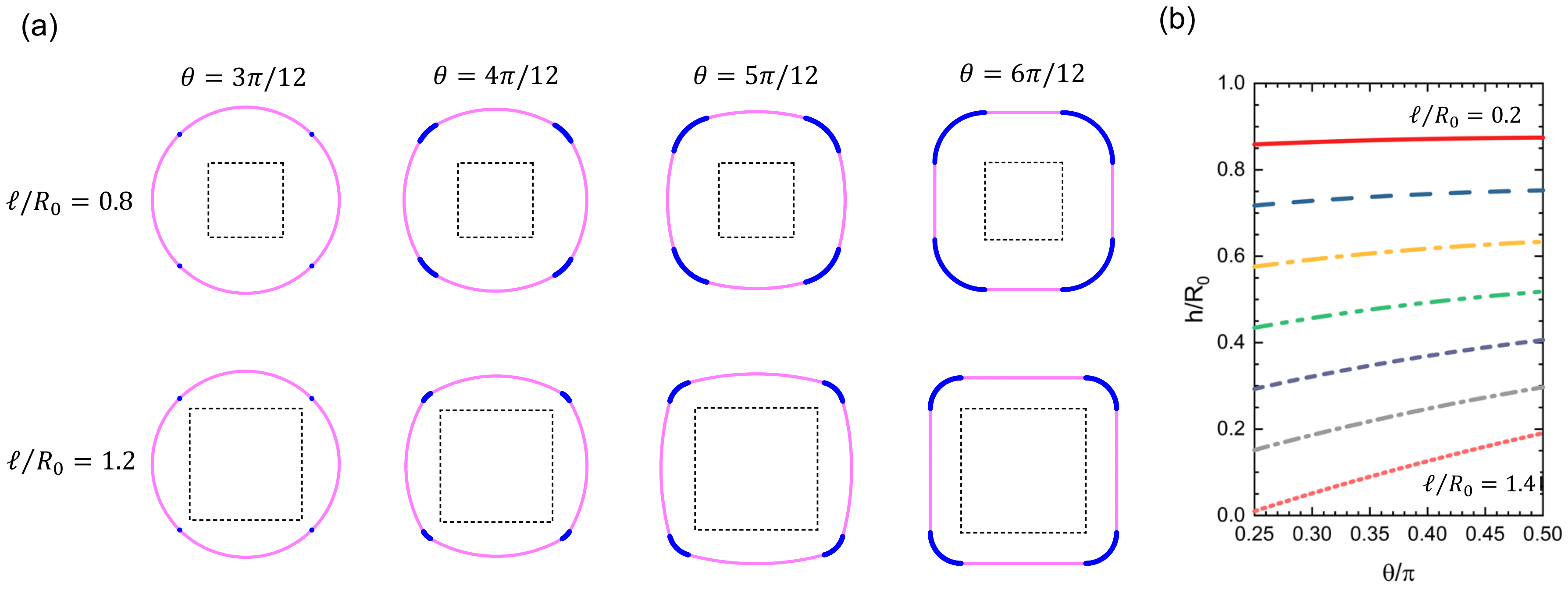
Figure 3a shows how the geometry varies with changing the values of
ℓ and
. In the drawing, we fixed the area to be constant as
, and the constant
was used as the unit of length in the model. Under such a constant-area condition,
h is not an independent variable, but a function of
ℓ and
, as follows from Equations (
1) and (
2).
Figure 3b shows the dependence of
h on
for various values of
ℓ, indicating that
h increases monotonically with
for every
ℓ. In particular, when
, the curve passes through the point
. For larger
ℓ, the
h-curve has an intersection with the
-axis at
. As a result, the definition range of
becomes limited to
with the lower limit
, which is an increasing function of
ℓ. Eventually, when
,
reaches
so that the curve shrinks to a point located at
, that represents a strict quadrangle with four right-angle corners.
Two square closed curves with rounded sides and filleted corners, drawn by the above-mentioned method, are arranged in a double concentric manner to create an approximate curve that resembles the cross-section of hollow square prisms found in square bamboos and other plants. An example is shown in
Figure 1b. The outer and inner closed curves that enclose the woody portion of the square bamboo are constructed by the parameter settings:
,
, and
for the outer curve and
,
, and
for the inner curve, respectively, with a common unit of length
. In the case of actual square bamboo, the shape of the cross-section changes depending on the height from the ground to the tip. We confirmed that many of them can be reproduced by setting appropriate parameter values
.
3. Cross-Sectional Performance
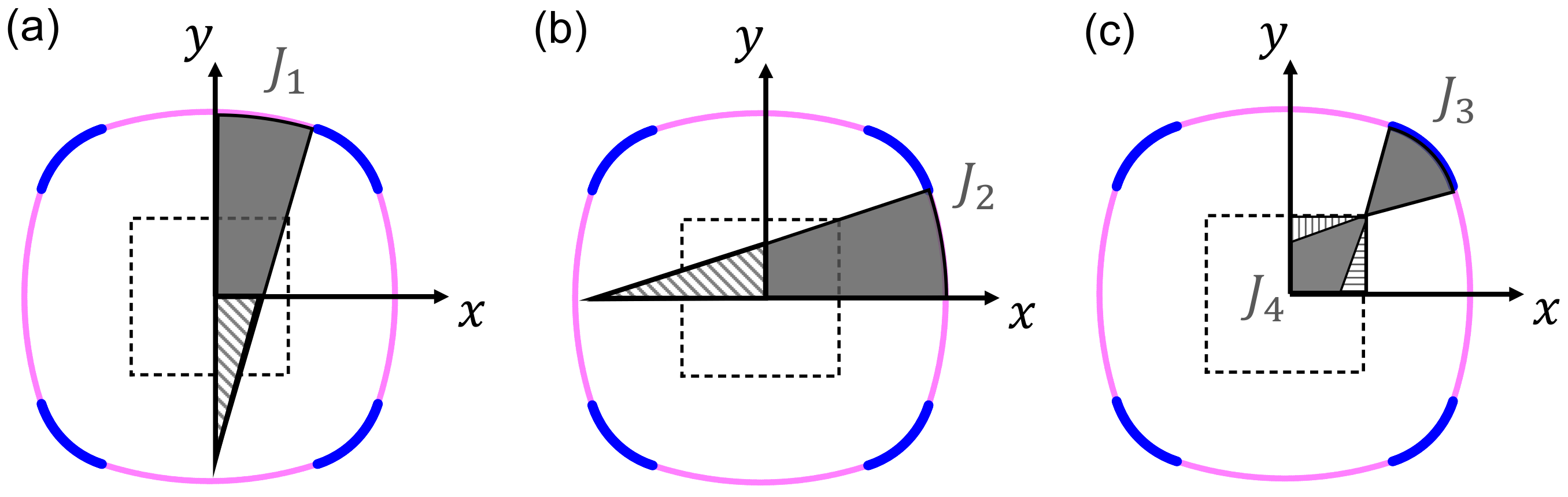
Our current aim is to evaluate the performance of rounded square cross-sections observed in square bamboo culm and other plant stems. Generally, for a given column, the cross-section performance measures the degree of contribution from the cross-sectional shape to the mechanical stability and strength of the column against external forces. It is characterized by four morphological quantities evaluated from the cross-sectional shape: the area A, the second moment of the area I, the gyration radius of the area , and the section modulus . Here, e is the greatest distance from an axis assigned to the cross-section to the extreme edge of the outer enclosing curve.
The following discussion will focus on how the latter two quantities,
and
Z, depend on the geometry of the cross-section, because the two are directly relevant to the mechanical stability and strength of the column, respectively. In plain words,
measures the buckling resistance of a column under axial compression, and
Z measures the yielding strength of it; these points will be revisited later. The actual calculation method of
and
Z will be explained in
Appendix A and
Appendix B. It should be noted that, in general, the values of
and
Z are dependent on the definition of the axis assigned to the cross-section. In the present study, we pay attention to the two different axis configurations as indicated in
Figure 1b, with respect to which the cross-sectional performance is examined. We shall find that
I (and
) takes the identical value for the two axes, even when the axis is rotated by an arbitrary angle in the same plane, because of the four-fold symmetry of the cross-section to be considered; see
Appendix C for details.
The effect of geometric variation on
can be addressed by introducing the improvement ratio,
, defined by:
Here,
is the gyration radius of the woody portion sandwiched by two concentrically arranged rounded squares; see
Figure 1b.
is the gyration radius of an annulus, obtained by
, having the same area as that of the rounded square-shaped woody portion. The improvement ratio
measures how
increases compared with the case of a simple annulus. When
takes a large absolute value with a positive (or negative) sign, it means that the gyration radius has increased (decreased) due to the change in cross-section shape from the simple annulus to a rounded square.
Similarly, we also define the improvement ratio of the section modulus of the system,
, defined by:
Similar to the case of gyration radius,
is the section modulus of the woody portion, and
is that of an annulus having the same area as the woody portion. Considering the dependence of
on the direction of the axis, as well as taking into account the four-fold symmetry of the cross-sectional shape, we chose the specific two axis configurations, labeled as Axis-1 and Axis-2, which are illustrated in
Figure 1b.
4. Numerical Conditions
Each of the two concentric rounded squares has a set of four geometric parameters: for the outer square and for the inner square. For both squares, the areas and are set to be unchanged in order for the area between the two concentric squares, , to remain constant, as well. These constant-area conditions make each of and dependent on the remaining three parameters, respectively.
In the following discussion, the relative ratio of to is set to , as a case study, without loss of generality of our conclusion, while will be used as the unit of length.
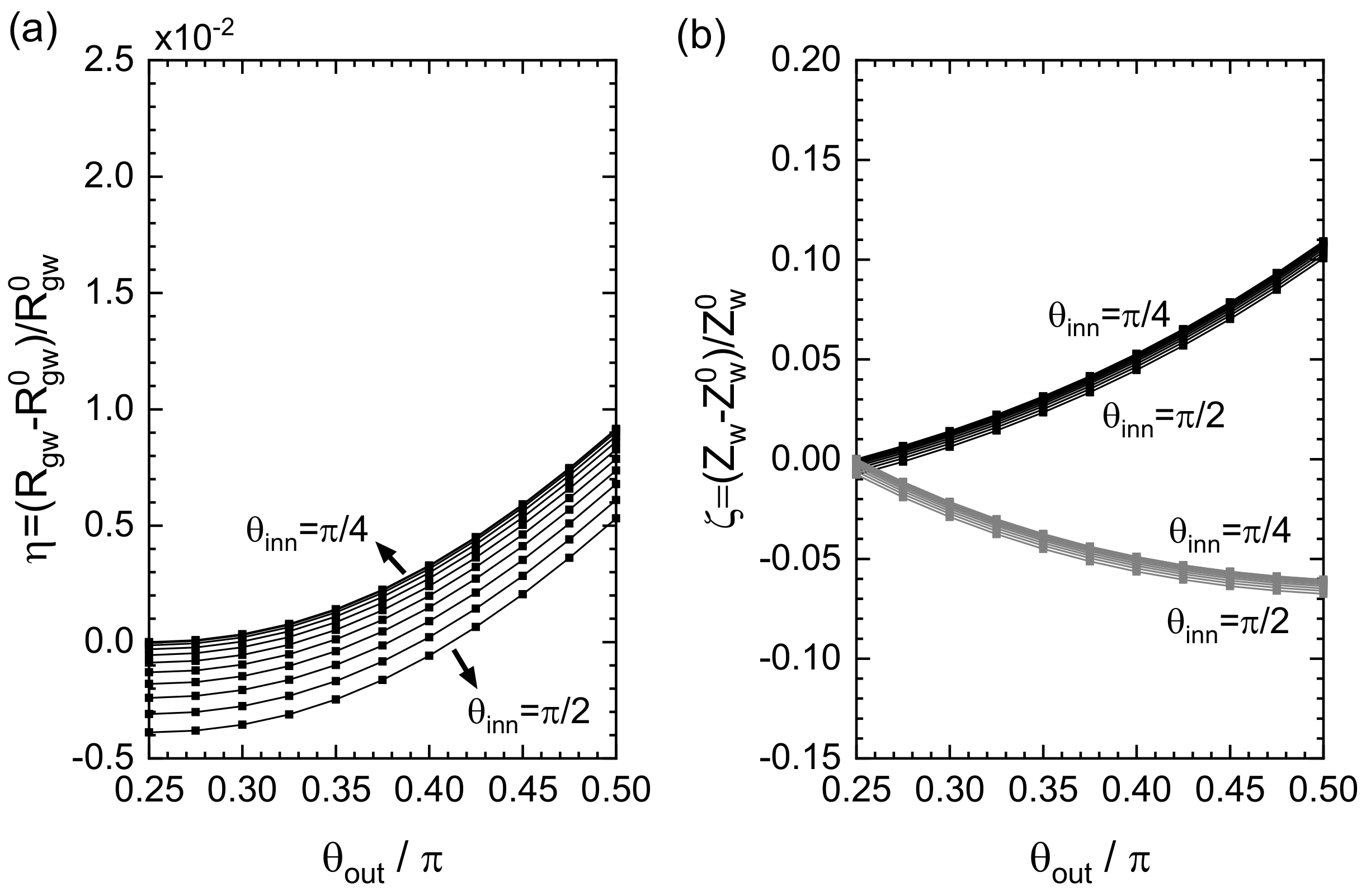
5. Results: Improvement Ratio
To examine the cross-sectional performance of the system, we changed the values of , , , and in a systematic manner to obtain the geometric dependences of and , only a part of which will be shown below.
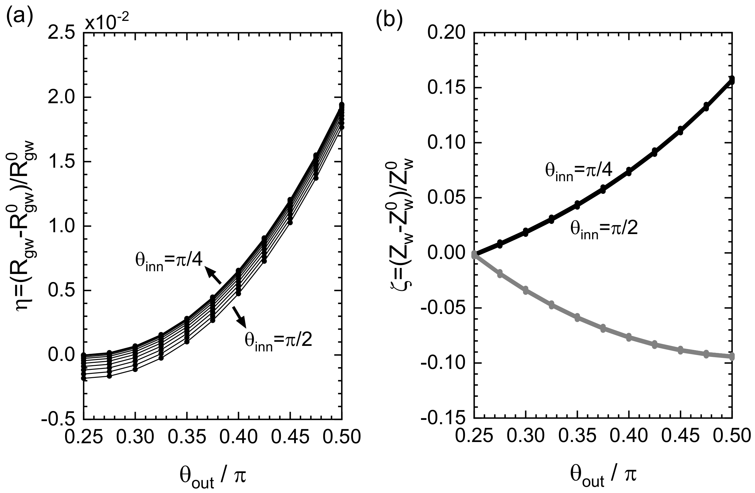
Figure 4a shows the improvement ratio
as a function of
and
. Other geometric parameters were set to be
and
in units of
. It was observed that
grew with
in a nearly parabolic manner without a local maximum peak for every choice of
, and the effect of
variation was insignificant under the present condition. The maximum value of
could be obtained at
and
, which corresponded to the hollow cross-section composed of a quadrangular-shaped outer curve and a circular-shaped inner curve. We saw that the maximum increment in
was a few percent at most, which will be intuitively understood by an analytic estimation discussed later.
Figure 4b shows the improvement ratio
for the section modulus. The upper branches (almost all of the curves with different
appear to be superimposed) correspond to the results with respect to Axis-1, and the lower branches to Axis-2. In the upper branches, a similar trend as that of
was observed, while the insensitivity to the change in
was more prominent. The increment obtained at the maximum was estimated to be 16 percent, which would give a feasible contribution to the mechanics of the hollow columns. This increment was attributed to the elongation of the distance
e from the axis to the extreme edge of the outer boundary, which was a direct consequence of the geometric variation in the cross-section from the simple circle to a rounded square.
If the magnitude relation between
and
was altered, the maximum increments in
and
were both depressed. An example is shown in
Figure 5, in which
and
were set in units of
. It thus turned out that, to obtain a greater
and
, it was advantageous to make the outer curve more square while making the inner curve more circular.
6. Discussion
6.1. Variable Range Estimation of and
Given the ratio of
, the maximum and minimum values of
could be roughly estimated by considering the following two extreme situations: (i) the outer curve is an exact quadrangular square with the enclosed area of
, and the inner curve is a simple circle with the enclosed area of
; and (ii) vice versa (i.e., the outer circular curve and the inner quadrangular curve with the definitions of the areas same as (i)). Suppose that
with a proportional constant
p. We then have:
and
Substituting
in accord with our numerical condition in Sec.IV, we obtain
for Case (i) and
for Case (ii). Therefore,
should take an intermediate value between the two extrema, as was consistent with our numerical results shown in
Figure 4a and
Figure 5a. A similar argument holds true for the maximum and minimum values of
.
6.2. Effect of the Fillet at the Vertices
It was proven that the cross-sectional performance was highest when the outer boundary was a quadrangle with sharpened vertices and the inner boundary was a circle [
27]. In practice, however, a strict quadrangle is not preferred as the outer boundary. This is because when the hollow prism is subjected to bending deformation, stress concentrations occur around acute vertices so that it locally breaks. To prevent the local breaking, it is better to fillet corners as suggested in the present model. We demonstrated that such filleted corners did not significantly reduce the cross-sectional performance of the hollow square prism, thus achieving the trade-off between the ideal performance obtained by sharpening the corners at the outer boundary and the suppression of the fragility at the corners realized by rounding them. This may be the wisdom of wild plants, while a certain physiological reason should also be possible for the preference of filleted corners.
It also should be noted that, even if the corners were filleted to some extent, the bending stress may be concentrated at the corner, causing premature failure. In order to clarify the stress distribution near the corners quantitatively, it is necessary to analyze the effect of stress triaxiality or perform finite element modeling, which is an interesting problem left for the future.
6.3. Implication for the Mechanical Rigidity and Strength
The relationship between cross-sectional shape and column mechanical stability and strength may need to be explained in more detail for readers outside the field. In structural mechanics, the gyration radius of the area,
, is known as a key quantity for comparing the buckling resistance of elastic columns with different cross-sectional shapes. Long columns often buckle when they receive an axial stress that exceeds a certain threshold value. The maximum compressive stress the column can withstand is called the buckling stress. An important fact is that the magnitude of the buckling stress is determined by
; more concretely, the larger
, the greater the buckling stress. The Euler column formula can be used to analyze the buckling of a long column with a load applied along the central axis:
In Equation (
7),
is the critical stress for the column to buckle,
E is the Young modulus of the material,
L is the column length, and the constant
c accounts for the end conditions of the column. The formula indicates that, in order to obtain a column structure that can withstand a large compressive stress, it is necessary to increase
. Our results proved that imparting convex rounded sides and filleted corners to the cross-section did not significantly degrade the large buckling resistance shown by strict rectangular square columns endowed with the maximum value of
.
The section modulus, Z, is another key quantity for considering the mechanical stability of elastic columns. Z measures the strength of a column; the higher the section modulus, the higher will be the resistance to yield under bending. By multiplying Z with the yield strength of the constituent material of the column, we can calculate the upper limit bending moment, , that the column can withstand without plastic deformation. Our results showed that the rounded square cross-section was beneficial for securing a large value of compared with the case of a circular cross-section, which may be one of the reasons why a kind of plant stem exhibits the rounded square cross-sections.
It is also noteworthy that the second moment of area, I, is also important for evaluating the cross-sectional performance. It represents the degree of bending stiffness of a column. Multiplying I by E of the constituent material, we obtained the bending stiffness of the column. Since in the present work, the area of cross-section A was fixed, the relation of holds for every system under consideration; in this case, the effect of I on the cross-sectional performance can be deduced easily from that result of .
6.4. Versatility of the Theoretical Model
As a closing remark, we mention the scope of application of our mathematical model to actual wild plants. When you observe culms and stems of actual plants, you will find that the shape of the cross-section is not uniform, but gradually changes along the height direction. Therefore, the morphological quantities that characterize the cross-sectional performance of the plants, such as , and Z, generally change depending on the height from the ground. Our model was effective at dealing with such problems. In fact, the theoretical model developed in this study could change the cross-sectional shape continuously by properly controlling the parameter values. Therefore, by collecting the actual measurement data of the cross-section of the plant and reproducing the shape of each cross-section with different heights by the model, it was possible to estimate the change in cross-sectional performance along the height direction accurately. This made it possible to analyze the three-dimensional mechanical behavior of hollow columnar plants with a polygonal cross-section, such as square bamboo.
It also should be emphasized that the model we developed could be extended to triangles, pentagons, hexagons, and other arbitrary polygons in a straightforward manner. This is realized by replacing the reference square depicted in
Figure 2 with another kind of polygon, followed by the same drawing procedure of long and short arcs.
Figure 6a shows an example of a rounded triangle, whose shape looks similar to the cross-section of a papyrus (
Cyperus microiria) given in
Figure 1d. Furthermore, it is possible to break the discrete rotational symmetry of the model, by setting a different value of
at each vertex.
Figure 6b shows such an example of a rounded square with no rotational symmetry. By extending this model in the above-mentioned way, it becomes possible to reproduce more faithfully the cross-section of polygonal stems, culms, and branches of actual plants whose shape should vary considerably from sample to sample in general. In future work, we plan to measure the cross-sectional shape of square bamboo in detail and reproduce it numerically using the present model.


