Article

Graphical Modeling and Simulation for a Multi-Aircraft Collision Avoidance Algorithm based on Collaborative Decisions

College of systems engineering, National University of Defense Technology, Changsha 410073, China
*
Author to whom correspondence should be addressed.
Symmetry 2020, 12(6), 985; https://doi.org/10.3390/sym12060985
Submission received: 17 April 2020 / Revised: 25 May 2020 / Accepted: 5 June 2020 / Published: 9 June 2020

Abstract

:
The Traffic Alert and Collision Avoidance System (TCAS) is recognized worldwide as the last resort for avoiding midair collisions. The existing TCAS can solve pairwise conflict effectively, but cannot manage multi-aircraft conflict satisfactorily, and more seriously, can even trigger domino conflicts in some situation. In response to the increasingly frequent multi-aircraft conflicts, especially three-aircraft conflicts, it is necessary to improve the ability of TCAS. This paper studies the collision avoidance of multi-aircraft scenarios and innovatively proposes a collaborative optimization of a collision avoidance system (CAS) based on the state prediction of the aircraft. In the process, not only invading aircraft but also potential invading aircraft are considered in the plan for an optimal conflict resolution program. From the perspective of mathematics, the collaborative multi-aircraft conflict detection and resolution algorithm is described in detail in this paper. In the end, this paper conducts a comparative experiment to prove the feasibility of the algorithm in three-aircraft scenarios using InCAS software and Gmas simulation software based on graphical modeling of complex systems. The experimental results show that the CAS proposed in this paper can efficiently prevent the occurrence of domino conflicts and guide each aircraft to avoid conflict areas and return to their origin trajectories. In contrast, the existing TCAS will cause the target aircraft to intensify the conflict with the potential invading aircraft when avoiding intruder aircraft. The research greatly remedies the gaps in the area of multi-aircraft collision avoidance and greatly improves the ability and efficiency of TCAS.

1. Introduction

The Traffic Alert and Collision Avoidance System (TCAS) is widely installed in civil aircraft and other large aircraft. TCAS is recognized worldwide as last-resort means of avoiding midair collision [1]. By asking and receiving responses, TCAS gets the location and speed information from nearby aircraft to determine whether they pose a threat to the target aircraft. If so, TCAS issues resolution advisories (RAs) and guides aircraft to avoid a collision.
With the soaring demand for aviation, the volume of air traffic has risen sharply, the airfield and other surrounding airspace are also increasingly crowded, and the possibility of multi-aircraft conflict is increasing. Under normal circumstances, the aircraft along the aerial path will not threaten each other. However, due to the fault of ground tower command, improper operation of the pilot, bad weather, and so on, multi-aircraft conflicts have become more frequent in recent years. In multi-aircraft conflict, more than 95% are three-aircraft conflicts [2].
For example, in 2012, at the Reagan airport in Washington, USA, loopholes of ground tower command almost led to the collision of three fully-loaded aircraft. TCAS can solve pairwise conflict well, but it cannot manage multi-aircraft conflicts satisfactorily, and can even induce a domino conflict. According to research, the failure rate of TCAS in dealing with multi-aircraft conflicts is two times as high as that of pairwise conflicts, and the probability of intensifying a conflict or inducing accidental conflict is 5 times higher [1].
TCAS has been developed continuously since 1950 [3,4]. J. L. Garcia et al. [5] conducted a human factor analysis of operational errors in TCAS. M. J. Kochenderfer et al. [6] used dynamic programming to improve the robustness of TCAS and effectively reduced the probability of false alarms. B. K. Jun [7] greatly improved the effectiveness of TCAS by replacing the traditional tracker with a Kell Mann filter. L. Peng et al. [8] studied a new generation of collision avoidance systems based on GPS and Automatic Dependent Surveillance Broadcast (ADS-B), and proposed two horizontal strategies of collision avoidance. One is to change the horizontal flight direction only; the other is to change the horizontal velocity only. F. Romli et al. [9] evaluated the impact of ADS-B on the performance of collision avoidance and verified by simulation experiments that ADS-B could improve TCAS performance slightly. D. L. Woodell et al. [10] improved TCAS by introducing higher resolution radar, which not only provided height information for aircraft without an automatic height reporting system but also provided angle perspective for air traffic, thus enhancing situation awareness of TCAS. TCAS instructions sometimes trigger new conflicts. For example, TCAS may issue resolution advisories (RAs) based on the current conflict without considering the consequences of the next stage, which may lead to potential conflicts. J. Tang et al. [11] formalized a conflict model to identify those potential conflicts. In other research, J. Tang conducted a systematic overview of previous studies on TCAS, including the various analytical research and the different improvement strategies. Then, he offered a direct view and indepth comprehension of the potential conflict occurrence for risk assessment [12]. By assuming the precise state information of aircraft, C. Munoz et al. [13] presented a mathematical model for the RA logic of TCAS II and further presented an algorithm for RA detection. As an emerging technology with significant market potential, unmanned aerial vehicles (UAVs) play a vital role in many applications [14]. I. Mahjri [15], J. Meyer [16], and P. Liangfu et al. [17] have discussed the application of TCAS to collision avoidance of UAVs, demonstrated its feasibility, and given specific strategies. Yang et al. [18] studied the UAV conflict problem and presented a taxonomy of conflict situations. Furthermore, they proposed a two-layered optimization algorithm to solve the conflict detection and resolution (CDR) problem. In other research by Yang et al. [19], a tree search algorithm is applied to find out the near-optimal collision avoidance solution for UAVs. Pérez-Castán et al. [20] aim to solve the safety problem that is caused by the integration of UAVs and traditional aircraft in overlapping airspace. Based on the assessment of conflict-risk, they proposed a framework to design and program the airspace [21].
In Table 1, we can see researchers have studied the shortcomings of TCAS in various aspects such as logical algorithms, equipment, and human factors, and proposed a series of solutions. Many of these research results have been adopted by a new generation of TCAS.
The summary also shows that the study of TCAS is mainly focused on improving its ability to handle pairwise conflict. Only a few studies concentrate on multi-aircraft conflicts, such as T. B. Billingsley [22], who discussed the effect of TCAS solving multi-aircraft conflicts, and J. Tang [11], who pointed out that there is a "four aircraft deadlock" vulnerability in TCAS. Still, few studies have deeply discussed the solution of multi-aircraft conflicts. Therefore, in view of the increasing frequency of multi-aircraft conflicts, especially three-aircraft conflicts, TCAS needs to be improved to make up for the lack of ability to deal with multi-aircraft conflicts. In this way, it can effectively cope with the increasingly frequent flight conflicts and build up the last line of defense for aviation security.

2. Improved TCAS Model

A conflict is a situation where two aircraft have lost standard separation, and if their tracks are extrapolated into the future without pilot intervention, there is a great possibility of collision or near-midair collision (NMAC). Three-aircraft conflicts exist in two scenarios. One situation is that any two of the three aircraft conflict with each other, and the time interval between involved aircraft arriving at the closed point of approach (CPA) is less than 10 seconds. The other situation is induced by improper TCAS instructions. When the two aircraft in a pairwise conflict make collision avoidance maneuvers in accordance with TCAS instructions, the involved aircraft then conflict with the third aircraft. The latter situation is discussed in this paper. As is depicted in Figure 1, Aircraft 1, 2, and 3 appear in a narrow airspace, and there exists a three-aircraft conflict. In our conflict scenario, three aircraft are, respectively, defined as the target aircraft, the intruder aircraft, and the potential intruder aircraft. The target aircraft is the one equipped with TCAS, the intruder aircraft is the first invader aircraft into conflict with the target aircraft, and the potential intruder aircraft is the secondary invader aircraft into the conflict. All aircraft are equipped with Mode S transponders.
When facing multi-aircraft conflict, the TCAS solution is to convert multi-aircraft conflict into multiple pairwise conflicts and issue a series of Ras, one by one in sequence. As is depicted in Figure 1, Aircraft 1 and 2 step into conflict first, and TCAS issues RAs for the first time according to the condition. Hereafter, Aircraft 2 and 3 step into conflict, and TCAS issues RAs for the second time. Soon after, Aircraft 1 and 3 step into conflict, and TCAS issues RAs once again. If the interval time between RAs is adequate for aircraft to complete the instructions of collision avoidance, then TCAS can handle three-aircraft conflict well. However, in some particular situations, which we will demonstrate later, TCAS cannot solve the conflict well.
For some particular three-aircraft conflicts, there exist several defects in TCAS. First, there exists the Tang-Piera four aircraft deadlock. This also applies to three-aircraft conflict. As is depicted in Figure 2a, TCAS suggests that Aircraft 1 climb and Aircraft 3 descend to avoid a collision. The instruction induces another collision between Aircraft 1 and 2. Due to close distance, the pilot may lack time to response and fail to avoid a collision. Second, TCAS does not consider two invader aircraft simultaneously. When facing two invader aircraft from opposite directions at the same time, TCAS may issue contradictory instructions like “climb” and “level off” within a short time. As is depicted in Figure 2b, TCAS suggests that Aircraft 1 climb and Aircraft 2 descend to avoid collision, and the climbing Aircraft 1 then steps into conflict with Aircraft 3. Although still in collision with Aircraft 2, Aircraft 1 receives instructions to descend to avoid collision with Aircraft 3. This certainly intensifies the collision between Aircraft 1 and Aircraft 2. During the procedure, due to the contradictory instructions, all three aircraft are always in conflict. Last, in the face of multi-aircraft domino conflicts, the target aircraft must undergo multiple rapid ascents and descents to avoid a collision. This often exceeds the aircraft’s pitch angle and acceleration limits.
Considering that the existing TCAS mainly deals with pairwise conflict, cannot solve three-aircraft conflict satisfactorily, and can even induce a new collision, this paper improves TCAS greatly by proposing a collaborative CAS for multi-aircraft scenarios based on graphical modeling of complex systems. In this algorithm, the existing TCAS is improved to make sure that the target aircraft chooses the correct direction and intensity to avoid all intruder and potential intruder aircraft. Figure 3 shows the proposed CAS strategy under the collaboration mechanism. For the current multi-aircraft flight situation in local airspace, there is an effective CAS communication connection between adjacent aircraft, and all related aircraft form a collaborative system. The current flight status shared within the system is used as input to the collaborative decision-making module. The output to the collaborative decision-making module is safe flight situations, that is, all possible future situations, especially the risk of chain collisions, and optimal resolutions. Aircraft cooperation in the airspace chooses a flight strategy that does not cause cascading conflicts and strictly avoids the situation of cascading collision risks. Therefore, the CAS action time is widened, and the CAS action performance is improved.
As shown in the collaborative decision-making module in Figure 3, the target aircraft monitors the surrounding airspace, predicting the trajectory of other aircraft based on the input that includes their position, speed, and other information. According to their trajectory, the proposed CAS on the target aircraft determines whether the aircraft nearby pose threats to the target aircraft. In the module of situation judgment, the existing TCAS just determines if there is an invader aircraft. In contrast, for the proposed CAS, when it judges if there is an intruder aircraft, it still monitors other aircraft around, judging whether there is a potential intruder aircraft. According to the situation, the proposed CAS determines whether or not there is a pairwise or multi-aircraft conflict. Then it makes strategic choices of conflict resolution about the direction and intensity. Additionally, the collaborative mechanism will optimize the resolution advisories according to the shared information and the coordinated principles.

3. Conflict Detection Algorithm

3.1. Trajectory Prediction Algorithm

This paper focuses on the anticollision research of operational aircraft, which has a small-time span and a compact distribution. Therefore, this paper adopts the Euclidean three-dimensional space (no curvature) model, which greatly reduces the computational work [11]. The airspace where the three-aircraft scenario is located is cleverly divided into the same gridding, marked with 3D coordinates. Then the 4D location information database of all the aircraft in the airspace can be constructed by adding the time information.
At moment t, there are two aircraft named i and j in a certain airspace. The 3D position of aircraft i and j are p t i = ( x x , t i , x y , t i , x z , t i ) T and p t j = ( x x , t j , x y , t j , x z , t j ) T , respectively. The 3D velocity of aircraft i and j are v t i = ( v x , t i , v y , t i , v z , t i ) T and v t j = ( v x , t j , v y , t j , v z , t j ) T , respectively. As is depicted in Figure 4a, the horizontal position of aircraft i and j are p h t i = ( p x , t i , p y , t i ) T and p h t j = ( p x , t j , p y , t j ) T , respectively. The horizontal velocity of aircraft i and j are v h t i = ( v x , t i , v y , t i ) T and v h t j = ( v x , t j , v y , t j ) T , respectively.
As is depicted in Figure 4b, the horizontal distance of aircraft i relative to j is d h t i j = p h t i p h t j . In addition, the relative horizontal speed is v h t i j = v h t i v h t j , whose component in the x-axis direction is v x , t i j and the component in the y-axis direction is v y , t i j . Accordingly, the component of the horizontal relative distance in the x-axis direction is d x , t i j and the component in the y-axis direction is d y , t i j .
During the procedure, there exists a moment when the separation of aircraft i and j is the smallest. This position is defined as the closest point of approach (CPA), including CPAh, (CPA in the horizontal direction), where horizontal distance is smallest, and CPAz (CPA in the vertical direction) where vertical distance is smallest.
As is depicted in Figure 4b, when the two aircraft reach CPAh., the following prerequisite needs to be satisfied:
d h i j = m i n   d h t i j | t ( 0 , T ) .
At moment t, τ h , t i j is defined as the time spent for aircraft i and j to reach CPAh (CPA in the horizontal direction), supposing they keep current flight status unchanged, i.e.,:
τ h , t i j = | d ^ h , t i j | · cos ( δ t i j φ t i j ) | v ^ h , t i j | .
δ t i j = tan 1 ( v x , t i j v y , t i j ) .
φ t i j = tan 1 ( d x , t i j d y , t i j ) .
Define m i n   d h t i j as the smallest distance between aircraft i and j, the distance is as follows when they reach CPAh, i.e.,:
d h i j = d h , t   +   τ h , t i j i j = p h , t   +   τ h , t i j i p h , t   +   τ h , t i j j .
At moment t, τ z , t i j is defined as the time spent for aircraft i and j to reach CPAz, i.e.,:
τ z , t i j = | d z , t i j v z , t i j | .
d z , t i j = x z , t i x z , t j .
v z , t i j = v z , t i v z , t j .
Define d z , t   +   τ h , t i j i j as the vertical distance when aircraft i and j reach CPAh:
d z , t   +   τ h , t i j i j = x z , t   +   τ h , t i j i x z , t   +   τ h , t i j j .
x z , t   +   τ h , t i j i = x z , t i v z , t i · τ h , t i j .
x z , t   +   τ h , t i j j = x z , t j v z , t j · τ h , t i j .

3.2. Pairwise Conflict Detection Algorithm

A pairwise conflict detection algorithm is used to judge whether there is a conflict between the two aircraft. As long as either of the following two conditions is met, a pairwise conflict is determined.
1.
Time spent for aircraft i and j to reach CPAh and CPAz ( τ h , t i j and τ z , t i j ) are both less than the time threshold TimeRA, and horizontal distance when they reach CPAh | d h , t   +   τ h , t i j i j | is smaller than distance modification (DMOD), and vertical distance when they reach CPAZ | d z , t   +   τ h , t i j i j | is smaller than the vertical threshold value (ZTHR). The time and space thresholds used to define whether a collision will occur vary with different sensitivity levels (SLs) based on altitude [23].
( 0 < τ h , t i j < T i m e R A 0 < τ z , t i j < T i m e R A ) ( | d h , t   +   τ h , t i j i j | < D M O D | d z , t   +   τ h , t i j i j | < Z T H R ) .
2.
Horizontal and vertical distance between aircraft i and j ( d h , t i j and d z , t i j ) are less than the threshold separately.
( | d h , t i j | < D M O D ) ( | d z , t i j | < Z T H R ) .

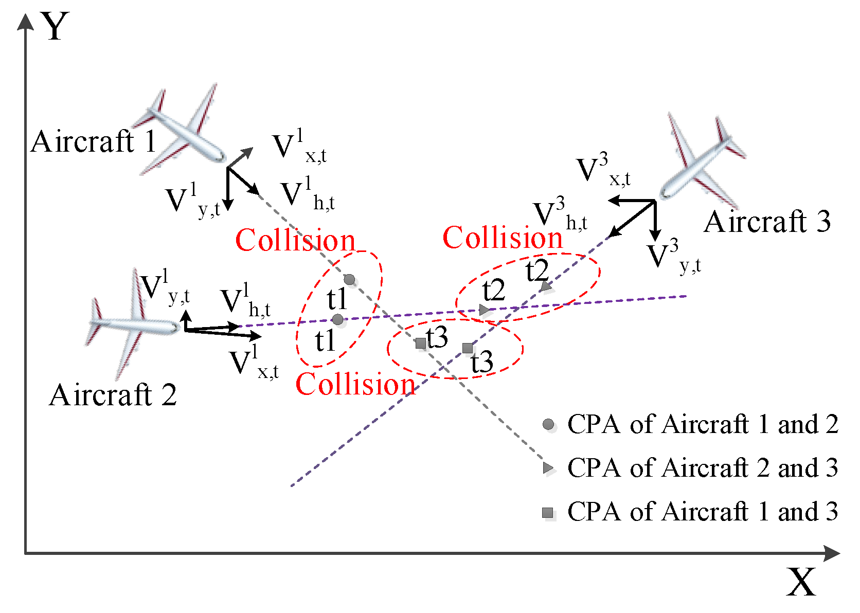
3.3. Multi-Aircraft Conflict Detection Algorithm

Since more than 95% of current multi-aircraft conflicts are three-aircraft conflicts, we will use the three-aircraft scenario as an example to introduce the algorithm logic of multi-aircraft conflict detection. Supposing there are three aircraft, i, j, and m, in a narrow airspace, they are defined as the target aircraft, the invader aircraft, and the potential invader aircraft. The proposed CAS firstly determines whether there is a pairwise conflict. If so, the proposed CAS continues to judge if the third aircraft would pose a threat to either of the first two aircraft, supposing that the third aircraft keeps its flight status unchanged and the first two aircraft obey the instruction of TCAS. If so, there is a three-aircraft conflict. In other words, the following conditions should be satisfied when three aircraft come into conflict.
(1)
At moment t, there are two aircraft among aircraft i, j, m coming into conflict firstly.
[   ( 0 < τ h , t i m < T i m e R A 0 < τ z , t i m < T i m e R A ) ( | d h , t i m | < D M O D | d z , t i m | < Z T H R )   ] [   ( 0 < τ h , t i j < T i m e R A   0 < τ z , t i j < T i m e R A ) ( | d h , t i j | < D M O D | d z , t i j | < Z T H R )   ] [   ( 0 < τ h , t j m < T i m e R A 0 < τ z , t j m < T i m e R A ) ( | d h , t j m | < D M O D | d z , t j m | < Z T H R )   ]  
(2)
Before moment t + Δ t , the third aircraft will come into conflict with either of the first two aircraft (supposing aircraft i and aircraft j come into conflict at moment t first, then aircraft m and aircraft i come into conflict).
( 0 < τ h , t   +   Δ t i m < T i m e R A 0 < τ z , t   +   Δ t i m < T i m e R A ) ( | d h , t   +   Δ t i m | < D M O D | d z , t   +   Δ t i m | < Z T H R ) .
t + Δ t is the moment when the conflict between the pair of aircraft is cleared under the instruction of the existing TCAS, supposing there is no third invader aircraft.

4. Collaborative Conflict Resolution Algorithm

Each aircraft in the collaborative system shares the situation information of neighboring individuals. The collaborative mechanism guarantees the information sharing and principle consistency between aircraft in conflict scenarios. When the conflict detection module detects threats, the target aircraft generates candidate conflict resolution strategies based on the threat aircraft’s situation. The trajectory prediction module will predict the trajectories of the candidate strategies and share them with other aircraft in the system. The collaborative decision-making module determines the optimal strategy combination based on the shared predicted trajectories. Each aircraft performs maneuvering in accordance with the optimal strategy combination to avoid collision. The algorithm flow is shown in Figure 5.
In the next part of this section, we first introduce the pairwise conflict resolution algorithm, which is the basis of the collaborative conflict resolution algorithm, and this will help us better understand the algorithmic logic of multi-aircraft conflict resolution. Then, we illustrate the multi-aircraft conflict resolution algorithm with the three-aircraft scenario. It is not only because, currently, more than 95 percent of multi-aircraft conflicts are three-aircraft conflicts, but also the problem of three-aircraft conflict resolution needs to be solved urgently. Hence our algorithm should be able to be verified in the three-aircraft conflict first.

4.1. Pairwise Conflict Resolution Algorithm

The pairwise conflict resolution algorithm is not only an effective solution for two-aircraft conflict but is also the basis of the candidate-strategies-generating module in a multi-aircraft conflict resolution algorithm. In the following, we take the paired conflict between aircraft i and aircraft j as an example to describe the pairwise conflict resolution algorithm.

4.1.1. Direction Choosing

At moment t, an RA for the target airplane is issued. The CAS will determine a choice of direction, which provides maximum vertical separation at CPAh under the assumption that the intruder aircraft maintains its air route. As is depicted in Figure 6, define a as vertical separation at CPAh when the target aircraft choose to maneuver upward; define b as vertical separation at CPAh when the target aircraft choose to maneuver downward. Altitude limitation (ALIM) is the threshold set to ensure that the aircraft does not collide at the closest approach point, which usually varies with the flight altitude.
a = | p z , t   +   τ h , t i j i ( u p ) p z , t   +   τ h , t i j i ( n o r m a l ) | .
b = | p z , t   +   τ h , t i j i ( d o w n ) p z , t   +   τ h , t i j i ( n o r m a l ) | .
p z , t   +   τ h , t i j i ( d o w n ) = p z , t i + ( v z , t i Δ z , t i ) · τ h , t i j .
p z , t   +   τ h , t i j i ( n o r m a l ) = p z , t i + v z , t i · τ h , t i j .
p z , t +   τ h , t i j i ( u p ) = p z , t i + ( v z , t i + Δ z , t i ) · τ h , t i j .
where Δ z , t i has a fixed value of 1500 feet/min, temporarily representing the same intensity of speed change.
The collaborative conflict resolution algorithm follows the following principles when selecting the optimal maneuver direction:
(1)
Maximum vertical separation principle: The target aircraft needs to achieve maximum vertical separation from the intruder aircraft at CPAh in the case of the same intensity of speed change.
(2)
Noncrossing principle in the vertical direction: When maneuvering upwards or downwards, target aircraft should achieve the goal of not-crossing with the invader aircraft in the vertical direction as much as possible [24].
The model of direction choosing is as follows: the target aircraft chooses to maneuver upwards when c t i = 1 , the target aircraft chooses to maneuver downwards when c t i = 1 , the target aircraft maintains flight when c t i = 0 .
c t i = { 1 ,       ( b > a ) ( a < A L I M ) ( b a ) ( ε ( 0 , τ R A ]   s u c h   t h a t d z , t   +   ε i j = 0 ( b A L I M ) ) 1 ,       ( b a ) ( b < A L I M ) ( b > a ) ( ε ( 0 , τ R A ]   s u c h   t h a t d z , t   +   ε i j = 0 ( a A L I M ) ) 0 ,                                    o t h e r s                                      

4.1.2. Intensity Choosing

Once the direction is chosen, the collaborative mechanism will help the proposed CAS by determining the adequate intensity of speed change. The intensity needs to take speed, track, and other information of both aircraft into consideration to guarantee not only at least ALIM vertical separation, but also minimal speed change. v z , t i is the vertical speed of the target aircraft before TCAS issues an RA at moment t. Δ z , t i is the intensity of speed change. v z , t i * is the vertical speed of target aircraft after CAS issues an RA.
v z , t i * = v z , t i + Δ z , t i .
Δ z , t i = { [ A L I M + ( p z , t j + v z , t j · τ h , t i j ) ( p z , t i + v z , t i · τ h , t i j ) ] τ h , t i j ,         c t i = 1 [ A L I M + ( p z , t j + v z , t j · τ h , t i j ) ( p z , t i + v z , t i · τ h , t i j ) ] τ h , t i j ,            c t i = 1

4.1.3. Original Trajectory Recovery Algorithm

As is depicted in Figure 7, when target aircraft has passed CPAh, CAS judges whether the conflict has been cleared. If so, the target aircraft adjusts its vertical speed to restore its original flight state. Otherwise, the target aircraft keeps its speed unchanged.
c t + τ h , t i j i = { c t i ,        d z , t + τ h , t i j i j A L I M c t i ,             o t h e r w i s e    .
If the conflict has been cleared, target aircraft i restores its original flight state through Steps (1) and (2).
  • At moment t + τ h , t i j , target aircraft i is at CPAh. Through a change of vertical speed, target aircraft i has achieved adequate vertical separation from the invader aircraft at CPAh. After being cleared of conflict, the target aircraft adjusts vertical speed to return to its original altitude. v z , t   +   τ h , t i j i is the speed of the target aircraft before adjustment, v z , t   +   τ h , t i j i * is the vertical speed after adjustment, time of adjustment is τ h , t i j .
v z , t   +   τ h , t i j i * = v z , t   +   τ h , t i j i Δ z , t   +   τ h , t i j i = v z , t i * Δ z , t   +   τ h , t i j i .
Δ z , t   +   τ h , t i j i = 2 Δ z , t i .
  • At moment t + 2 τ h , t i j , target aircraft i will have returned to its original altitude, then it adjusts to its original speed.
v z , t   +   2     τ h , t i j i * = v z , t   +   2     τ h , t i j i + Δ z , t i = v z , t i .
After two steps, the target aircraft will have cleared the conflict and is restored to its original state.

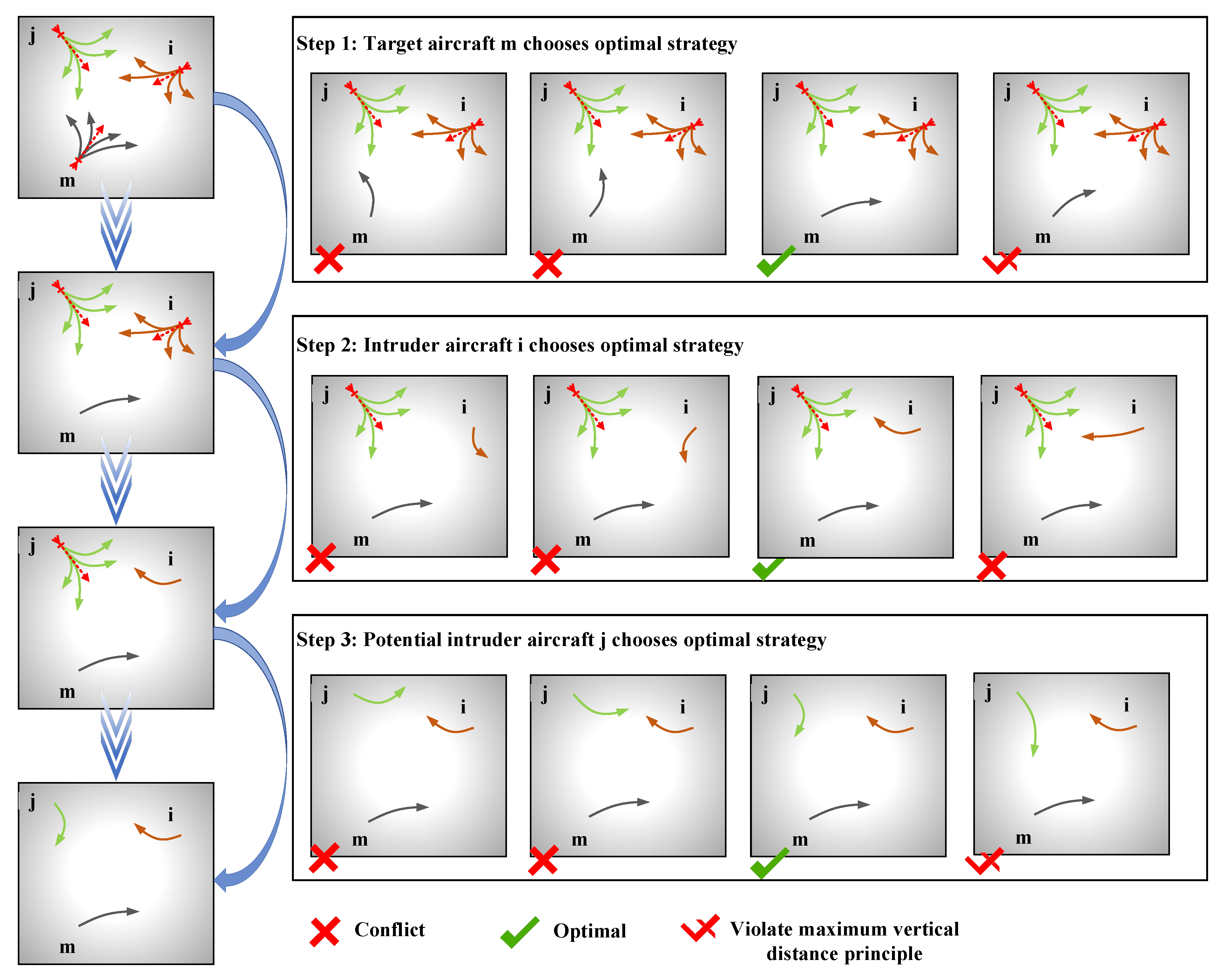
4.2. Multi-Aircraft Conflict Resolution Algorithm

4.2.1. Candidate-Strategies-Generating Module

The algorithm of the candidate-strategies-generating module is a variant of the pairwise conflict resolution algorithm. The candidate strategies for the target aircraft is the set of all resolution strategies that are considered when a pairwise conflict with a single aircraft occurs. Taking the three-aircraft conflict scenario as an example, the candidate strategies for aircraft m consists of two parts. One part is the resolution strategies generated by aircraft m facing a conflict with invading aircraft i. The other part is the resolution strategies generated by aircraft m facing a conflict with the potentially invading aircraft j. Similarly, the candidate strategies for aircraft i and aircraft j are also formed in this way. It can be seen from the pairwise conflict resolution algorithm that every aircraft has two strategies to choose from when the two aircraft are in conflict alone. For example, taking aircraft m as the target aircraft in the three-aircraft scenario, it is obvious that aircraft m has two choices of maneuver strategies, respectively, in the face of conflict with i and j. In other words, aircraft m has 4 alternative maneuver strategies. Therefore, in the three-aircraft conflict scenario, there are 64 combinations of maneuver strategies between the three aircraft. Figure 8 shows one combination of candidate strategies.
We assume that there will a three-aircraft conflict in a narrow airspace. Supposing at moment t, two of the three aircraft come into conflict first. Each of the two aircraft will reach their CPAh after the time of τ h , t m i , τ h , t m j , τ h , t i j , respectively. c t =   1 or −1 means the direction of collision avoidance is “climb” or “descend”. For example, c t m i = 1 means that aircraft m chooses the “climb” maneuver when facing the conflict with aircraft i; c t j m = 1 means that aircraft j chooses the “descend“ maneuver when facing the conflict with aircraft m.
It can be seen from the pairwise conflict resolution algorithm that when aircraft m faces a conflict with aircraft i alone, there are two resolution strategies. Δ z , t m i and Δ z , t m j are the speed change intensity when the aircraft m makes a collision avoidance maneuver.
Δ z , t m i = { [ A L I M + ( p z , t i + v z , t i · τ h , t m i ) ( p z , t m + v z , t m · τ h , t m i ) ] τ h , t m i ,           c t m i = 1 [ A L I M + ( p z , t i + v z , t i · τ h , t m i ) ( p z , t m + v z , t m · τ h , t m i ) ] τ h , t m i ,          c t m i = 1
When aircraft m faces a conflict with aircraft j alone, there are also two resolution strategies:
Δ z , t m i = { [ A L I M + ( p z , t j + v z , t j · τ h , t m j ) ( p z , t m + v z , t m · τ h , t m j ) ] τ h , t m j ,            c t m j = 1 [ A L I M + ( p z , t j + v z , t j · τ h , t m j ) ( p z , t m + v z , t m · τ h , t m j ) ] τ h , t m j ,          c t m j = 1
Similarly, the candidate strategies for aircraft i and j can be derived, so all candidate conflict resolution strategies are shown in summary in Table 2.

4.2.2. Collaborative Decision-Making Module

The collaborative decision-making module shown in Figure 9 is the core of the collaborative multi-aircraft conflict resolution algorithm. After the collaboration, the proposed CAS selects an optimal strategy combination from the 64 candidate strategy combinations that can ensure the resolution of all conflicts.
We assume that aircraft m receives the RA first, which means that aircraft m must make the strategic choice first. The basis for decision-making is the principle of threat aircraft trajectory information and the maximum vertical distance principle. Therefore, aircraft m should choose a strategy that does not collide with other threatening aircraft (potential intruder j), while avoiding collision with the most threatening aircraft (intruder i). When there are multiple selectable strategies, the choice is made according to the principle of maximum vertical distance to increase the fault tolerance of the algorithm. After target aircraft m determines the optimal strategy, it shares its decision. Then, the intruder i determines its optimal collision avoidance strategy according to the decision of aircraft m and shares it. Finally, the potential intruder j selects the optimal strategy based on the optimal collision avoidance strategy of aircraft m and i to eliminate the potential threats. At this point, all aircraft have completed the selection of collision avoidance maneuvers with the help of a collaborative decision-making module, forming an optimal strategy combination to achieve conflict resolution.

5. Simulation

In this chapter, we simulate a three-aircraft scenario and conduct a contrast simulation to verify the algorithm’s effectiveness. By recording waypoints of trajectories and analyzing the aircraft’s status in the procedure, we can see the effect of the algorithms. The contrast simulation is conducted on Gmas and InCAS software, respectively. Among them, CAS proposed in this paper for the three-aircraft scenario is simulated in Gmas simulation software, while the TCAS scenario is simulated in InCAS simulation software.

5.1. Introduction of Simulation Software

The platform for modeling and simulation is Gmas simulation software, which is constructed by the author’s team. The platform is a graphical modeling and analysis method based on a time series state. Each graphical component is realized by a graphical programming language named Java Swing. The framework of the graphical modeling module is realized by Spring architecture. It supports staff to drag graphical components and configure attributes of graphical components and their interaction relations. The simulation model is built in this way.
In Gmas simulation software, a Gmas simulation model (GM) is mapped to a six tuple, G M = ( S , D , H , H , F , E ) . Indeed, S = { s 1 } is the start component, D = { d 1 , d 2 , d a } is a data component set, H = { h 1 , h 2 , h m } is a function component set. H = { h 1 , h 2 , h m } is a nested function component set. F = { f 1 , f 2 , f u } is a join function component set. E = { e 1 } is the end component. The components of the simulation model are shown in Figure 10 [25].
The composition and form of the simulation model can be represented by Figure 11 [25].
The running interface and result interface of Gmas software can be represented by Figure 12a,b, respectively.
InCAS is a flexible and fully integrated TCAS simulator, including all features required to prepare, run, and analyze TCAS simulations of aircraft conflicts taken from real radar data. InCAS provides a platform to configure TCAS scenarios, run or playback TCAS simulations, view a TCAS conflict through simulated pilot and controller displays, analyze and diagnose TCAS behavior, and print hard copies of the various views of a TCAS simulation.

5.2. Simulation Modeling

The model of CAS for the three-aircraft scenario, which is shown in Figure 13, is divided into three modules according to their function. Different block diagrams represent different functions of the model.
The function of Module 1 is conflict detection, in which three aircraft are monitoring the surrounding airspace to determine whether there is a risk. The function of Module 2 is conflict relief, providing suggestions including direction and intensity to aircraft involved in the conflict. The function of Module 3 is to guide aircraft to return to their original trajectory. The detailed introduction of each parameter in the simulation model is shown in Table 3.
In order to generate a three-aircraft scenario, this paper adopts MIT Lincoln Laboratory’s CASSATT to evaluate TCAS multi-aircraft conflict [26,27,28]. At first, we used the model to generate a pairwise conflict between two aircraft. Then, we use a modified version of conflict models to generate a third aircraft involved in the conflict. Finally, we get a three-aircraft conflict scenario. Table 4 summarizes the sensitivity level, and the threshold values used to issue TAs and RAs in simulation. Besides, ALIM defines the requested vertical minimum distance at CPAh.

5.3. Result Analysis

We use Gmas and InCAS software to simulate the procedure of collision avoidance under the TCAS scenario and the proposed CAS for a three-aircraft scenario, respectively. Through recording waypoints of aircraft trajectory and their vertical miss distance (VMD), we can contrast the performance of TCAS and CAS in dealing with three-aircraft conflict.
As is depicted in Figure 14, blue lines represent the trajectory of Aircraft 1, yellow lines represent the trajectory of Aircraft 2, and gray lines represent the trajectory of Aircraft 3. The three aircraft cruise in different directions. Aircraft 1 and Aircraft 2 level off at different altitudes, while Aircraft 3 is climbing from a low altitude.
If the tracks of the three aircraft are extrapolated into the future without pilot intervention, the three aircraft will come into conflict. Table 5 shows the waypoint of aircraft in Gmas and InCAS simulation software. At the moment 20:14:52, Aircraft 1 (−2.94101NM, −25.6996NM, 15,800ft) and Aircraft 3 (−1.91927NM, −29.1889NM, 15,600ft) come into conflict. At the moment 20:14:59, Aircraft 3 (−1.46426NM, −28.4808NM, 15,600ft) and Aircraft 2 (−1.12341NM, −23.6053NM, 15,110.78ft) come into conflict.
Figure 15 shows the procedure of collision avoidance under InCAS simulation software. When Aircraft 1 and Aircraft 3 come into conflict, TCAS issues “climb” for Aircraft 1, and “descend” for Aircraft 3. The descending Aircraft 3 come into conflict with climbing Aircraft 2. TCAS cannot issue a simple instruction of “climb” and “descent” for Aircraft 2 and 3 as a normal pairwise conflict because Aircraft 3 is still in conflict with Aircraft 1. If choosing to climb, it will return to conflict with Aircraft 1. If it continues descending, it will come into collision with Aircraft 2. In the end, TCAS issues “LO” for Aircraft 3. That is to say, the descending Aircraft 3 can only choose to level off. When Aircraft 2 and 3 reach CPAh, the vertical miss distance (VMD) is about 150 ft, the horizontal distance is less than 0.8 NM, and there is a great possibility of collision between Aircraft 2 and 3. TCAS could not deal with three-aircraft conflict satisfactorily.
Figure 16 shows the procedure of collision avoidance under Gmas simulation software. When Aircraft 1 and Aircraft 3 come into conflict, the proposed CAS does not issue an RA as pairwise conflict avoidance logic. Judging Aircraft 3 as a potential intruder that will come into conflict, the proposed CAS issues an RA for all aircraft, including Aircraft 2, although it is not yet in conflict at this moment. In order to avoid conflict, the proposed CAS issues an RA in which Aircraft 1 chooses to climb, Aircraft 3 chooses to level off, and Aircraft 2 chooses to level off. In this procedure, the three aircraft will achieve at least ALIM vertical separation. The result shows that the collision avoidance algorithm of a three-aircraft scenario can handle three-aircraft conflict satisfactorily.

6. Conclusions

This paper makes an indepth study of multi-aircraft conflict, especially of three-aircraft conflict. The summary and conclusions are as follows:
  • This paper studies the collision avoidance of multi-aircraft conflict and innovatively proposes a collaborative optimization CAS strategy based on the state prediction of invading aircraft and potential invading aircraft under complex conditions. The simulation performed on the relevant case study shows that the proposed algorithm effectively compensates the existing research gap on multi-aircraft conflict resolution.
  • This paper improves the ability and efficiency of TCAS in solving multi-aircraft conflicts, especially three-aircraft conflict. In the collaborative decision-making algorithm proposed in this paper, the target aircraft takes into account the potential invader aircraft that poses a threat during the process of collision avoidance. It can avoid situations where target aircraft come into conflict with another aircraft when avoiding an invader aircraft. Through contrast experiments, the result shows that the proposed collaborative multi-aircraft CAS is better than TCAS in dealing with three-aircraft conflict.
Future research will focus on the following aspects. Further experiments on different conflict scenarios will be performed to show that the proposed algorithm is able to deal with any three-aircraft conflict scenarios, expanding the scope of simulation from three-aircraft conflict to multi-aircraft conflict. Additionally, future research should further increase the robustness of the algorithm in different scenarios, such as UAV conflict resolution.

Author Contributions

Conceptualization, X.C. and Y.W.; methodology, X.C.; software, Y.W.; validation, X.C. and Y.W.; formal analysis, X.C.; investigation, X.C.; resources, X.C., Y.W., and S.L.; data curation, Y.W.; writing—original draft preparation, X.C.; writing—review and editing, Y.W. and S.L.; visualization, X.C.; supervision, Y.W. and S.L.; project administration, S.L.; funding acquisition, S.L. All authors have read and agreed to the published version of the manuscript.

Funding

This work was supported in part by the Natural Science Foundation of Hunan Province, China, under Grant 2019JJ20021, the NUDT Scientific Research Project, China, under Grant ZK18-02-12, the Hu-nan Science and Technology Innovation Plan Project, China, under Grant 2018RS3079, the Young Talents Lifting Project, China, under Grant 17XXXT048, and the Complex Situational Cognitive Technology, China, under Grant XXX050202.

Conflicts of Interest

The authors declare no conflict of interest.

References

  1. Kuchar, J.; Andrews, J.; Drumm, A.; Hall, T.; Heinz, V.; Thompson, S.; Welch, J. A safety analysis process for the traffic alert and collision avoidance system (TCAS) and see-and-avoid systems on remotely piloted vehicles. In Proceedings of the AIAA 3rd “Unmanned Unlimited” Technical Conference, Workshop and Exhibit, Chicago, IL, USA, 20–23 September 2004; p. 6423. [Google Scholar]
  2. Billingsley, T.B.; Espindle, L.; Griffith, J.D. TCAS Multiple Threat Encounter Analysis. Available online: https://archive.ll.mit.edu/mission/aviation/publications/publication-files/atc-reports/Billingsley_2009_ATC-359_WW-18718.pdf (accessed on 7 April 2020).
  3. Kuchar, J.; Drumm, A.C. The traffic alert and collision avoidance system. Linc. Lab. J. 2007, 16, 277. [Google Scholar]
  4. Tang, J. Conflict Detection and Resolution for Civil Aviation: A Literature Survey. IEEE Aerosp. Electron. Syst. Mag. 2019, 34, 20–35. [Google Scholar] [CrossRef]
  5. Garcia-Chico, J.L. A Human Factors Analysis of Operational Errors in ATC: The TCAS Case Study. Available online: https://scholarworks.sjsu.edu/etd_theses/2999 (accessed on 7 April 2020).
  6. Kochenderfer, M.J.; Chryssanthacopoulos, J.P. A decision-theoretic approach to developing robust collision avoidance logic. In Proceedings of the 13th International IEEE Conference on Intelligent Transportation Systems, Funchal, Portugal, 19–22 September 2010; pp. 1837–1842. [Google Scholar]
  7. Jun, B.-K.; Lim, S.-S. Improvement of the avoidance performance of TCAS-II by employing Kalman filter. J. Adv. Navig. Technol. 2011, 15, 986–993. [Google Scholar]
  8. Peng, L.; Lin, Y. Study on the model for horizontal escape maneuvers in TCAS. IEEE Trans. Intell. Transp. Syst. 2010, 11, 392–398. [Google Scholar] [CrossRef]
  9. Romli, F.; King, J.; Li, L.; Clarke, J.-P. Impact of automatic dependent surveillance-broadcast (ADS-B) on traffic alert and collision avoidance system (TCAS) performance. In Proceedings of the AIAA Guidance, Navigation and Control Conference and Exhibit, Honolulu, HI, USA, 18–21 August 2008; p. 6971. [Google Scholar]
  10. Woodell, D.L.; Smoak, G.M. Radar Augmented TCAS. U.S. Patent Application No. 620,828,4B1, 27 March 2001. [Google Scholar]
  11. Tang, J.; Piera, M.A.; Guasch, T. Coloured Petri net-based traffic collision avoidance system encounter model for the analysis of potential induced collisions. Transp. Res. Part C Emerg. Technol. 2016, 67, 357–377. [Google Scholar] [CrossRef] [Green Version]
  12. Tang, J. Analysis and improvement of traffic alert and collision avoidance system. IEEE Access 2017, 5, 21419–21429. [Google Scholar] [CrossRef]
  13. Munoz, C.; Narkawicz, A.; Chamberlain, J. A TCAS-II resolution advisory detection algorithm. In Proceedings of the AIAA Guidance, Navigation, and Control (GNC) Conference, Boston, MA, USA, 19–22 August 2013; p. 4622. [Google Scholar]
  14. Otto, A.; Agatz, N.; Campbell, J.; Golden, B.; Pesch, E. Optimization approaches for civil applications of unmanned aerial vehicles (UAVs) or aerial drones: A survey. Networks 2018, 72, 411–458. [Google Scholar] [CrossRef]
  15. Mahjri, I.; Dhraief, A.; Belghith, A. A Review on Collision Avoidance Systems for Unmanned Aerial Vehicles. Available online: https://link.springer.com/chapter/10.1007/978-3-319-17765-6_18 (accessed on 7 April 2020).
  16. Sun, J.; Tang, J.; Lao, S. Collision avoidance for cooperative UAVs with optimized artificial potential field algorithm. IEEE Access 2017, 5, 18382–18390. [Google Scholar] [CrossRef]
  17. Liangfu, P. Influence of turning time and response delay on the horizontal collision avoidance for UAVs. In Proceedings of the 2013 Third International Conference on Intelligent System Design and Engineering Applications, Hong Kong, China, 16–18 January 2013; pp. 878–883. [Google Scholar]
  18. Yang, J.; Yin, D.; Shen, L.; Cheng, Q.; Xie, X. Cooperative deconflicting heading maneuvers applied to unmanned aerial vehicles in Non-Segregated airspace. J. Intell. Robot. Syst. 2018, 92, 187–201. [Google Scholar] [CrossRef]
  19. Yang, J.; Yin, D.; Cheng, Q.; Shen, L.; Tan, Z. Decentralized cooperative unmanned aerial vehicles conflict resolution by neural network-based tree search method. Int. J. Adv. Robot. Syst. 2016, 13, 1729881416663371. [Google Scholar] [CrossRef] [Green Version]
  20. Pérez-Castán, J.; Comendador, F.G.; Rodríguez-Sanz, A.; Cabrera, I.A.; Torrecilla, J. RPAS conflict-risk assessment in non-segregated airspace. Saf. Sci. 2019, 111, 7–16. [Google Scholar] [CrossRef]
  21. Pérez-Castán, J.A.; Comendador, F.G.; Rodríguez-Sanz, Á.; Valdés, R.M.A.; Alonso-Alarcon, J.F. Safe RPAS integration in non-segregated airspace. Aircr. Eng. Aerosp. Technol. 2020. [Google Scholar] [CrossRef]
  22. Billingsley, T.B. Safety Analysis of TCAS on Global Hawk Using Airspace Encounter Models. Ph.D. Thesis, Massachusetts Institute of Technology, Cambridge, MA, USA, 2006. [Google Scholar]
  23. Tang, J.; Zhu, F.; Piera, M.A. A causal encounter model of traffic collision avoidance system operations for safety assessment and advisory optimization in high-density airspace. Transp. Res. Part C Emerg. Technol. 2018, 96, 347–365. [Google Scholar] [CrossRef]
  24. Netjasov, F.; Vidosavljevic, A.; Tosic, V.; Everdij, M.H.; Blom, H.A. Development, validation and application of stochastically and dynamically coloured Petri net model of ACAS operations for safety assessment purposes. Transp. Res. Part C Emerg. Technol. 2013, 33, 167–195. [Google Scholar] [CrossRef]
  25. Tang, J.; Zhu, F. Graphical modeling and analysis software for state space-based optimization of discrete event systems. IEEE Access 2018, 6, 38385–38398. [Google Scholar] [CrossRef]
  26. Kochenderfer, M.J.; Holland, J.E.; Chryssanthacopoulos, J.P. Next-Generation Airborne Collision Avoidance System; Massachusetts Institute of Technology-Lincoln Laboratory Lexington: Lexington, MA, USA, 2012. [Google Scholar]
  27. Jun, T.; Piera, M.A.; Ruiz, S. A causal model to explore the ACAS induced collisions. Proc. Inst. Mech. Eng. Part G J. Aerosp. Eng. 2014, 228, 1735–1748. [Google Scholar] [CrossRef]
  28. GitHub. Available online: https://github.com/Airspace-Encounter-Models (accessed on 20 May 2020).
Figure 1. Schematic depicting an example of a three-aircraft conflict scenario.
Symmetry 12 00985 g001
Figure 2. Schematics depicting examples of the particular three-aircraft conflict scenarios induced by TCAS instructions.
Symmetry 12 00985 g002
Figure 3. Schematic depicting the modular architecture of the proposed collision avoidance system (CAS).
Symmetry 12 00985 g003
Figure 4. Schematics depicting the trajectory prediction algorithm.
Symmetry 12 00985 g004
Figure 5. Flowchart of the proposed collaborative conflict resolution algorithm.
Symmetry 12 00985 g005
Figure 6. Depiction of the optional maneuver directions.
Symmetry 12 00985 g006
Figure 7. Schematic depicting the original trajectory recovery algorithm.
Symmetry 12 00985 g007
Figure 8. Schematic depicting one combination of candidate strategies.
Symmetry 12 00985 g008
Figure 9. Flowchart of the collaborative decision-making module.
Symmetry 12 00985 g009
Figure 10. Schematic depicting the simulation model components in Gmas.
Symmetry 12 00985 g010
Figure 11. Schematic depicting a simple example of the simulation model in Gmas.
Symmetry 12 00985 g011
Figure 12. Schematics depicting the running interface and the result interface of Gmas.
Symmetry 12 00985 g012
Figure 13. Schematic depicting the simulation model of the collaborative collision avoidance algorithm for three-aircraft conflict.
Symmetry 12 00985 g013
Figure 14. Schematics depicting the original trajectories of aircraft.
Symmetry 12 00985 g014aSymmetry 12 00985 g014b
Figure 15. Schematic depicting the altitude record of aircraft during collision avoidance under InCAS. Note: CL = Climb DE = Descend LO = Level Off.
Symmetry 12 00985 g015
Figure 16. Schematic depicting the altitude record of aircraft during collision avoidance under Gmas. Note: CL = climb, DE = descend, LO = level off.
Symmetry 12 00985 g016
Table 1. Research on the improvement of the Traffic Alert and Collision Avoidance System (TCAS).
MethodsStrategyCommunicationNumber of AircraftLogic and AlgorithmOther Equipment
PilotsRobustnessSensor ErrorOthersADS-B
/GPSLE
ADS-BRadar
[6]C(V,S)4
[7]C(V,S)2
[8]C(V,S)2
[9]C(T,S)2
[10]C(V,S)2
[11]C(V,S)2
[12]C(V,S)4
[13]C(V,S)2
[15]C(V,S)Multiple
[16]C(V,S)Multiple
[17]C(V,S)Multiple
Note: T = turns in horizontal direction, V = vertical maneuvers, S = speed changes, C(    ,    ) = combination of maneuvers.
Table 2. Summary of candidate conflict resolution strategies.
AircraftCandidate Strategies
Direction of Speed ChangeIntensity of Speed Change
mClimb (   c t m i = 1 ) [ A L I M   +   ( p z , t i   +   v z , t i · τ h , t m i ) ( p z , t m   +   v z , t m · τ h , t m i ) ] τ h , t m i
Descend ( c t m i = 1 ) [ A L I M   +   ( p z , t i   +   v z , t i · τ h , t m i ) ( p z , t m   +   v z , t m · τ h , t m i ) ] τ h , t m i
Climb (   c t m j = 1 ) [ A L I M   +   ( p z , t j   +   v z , t j · τ h , t m j ) ( p z , t m   +   v z , t m · τ h , t m j ) ] τ h , t m j
Descend ( c t m j = 1 ) [ A L I M   +   ( p z , t j   +   v z , t j · τ h , t m j ) ( p z , t m   +   v z , t m · τ h , t m j ) ] τ h , t m j
iClimb (   c t i m = 1 ) [ A L I M   +   ( p z , t m   +   v z , t m · τ h , t m i ) ( p z , t i   +   v z , t i · τ h , t m i ) ] τ h , t m i
Descend ( c t i m = 1 ) [ A L I M   +   ( p z , t m   +   v z , t m · τ h , t m i ) ( p z , t i   +   v z , t i · τ h , t m i ) ] τ h , t m i
Climb (   c t i j = 1 ) [ A L I M   +   ( p z , t j   +   v z , t j · τ h , t i j ) ( p z , t i   +   v z , t i · τ h , t i j ) ] τ h , t i j
Descend ( c t i j = 1 ) [ A L I M   +   ( p z , t j   +   v z , t j · τ h , t i j ) ( p z , t i   +   v z , t i · τ h , t i j ) ] τ h , t i j
jClimb (   c t j m = 1 ) [ A L I M   +   ( p z , t m   +   v z , t m · τ h , t m j ) ( p z , t j   +   v z , t j · τ h , t m j ) ] τ h , t m j
Descend ( c t j m = 1 ) [ A L I M   +   ( p z , t m   +   v z , t m · τ h , t m j ) ( p z , t j   +   v z , t j · τ h , t m j ) ] τ h , t m j
Climb (   c t j i = 1 ) [ A L I M   +   ( p z , t i   +   v z , t i · τ h , t i j ) ( p z , t j   +   v z , t j · τ h , t i j ) ] τ h , t i j
Descend ( c t j i = 1 ) [ A L I M   +   ( p z , t i   +   v z , t i · τ h , t i j ) ( p z , t j   +   v z , t j · τ h , t i j ) ] τ h , t i j
Table 3. Parameter introduction.
NumPlacesDefinitionInstruction
P1trat
P2ALIMALIM
P3DMODDMOD
P4Aircraft 1,2,3cid*ac*x*y*z*vx*vy*vzSituation
P5ZTHRZTHR
P6Aircraft 1 CPAAC1CPA
P7Aircraft 2 CPAAC2
P8Aircraft 3 CPAAC3
P9Aircraft 1,2,3cid*ac*x*y*z*vx*vy*vz
P10Δt 1,2,3ΔtTime of conflict relieving
P11Δvz∆vz 1,2,3ΔvzVertical speed change
P12Aircraft 1,2,3cid*ac*x*y*z*vx*vy*vz
P13Aircraft 1,2,3cid*ac*x*y*z*vx*vy*vz
P14Aircraft 1,2,3cid*ac*x*y*z*vx*vy*vz
P15Aircraft 1,2,3cid*ac*x*y*z*vx*vy*vz
Note: tra = time of the CAS issues RA, ALIM = the altitude limitation, DMOD = distance modification, ZTHR = the vertical threshold value, cid = conflict id, ac = aircraft, cid*ac*x*y*z*vx*vy*vz = an 8-tuple with the listed elements.
Table 4. Sensitivity level and threshold values.
Altitude (ft)Sensitivity LevelTime (s)DMOD (NM)ZTHR (ft)ALIM (ft)
1000–23503150.20600300
2350–50004200.35600300
5000–10,0005250.55600350
10,000–20,0006300.80600400
20,000–42,0007351.10700600
>42,0007351.10800700
Note: DMOD = distance modification, ZTHR = the vertical threshold value, ALIM = the altitude limitation.
Table 5. Waypoint comparison of aircraft in Gmas and InCAS simulation software.
TimeAircraftX(NM)Y(NM)Z(ft)
(Gmas)
Z(ft)
(InCAS)
TimeAircraftX(NM)Y(NM)Z(ft)(Gmas)Z(ft)(InCAS)
20:14:521−2.94101−25.699615,80015,80020:15:181−0.49181−26.959316,330.1516,222
20:14:522−1.30919−22.953114,961.9814,961.9820:15:182−0.54999−25.49215,017.9215,077
20:14:523−1.91927−29.188915,60015,60020:15:183−0.47081−26.848915,60015,205
20:14:541−2.75261−25.796515,80015,80820:15:201−0.30341−27.056216,378.3516,226
20:14:542−1.25079−23.148415,017.9815,005.2620:15:202−0.49159−25.687315,012.8215,071
20:14:543−1.80785−29.008915,60015,59220:15:203−0.35939−26.668915,60015,209
20:14:561−2.56421−25.893415,80015,84820:15:221−0.11501−27.153116,426.5416,230
20:14:562−1.19239−23.343715,073.9815,047.8420:15:222−0.43319−25.882615,007.7215,065
20:14:563−1.69643−28.828915,6001555220:15:223−0.24797−26.488915,60015,213
20:14:581−2.37581−25.990315,848.215,90620:15:2410.07339−27.2516,474.7416,234
20:14:582−1.13399−23.53915,068.8815,089.9420:15:242−0.37479−26.077915,002.6315,059
20:14:583−1.58501−28.648915,60015,49420:15:243−0.13655−26.308915,60015,217
20:15:001−2.18741−26.087215,896.3915,96420:15:2610.26179−27.346916,522.9316,214
20:15:002−1.07559−23.734315,063.7915,12320:15:262−0.31639−26.273214,997.5315,053
20:15:003−1.47359−28.468915,60015,43620:15:263−0.02513−26.128915,60015,247
20:15:021−1.99901−26.184115,944.5916,02220:15:2810.45019−27.443816,571.1316,175
20:15:022−1.01719−23.929615,058.6915,12520:15:282−0.25799−26.468515,114.6315,047
20:15:023−1.36217−28.288915,60015,37820:15:2830.08629−25.948915,60015,303
20:15:041−1.81061−26.28115,992.7816,08020:15:3010.63859−27.540716,571.1316,138
20:15:042−0.95879−24.124915053.5915,11920:15:302−0.19959−26.663815,231.7215,041
20:15:043−1.25075−28.108915,60015,32020:15:3030.19771−25.768915,60015,361
20:15:061−1.62221−26.377916,040.9816,13820:15:3210.82699−27.637616,522.9316,104
20:15:062−0.90039−24.320215,048.515,11320:15:322−0.14119−26.859115,348.8215,044
20:15:063−1.13933−27.928915,60015,26220:15:3230.30913−25.588915,60015,403
20:15:081−1.43381−26.474816,089.1716,18820:15:3411.01539−27.734516,474.7416,072
20:15:082−0.84199−24.515515,043.415,10720:15:342−0.08279−27.054415,465.9215,080
20:15:083−1.02791−27.748915,60015,21220:15:3430.42055−25.408915,60015,428
20:15:101−1.24541−26.571716,137.3716,20620:15:3611.20379−27.831416,426.5416,042
20:15:102−0.78359−24.710815,038.315,10120:15:362−0.02439−27.249715,583.0115,141
20:15:103−0.91649−27.568915,60015,19420:15:3630.53197−25.22891560015452
20:15:121−1.05701−26.668616,185.5616,21020:15:3811.3921927.9283516378.3416014
20:15:122−0.72519−24.906115,033.2115,09520:15:3820.0340127.4450315,700.10515,200
20:15:123−0.80507−27.388915,60015,19320:15:3830.64339−25.048915,60015,474
20:15:141−0.86861−26.765516,233.7616,21420:15:4011.5805928.0252716,330.1415,988
20:15:142−0.66679−25.101415,028.1115,08920:15:4020.0924127.6403315,817.19715,256
20:15:143−0.69365−27.208915,60015,19720:15:4030.75481−24.868915,60015,494
20:15:161−0.68021−26.862416,281.9516,21820:15:4211.7689928.1221916,281.9415,963
20:15:162−0.60839−25.296715,023.0115,08320:15:4220.1508127.8356315,934.28915,310
20:15:163−0.58223−27.028915,60015,20120:15:4230.86623−24.688915,60015,514

