Abstract
In this work, an anisotropic constitutive model of hexagonal columnar jointed rock masses is established to describe the distribution law of deformation and the failure of columnar joint caverns under anisotropic conditions, and is implemented to study the columnar jointed rock mass at the dam site of the Baihetan Hydropower Station on the Jinsha River. The model is based on the Cosserat theory and considers the mesoscopic bending effect on the macroscopic mean. The influences of joint plane inclination on equivalent anisotropic elastic parameters are discussed via the introduction of an off-axis transformation matrix and the analysis of an example. It is also pointed out that the six-prism columnar jointed rock mass changes from transverse isotropy to anisotropy under the influence of the angle. A numerical calculation program of the Cosserat constitutive model is developed and is applied to the simulation calculation of a Baihetan diversion tunnel to compare and analyze the respective plastic zones and stress distributions after tunnel excavation under both isotropic and anisotropic conditions. The results reveal that, compared with the isotropic model, the proposed Cosserat anisotropic model better reflects the state of stress and asymmetric distribution of the plastic zone after tunnel excavation, and the actual deformation of the surrounding rock of the tunnel is greater than that calculated by the isotropic method. The results aid in a better understanding of the mechanical properties of rock masses.
1. Introduction
With the development of many water conservancy and hydropower projects in southwest China, the columnar jointed basalt located in the development area of the Baihetan Hydropower Station on the Jinsha River has attracted the research interest of many domestic scholars [1,2,3,4,5]. As a kind of fracture structure formed by magma intrusion, columnar joint basalt structures are primarily distributed in active volcanic zones. The geometric configurations of their sections are all polygons, among which pentagons and hexagons appear more frequently (Figure 1). Columnar jointed rock masses are characterized by broken cores and poor integrity, they have not only mechanical properties, such as strength and deformation, with remarkable anisotropic characteristics, but also exhibit great variations in their failure mechanisms. The complexity of the mechanical properties of columnar jointed rock masses and the lack of an applicable constitutive relation and parametric analysis method have become one of the foremost rock mechanics problems of hydropower projects [6].
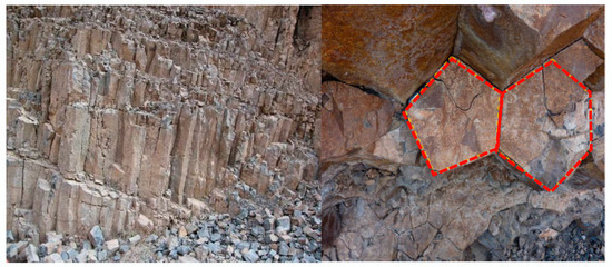
Figure 1.
Baihetan columnar jointed basalt.
The constitutive relation of conventional jointed rock masses is usually determined by the equivalent continuous method, which is the extension of a single set to multiple sets of jointed rock masses, after which a continuous and homogeneous equivalent jointed rock mass model can be obtained. Some related research has previously been conducted; for example, Morcland [7] established an equivalent continuous constitutive model derived for rock masses with a set of uniformly-spaced joints. Amadei [8] utilized a rock mass model based on three sets of orthogonal joints; the entire jointed rock mass was assumed to be an equivalent anisotropic continuum, and a closed solution of the constitutive model was obtained under uniaxial compression and hydrostatic isobaric conditions. Gerrard [9] considered the conditions of one, two, and three sets of orthogonal joints, and an equivalent elastic constitutive model of a homogeneous orthogonal rock mass was obtained by treating the rock mass and joints as isotropic bodies. Fossum [10] considered a rock mass with random joints and regarded the joints as one-dimensional deformation elements and the rock mass as a three-dimensional continuous medium. The isotropic elastic constitutive relation of a randomly jointed rock mass was obtained by an equivalent homogeneous method. Chang et al. [11] established an equivalent constitutive model of rock masses containing joints of any number of groups, directions, and spacings based on the sand slip theory. A constitutive model was proposed by Cai et al. [12] that could consider a wide variety of joint distributions in rock masses. Wang et al. [13] focused on rock masses with multiple sets of ubiquitous joints and established a mathematical model and an associated numerical implementation method that accounted for the anisotropy in both strength and deformation induced by the existence of joints. Agharazi et al. [14] established a three-dimensional constitutive model via the deformation analysis of jointed rock masses containing up to three joint sets with arbitrary spatial configurations. Xu et al. [15] proposed a new elastic-plastic constitutive model for jointed rock masses that can consider the persistence ratio at different visual angles and the anisotropic increase of plastic strain. Later, Zhang et al. [16,17] and Shi et al. [18] established a damage constitutive model via a combination of theoretical tests.
Columnar jointed basalt is rarely encountered in domestic and foreign projects, and research on its constitutive model has been seldom reported. In recent years, based on the Baihetan Hydropower Station on the Jinsha River, studies on the anisotropic characteristics of the mechanics of columnar jointed rock masses have been carried out by some scientific research institutes, and some achievements have been made regarding the development of a constitutive model of columnar jointed rock masses. For example, Meng [19] regarded the columnar jointed rock mass as a two-element structure composed of both rocks and jointed planes and deduced an equivalent anisotropic elastic constitutive model of a regular six-prism columnar-jointed rock mass via composite material mechanics. Di et al. [20] established a transverse isotropic constitutive model for columnar jointed rock masses by taking into account the dislocation zone in the jointed layer, the column axial deflection, and other factors. By introducing the theory of nonlinear fracture mechanics, Yan et al. [21] deduced an anisotropic constitutive model of columnar jointed rock masses via the theory of fracture energy. These research results have provided the basis for a constitutive model of columnar-jointed rock masses and their mechanical parameters. However, rock mass materials do not completely conform to the ideal assumed state, and, no matter how perfect a constitutive model is, it cannot fully take into consideration all the influencing factors; its applicability is simply reflected on the basis of mechanical properties and geological engineering laws. For the excavation of a chamber in a jointed rock mass, the conventional equivalent continuous theory fails to consider the influence of local bending stress, which results in large errors in the soft mechanical characteristics calculated by the model [22,23,24].
In 1909, the Cosserat brothers proposed the couple stress theory, which is also known as the Cosserat theory [25]. In the late 1980s, the Cosserat theory was first applied in the field of geotechnical engineering. It considers the inhomogeneity of the stress gradient in rock masses due to the existence of joint surfaces, and the calculation results are therefore more consistent with the deformation and failure phenomena that exist in practical applications. In recent decades, the Cosserat theory has received extensive attention, and its application has yielded substantial research progress. Muhlhaus [26,27,28,29] has attained the most outstanding achievements; his work involves layered rock masses, jointed rock masses, layered semi-infinite soil masses, rock coal, and gravel, among other materials. Chen et al. [30] and She et al. [31] extended the Cosserat plane problem to three dimensions. Yang and Li [32] proposed a new expanded Cosserat medium constitutive model for layered rock masses that takes into account the meso-displacement coordination between two layers with mismatched mechanical properties. This model can be used to analyze the elastic–plastic characteristics of composite rock masses composed of alternating hard and soft phases. Zhu et al. [33] deduced an equivalent continuous anisotropic constitutive model of macro jointed rock masses based on micro-media points for regular triangular and quadrangular prisms. The existing research demonstrates that the use of the Cosserat theory is superior for the analysis of the mechanical properties of joints and layered rocks, and it can better simulate the characteristics of the sliding and bending deformation of rock masses.
In view of this, in the present study, a constitutive model of discontinuous columnar jointed rock masses is developed based on the Cosserat theory for the irregular columnar jointed rock mass that occurs naturally at the Baihetan dam. Regular hexagonal prismatic basalt is taken as the typical research object, the jointed rock mass is regarded as an equivalent Cosserat continuum, and a three-dimensional Cosserat constitutive model of the regular hexagonal columnar jointed rock mass is established. The model is then verified via numerical simulation and was found to more accurately reflect the mechanical properties of such rock masses.
2. Constitutive Model of a Columnar Jointed Rock Mass
2.1. Cosserat Equivalent Model of a Single Set of Intermittent Jointed Rock Masses
As illustrated in Figure 2, the regular six-prism columnar jointed rock mass is a periodically repeating hexagon on the cross-section of a vertical column axis. When the column axis is not deflected, the horizontal direction is regarded as the composition of three groups of intermittent joints with 60° angles and the spacing s.
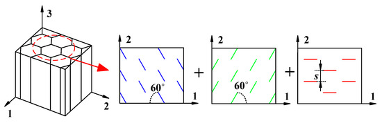
Figure 2.
Rock mass decomposition diagram of a six-prism columnar jointed rock mass.
Based on the Cosserat theory, a single-group Cosserat medium expansion model can first be derived, and a six-prism anisotropic constitutive model can then be obtained by the compound superposition method. The expression of the Cosserat elastic matrix of a single jointed rock mass is given as follows.
The single group of discontinuous jointed rock masses after decomposition illustrated in Figure 2 is simplified to obtain the model of a single group of jointed rock masses presented in Figure 3, where a is the joint, b is the complete rock with the same thickness, is the joint thickness, and is the joint communication rate. In the analysis, a and b are regarded as a composite element, and and respectively, represent the elastic modulus, Poisson’s ratio, and shear modulus of the composite element ab and the complete rock.
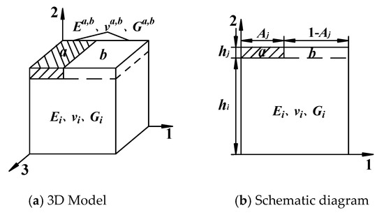
Figure 3.
Element model of a single set of intermittent jointed rock masses.
The Cosserat theory considers the action of couple-stress, and the asymmetric stress tensor and strain tensor (i, j = 1, 2) are adopted. There are three degrees of freedom in the micro-element studied by the Cosserat theory: two translational components, one rotational component, and the deformation components of stress and couple stress corresponding to the strain and curvature. According to the Cosserat medium point model of layered rock masses (Figure 4a), the single-group discontinuous jointed rock mass model illustrated in Figure 3 was extended, as presented in Figure 4b. Figure 4c shows the stress state of each layer when the unit body is affected by σ1.
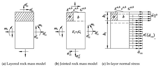
Figure 4.
Stress and couple stress on the equivalent model of the Cosserat element.
The stress and strain marked with the superscript “C” in Figure 4 refer to the stress and strain of Cosserat medium points, which represents the equivalent average of the corresponding quantity in the traditional continuous medium theory. Additionally, m1 is the couple stress. The sign convention in the case of plane strain is , . The following relationship was obtained by a previous study [34].
- ①
- Normal stress and normal strainwhere and are the average stress and strain of the composite element ab and the intact rock in 1 and 2 directions, respectively.
- ②
- Shear stress and shear strain
- ③
- Couple stress and curvaturewhere is the curvature, is the moment of inertia, , and and are the volume percentage; and .
After applying stress σ1 to the unit body illustrated in Figure 3, the equivalent elastic constant of the composite body ab can be obtained as follows [35].
Similarly, after applying stress σ2 to the unit body illustrated in Figure 3, the equivalent elastic constant of the composite body ab can be obtained as follows.
When the joint is regarded as an element without thickness, Equation (6) is . The stress applied to the element body in direction 2 is uniform; therefore, can be ignored. After substituting the equivalent elastic constant of compound element ab in Equations (5) and (6) into Equations (1)–(3), the asymmetric elastic matrix element of the Cosserat intermittent jointed rock mass can be described by Equation (7):
where is the shear modulus unique to the theory of the Cosserat medium [36]; . The joint stiffness and the tangential stiffness are often used to denote the joint elastic properties in engineering, while the Poisson effect of the joint surface and the stress along the length direction is neglected; . Equation (7) can then be written as Equation (8).
In this way, the Cosserat elastic matrix coefficients of a single group of intermittent jointed rock masses are obtained, and the elastic matrix coefficients of rock masses containing multiple sets of joints can be obtained by the stress–strain conversion formula. The derivation is subsequently developed.
2.2. Cosserat Elastic Matrix of a Hexagonal Prismatic Jointed Rock Mass
The columnar jointed rock mass in the project has lateral joint faces. The lateral joint spacing is set to s3, and the column axis is cut into the rock mass with a staggered distance, r. When the selected coordinate system does not follow the main direction of the intermittent jointed rock mass, the main axis of the material coordinate system 1-2 deviates from that of the natural coordinate system x-y by the angle θ, and the relationship between the two is shown in Figure 5.
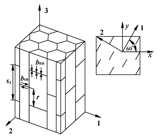
Figure 5.
Schematic diagram of the columnar joint of a regular hexagonal prism.
From the mechanics of composite materials, the off-axis transformed elastic coefficient matrix of a single group of intermittent jointed rock masses is given as follows:
where
Using the superposition principle, the equivalent elastic matrix of three sets of 60° intermittent jointed rock masses on the 1-2 plane of a hexagonal prism is given as follows:
where is the isotropic elastic matrix of the entire rock, and in a regular hexagon. After substituting each element of Equation (8) into Equation (11), the coefficients of the composite elastic matrix of the hexagonal prism are given as follows:
where and respectively represent the normal stiffness and tangential stiffness after compounding three groups of intermittent joints; .
The stress concentration is caused by the interlacing of the joints of a cylinder cut by transverse joints. Therefore, by referring to Section 2.1 and utilizing the stress concentration factor presented by Singh [37], the elastic matrix coefficients of the 1-3 plane are given as follows:
where and are the stress concentration factors caused by joint staggering (Figure 6), and and , respectively, represent the normal and tangential stiffness of the joint in 3 directions.
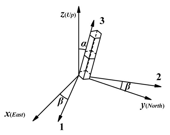
Figure 6.
Off-axis diagram of the columnar jointed rock mass (hexagonal prism).
Therefore, the three-dimensional Cosserat equivalent elastic matrix of a hexagonal columnar jointed rock mass is obtained as Equation (14):
where
3. Off-Axis Elastic Matrix Equation of a Columnar Jointed Rock Mass
3.1. Off-Axis Elastic Matrix Equation
Under actual geological conditions, the columnar jointed rock mass has a deflected material principal axis coordinate system and geodetic coordinate system. The deflected cylinder model is illustrated in Figure 6, in which x-y-z denotes the geodetic coordinate system, 1-2-3 denotes the material principal axis coordinate system, α denotes tendency, and β denotes trend.
The vector in the geodetic coordinate system x-y-z can be converted into the vector in the material principal axis coordinate system 1-2-3 by the equation .
Where
The tendency and trend are used to represent the transformation matrix [L] of the conversion of the material principal axis coordinate system 1-2-3 to the geodetic coordinate system x-y-z, which is given as
where
The elastic matrix of the geodetic coordinate system x-y-z of the columnar joint can be obtained by the transformation matrix [L] as follows.
3.2. Case Analysis
The columnar jointed rock mass of the diversion tunnel of the dam site area of the Baihetan Hydropower Station is mainly distributed in the P2β33−2 rock layer (basalt of the upper permian emeishan formation). The diameters of the columns range from 13 to 25 cm, and the length is generally 2–3 m; the average diameter and length are 0.2 and 2 m, respectively. The staggered distance is r = 0.5 m. Additionally, according to an engineering geology report, the occurrence of the P2β33−2 rock layer is 30° N~50° E, NE ∠ 10~25°, and the conversion matrix was obtained after taking the average value. The mechanical parameters of the rock mass and joint are listed in Table 1 [19].

Table 1.
Physical and mechanical parameters of the columnar jointed rock mass.
MATLAB software was used to compile the matrix calculation program. Additionally, via Equations (14) and (21), the equivalent elastic constants of the hexagonal prisms were obtained, and are listed in Table 2. The variations of the parameters of the columnar jointed rock mass with the dip angle are presented in Figure 7.
Table 2.
Off-axis equivalent elastic constants of a regular hexagonal prism.
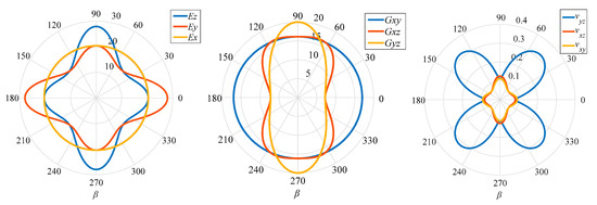
Figure 7.
Variations of the elastic parameters with the inclination angle β.
Based on the calculation results presented in Table 2 and Figure 7, when the column axis is not deflected, the mechanical properties in all directions are the same and show isotropy, i.e., the plane perpendicular to the column axis is an elastic symmetric plane. The six-prism columnar jointed rock mass can be simplified as a transversely isotropic body. When the hexagonal prism is deflected, because most of the elements in the conversion matrix are non-zero elements, the deflected elastic matrix changes accordingly, namely, from orthogonal anisotropy to general anisotropy, and the most typical expression is the asymmetry of the shear modulus. When the cylinder is deflected by 15°, considering the influence of the off-axis condition, and compared with the positive axis, E3 is reduced by 21.2%, E2 is reduced by 5.1%, and Poisson’s ratio and shear modulus also change by varying degrees. This indicates that the variation of each parameter is closely related to the occurrence of the column axis. Therefore, the influences of anisotropic parameters should be fully considered when analyzing the deformation and failure characteristics of a columnar jointed basalt diversion tunnel.
4. Program Implementation and Application of Constitutive Model
The internal joint fissures of the columnar joints are abnormally developed, and the deformation of the surrounding rock is significantly greater than that of underground tunnels with a similar depth and scale. In particular, under the action of excavation unloading, these joints are prone to slack and crack, and to form a ruptured structure. This is likely a substantial hidden danger to the normal operation of hydropower stations if sufficient attention is not paid to it. Based on the Cosserat anisotropic constitutive model, a numerical calculation program with multiple sets of joint surfaces was developed to investigate the deformation and failure of a columnar jointed rock mass tunnel after excavation.
4.1. Program Implementation of the Cosserat Constitutive Model
An important feature of the power of FLAC software is that it allows users to program the software themselves to apply constitutive models. There are two commonly used methods for this; one is the use of the built-in Fish language of FLAC, and the other is the use of the programming language VC++ to compile the model into a DLL file, which can be loaded whenever needed. This method endows custom constructed models with good versatility and scalability [38]. In this paper, the jointed rock mass is regarded as a kind of composite material that is composed of joints and rock masses. The advantage of this is that the material properties can be defined separately for joints and rock masses [39]. Three sets of mutually densely-cut joints were set according to the FLAC element type and included 1 set of transverse joints and 2 sets of vertical joints. Combined with the primary calculation methods of FLAC3D, the Cosserat anisotropic constitutive model was programmed by VC++ and compiled into the dynamic link library (DLL file), and was also embedded in the software to carry out the calculation of the columnar jointed rock mass.
Because the stress and strain tensors in FLAC3D numerical software are viewed as symmetric tensors, this work mainly considers the composite effect of joints and the rock mass; thus, the influence of the couple stress was neglected during programming. The calculation process of the Cosserat constitutive model is as follows. First, the basic mechanical parameters are input into the constitutive model function, and the strain increment of the current step element and the stress value of the previous step element are calculated. The steady-state strain and variable increment of the current time step of the element are calculated according to the stress value of the element. Then, based on the elastic assumption, the new stress of the element is calculated according to the elastic parameters, the elastic strain increment, and the element stress increment. The yield state of the element is judged by calling the element yield function, and the stress is adjusted according to the yield function and the plastic potential function to achieve new stress and yield states of the element. Finally, the new stress and related parameters of the element are returned to the main program of FLAC3D for the calculation of the next step and element. The final calculation results are obtained after this calculation process. According to the geological conditions of the Baihetan Hydropower Station, tunnel excavation was simulated to verify the correctness of the proposed Cosserat constitutive model and its application in underground engineering.
4.2. Model Establishment
The Baihetan Hydropower Station has five diversion tunnels. The average thickness of the overburden on the diversion tunnel is 256 m, and the cave type is a horseshoe. The calculation model of the diversion tunnel was simplified, and the dimensions of the model were as follows: length × width × height = 20 × 10 × 26 m, and the cavern was 4 m in width, the side walls were 4 m in height, and the arch was 2 m in height. The coordinate axis was taken at the center of the tunnel dome. The normal displacement is constrained in the lateral direction, and the deformation in three directions is constrained in the bottom boundary. The gravity of the overlying rock mass was uniformly applied to the top of the model, the value of which was about 2.4 MPa. The finite element calculation model is presented in Figure 8. The transversely isotropic model (Method 1) and the Cosserat anisotropic constitutive model (Method 2) were employed to simulate the mechanical behavior of the tunnel after excavation, and a comparative analysis was then carried. The mechanical parameters of the anisotropic constitutive model were selected according to the off-axis case described in Table 2.
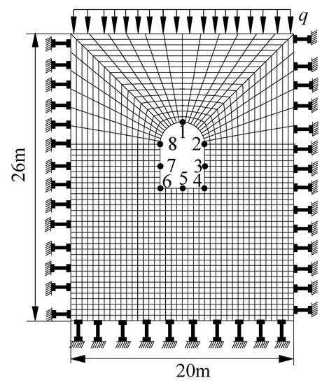
Figure 8.
Schematic diagram of the finite element calculation of the tunnel.
4.3. Result Analysis
Figure 9 and Figure 10 present the plastic zone and stress distribution after tunnel excavation as determined by the two calculation methods, from which it can be seen that, during the excavation of the rock mass, the principal stress difference increased with the redistribution of the stress field, which led to a plastic zone occurring within the surrounding rock, as well as the continuous increase of strain. Due to the lack of support measures after excavation, the failure of the surrounding rock of the tunnel was determined to be more serious by these two calculation methods. Via Method 1, the surrounding rock failure characteristics of the tunnel vaults and side walls, the range of the plastic zone, and the stress distribution were found to be roughly symmetrically distributed. This conforms to the distribution law of the plastic zone under an isotropic elastoplastic constitutive relation. The plastic zones of the vault and the side walls were distributed in the range of 0.4 to 0.5 times the width of the hole. Via Method 2, due to the existence of multiple sets of joint planes, the plastic zones and stress of the surrounding rock of the tunnel after excavation were found to be asymmetrically distributed. The plastic zones of the surrounding rock of the left and right wall were respectively 0.5 and 0.3 times the width of the hole. Additionally, the maximum plastic zone of the vault was distributed on the right side with a width of 0.3 times the hole. From the damage characteristics of the surrounding rock of the tunnel, the side walls and the vault were determined to mainly undergo shear failure by the two calculation methods, while the surrounding rock surface modeled by Method 2 had tensile damage. The reason for this is that, under the influence of two sets of vertical joint planes, the normal tension force was generated after the excavation unloading of the surrounding rock, which caused the joint surface to open and form a through-plane.
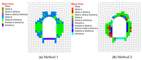
Figure 9.
Plastic zone distributions calculated by the two methods.
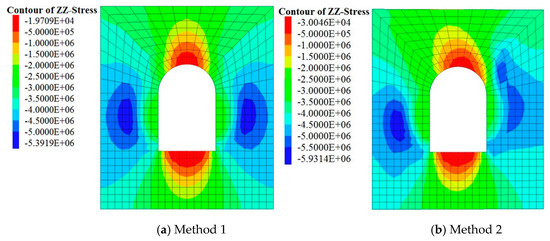
Figure 10.
Z-direction stress cloud maps calculated by the two methods.
The displacements of the top, bottom, and side walls of the tunnel were tracked and recorded, and the positions of the recording points are presented in Figure 8. Table 3 lists the displacement of each tracking point, as determined by the two methods. Each tracking point moved towards the inside of the tunnel, and the displacement values calculated by the two methods were very similar. The larger displacements were concentrated on the surface and moved along the free direction. The horizontal and vertical displacement values of points 2, 3, and 4 calculated by Method 1 were basically the same as those of points 6, 7, and 8, while the horizontal direction was opposite. In contrast, the horizontal and vertical displacement values of the symmetry points calculated by Method 2 were not consistent, and the horizontal displacement value of the left wall was generally greater than that of the right wall. On the excavation surface, the maximum vertical displacement determined by Method 2 was 2.62 mm, which was 28.3% greater than the value of 2.042 mm calculated by Method 1. The maximum horizontal displacement calculated by Method 2 was 1.26 mm, which was 79.0% greater than the value of 0.704 mm calculated by Method 1. According to this comparison, although the horizontal and vertical displacement values obtained by the two calculation methods were all on the same order of magnitude, the values calculated by Method 2 were generally greater than those calculated by Method 1.
Table 3.
Displacement values of each tracking point of the tunnel (unit: mm).
For the columnar jointed rock mass, although the calculation results of the two models were similar, the anisotropic model reflected that the rock mass deformation and damage were more significant. Moreover, the deformation calculation result of the anisotropic model was large and would be unsafe in practical engineering.
From the preceding comparison, it is evident that the Cosserat anisotropic constitutive model developed in this paper is more in line with the mechanical properties of the columnar jointed rock mass than the isotropic model, and clearly reflected its anisotropic characteristics.
5. Conclusions
The columnar basalt of the Baihetan Hydropower Station on the Jinsha River was taken as the research object to study an anisotropic constitutive model of the columnar jointed rock mass. The main conclusions can be drawn as follows.
- (1)
- By considering the rock and joint surfaces as dualistic structures, a Cosserat constitutive model of a regular hexagonal columnar jointed rock mass was established by analyzing the mechanical properties of three sets of intermittent joints angled at 60°.
- (2)
- The elastic matrix expression of the columnar jointed rock mass under an off-axis condition was given by introducing the positive off-axis transformation matrix. The equivalent anisotropic parameters under the off-axis condition were investigated by an example. The results showed that the elastic modulus decreases by 21.2% in the vertical direction and 5.1% in the horizontal direction when the cylinder is deflected by 15°. Additionally, Poisson’s ratio and shear modulus were also found to change significantly and revealed obvious anisotropy.
- (3)
- With the aid of the Visual C++ program development platform, a FLAC3D interface program of the proposed Cosserat constitutive model was developed, and the deformation and failure characteristics of a columnar joint tunnel after excavation were calculated and analyzed. The anisotropic constitutive model calculation program determined the deformation and failure phenomena of the surrounding rock of the tunnel to be more complex than those calculated by the isotropic model. The main manifestation is that the plastic zone and stress distribution of the surrounding rock are asymmetric. The vertical and horizontal displacements calculated by the Cosserat constitutive model were also greater than those calculated by the isotropic model. These findings all indicate that the calculation results of the Cosserat constitutive model could better reflect the mechanical properties of the columnar jointed rock mass after excavation. The research methods and conclusions of this paper can provide guidance for further construction at the Baihetan Hydropower Station.
- (4)
- The constitutive model derived in this work is based on the ideal state. Considering the more complicated geological conditions of the Baihetan Hydropower Station, the applicability of the model still requires further verification. In addition, the calculation program used in this work fails to consider other influencing factors, such as the couple stress and the joint dip angle, as well as what impact these factors will have on the tunnel excavation calculations. These issues are worthy of further research.
Author Contributions
Conceptualization, W.L., Z.Z. and C.Z.; software, W.L., Y.H., C.Z. and X.Q.; the final manuscript was written by W.L. and C.Z. All authors contributed to the discussion and analysis of the results regarding the final manuscript. All authors have read and agreed to the published version of the manuscript.
Funding
This research was funded by the National Natural Science Foundation of China (grant number 41831278, 51579081 and 51709184), the Postgraduate Research and Practice Innovation Program of Jiangsu Province (grant number 2017B703X14) and the Central Public-Interest Scientific Institution Basal Research Fund (grant number Y118008).
Conflicts of Interest
The authors declare that there are no conflict of interest regarding the publication of this paper.
References
- Ji, H.; Zhang, J.C.; Xu, W.Y.; Wang, R.B.; Wang, H.L.; Yan, L.; Lin, Z.N. Experimental Investigation of the Anisotropic Mechanical Properties of a Columnar Jointed Rock Mass: Observations from Laboratory-Based Physical Modelling. Rock Mech. Rock Eng. 2017, 50, 1919–1931. [Google Scholar] [CrossRef]
- Hao, X.J.; Feng, X.T.; Yang, C.X.; Jiang, Q.; Li, S.J. Analysis of EDZ Development of Columnar Jointed Rock Mass in the Baihetan Diversion Tunnel. Rock Mech. Rock Eng. 2016, 49, 1289–1312. [Google Scholar] [CrossRef]
- Hatzor, Y.H.; Feng, X.T.; Li, S.; Yagoda-Biran, G.; Quan, J.; Hu, L. Tunnel reinforcement in columnar jointed basalts: The role of rock mass anisotropy. Tunn. Undergr. Space Technol. 2015, 46, 1–11. [Google Scholar] [CrossRef]
- Chen, B.R.; Li, Q.P.; Feng, X.T.; Xiao, Y.X.; Feng, G.L.; Hu, L.X. Microseismic monitoring of columnar jointed basalt fracture activity: A trial at the Baihetan Hydropower Station, China. J. Seismol. 2014, 18, 773–793. [Google Scholar] [CrossRef]
- Xiao, W.; Deng, R.; Zhong, Z.; Fu, X.; Wang, C. Experimental study on the mechanical properties of simulated columnar jointed rock masses. J. Geophys. Eng. 2015, 12, 80–89. [Google Scholar] [CrossRef]
- Jie, C.; Quan, J.; Feng, X.; Li, S.; Liu, J.; Chen, W.; Zhang, J.; Pei, S. Insights into statistical structural characteristics and deformation properties of columnar jointed basalts: Field investigation in the Baihetan Dam base, China. Bull. Eng. Geol. Environ. 2018, 77, 775–790. [Google Scholar]
- Morcland, L.W. Elastic anisotropy of regularly jointed media. Rock Mech. 1976, 8, 49–53. [Google Scholar] [CrossRef]
- Amadei, B. Importance of anisotropy when estimating and measuring in situ stresses in rock. In International Journal of Rock Mechanics and Mining Sciences & Geomechanics Abstracts; Pergamon: Oxford, UK, 1996; Volume 33, pp. 293–325. [Google Scholar]
- Gerrard, C.M. Elastic Models of Rock Masses Having One, Two and Three Sets of Joints. In International Journal of Rock Mechanics and Mining Sciences & Geomechanics Abstracts; Pergamon: Oxford, UK, 1982; Volume 19, pp. 15–23. [Google Scholar]
- Fossum, A.F. Effective elastic properties for a randomly jointed rock mass. In International Journal of Rock Mechanics and Mining Sciences & Geomechanics Abstracts; Pergamon: Oxford, UK, 1985; Volume 22, pp. 467–470. [Google Scholar]
- Chang, C.S.; Misra, A.; Weeraratne, S.P. Deformation analysis of sands in cubical and hollow cylinder devices. Int. J. Numer. Anal. Methods Geomech. 1989, 13, 493–510. [Google Scholar] [CrossRef]
- Cai, M.; Horii, H. A constitutive model of highly jointed rock masses. Mech. Mater. 1992, 13, 217–246. [Google Scholar] [CrossRef]
- Wang, T.T.; Huang, T.H. A constitutive model for the deformation of a rock mass containing sets of ubiquitous joints. Int. J. Rock Mech. Min. Sci. 2009, 46, 521–530. [Google Scholar] [CrossRef]
- Agharazi, A.; Martin, C.D.; Tannant, D.D. A three-dimensional equivalent continuum constitutive model for jointed rock masses containing up to three random joint sets. Geomech. Geoengin. 2012, 7, 227–238. [Google Scholar] [CrossRef]
- Xu, Q.; Chen, J.; Li, J.; Zhao, C.; Yuan, C. Study on the Constitutive Model for Jointed Rock Mass. PLoS ONE 2015, 10, e0121850. [Google Scholar] [CrossRef] [PubMed]
- Zhang, C.; Zhu, Z.; Zhu, S.; He, Z.; Zhu, D.; Liu, J.; Meng, S. Nonlinear Creep Damage Constitutive Model of Concrete Based on Fractional Calculus Theory. Materials 2019, 12, 1505. [Google Scholar] [CrossRef] [PubMed]
- Zhu, Z.; Zhang, C.; Meng, S.; Shi, Z.; Tao, S.; Zhu, D. A Statistical Damage ConstitutieModel Based on the Weibull Distribution for Alkali-Resistant Glass FiberReinforced Concrete. Materials 2019, 12, 1908. [Google Scholar] [CrossRef] [PubMed]
- Shi, Z.Y.; Wang, Q.B.; Xu, L. Experimental Study of Cement Alkali-Resistant Glass Fiber (C-ARGF) Grouting Material. Materials 2020, 13, 605. [Google Scholar] [CrossRef] [PubMed]
- Guotao, M. Geomechanical Analysis of Anisotropic Columnar Jointed Rock Mass and Its Application in Hydropower Engineering. Ph.D. Thesis, Hohai University, Nanjing, China, 2007. [Google Scholar]
- Di, S.J.; Xu, W.Y.; Wang, W.; Shi, A.C. Transversely isotropic constitutive properties of a columnar jointed rock mass. J. China Univ. Min. Technol. 2011, 40, 881–887. [Google Scholar]
- Yan, D.X.; Xu, W.Y.; Wang, W.; Shi, C.; Shi, A.C.; Wu, G.Y. Research of size effect on equivalent elastic modulus of columnar jointed rock mass. Chin. J. Geotech. Eng. 2012, 34, 243–250. [Google Scholar]
- Forest, S.; Pradel, F.; Sab, K. Asymptotic analysis of heterogeneous Cosserat media. Int. J. Solids Struct. 2001, 38, 4585–4608. [Google Scholar] [CrossRef]
- Forest, S.; Barbe, F.; Cailletaud, G. Cosserat modelling of size effects in the mechanical behavior of polycrystals and multi-phase materials. Int. J. Solids Struct. 2000, 37, 7105–7126. [Google Scholar] [CrossRef]
- Iordache, M.M.; Willam, K. Localized failure analysis in elastoplastic Cosserat continua. Comput. Methods Appl. Mech. Eng. 1998, 151, 559–586. [Google Scholar] [CrossRef]
- Cosserat, E.; Cosserat, F. Théorie des Corps Déformables; A. Hermann et Fils: Paris, France, 1909. [Google Scholar]
- Mühlhaus, H.B.; Vardoulakis, I. The thickness of shear bands in granular materials. Geotechnique 1987, 37, 271–283. [Google Scholar] [CrossRef]
- Mühlhaus, H.B. Application of Cosserat theory in numerical solutions of limit load problems. Ingenieur-Archiv 1989, 59, 124–137. [Google Scholar] [CrossRef]
- Dai, C.; Mühlhaus, H.; Meek, J.; Duncan Fama, M. Modelling of blocky rock masses using the Cosserat method. Int. J. Rock Mech. Min. Sci. Geomech. Abstr. 1996, 33, 425–432. [Google Scholar] [CrossRef]
- Mühlhaus, H.B. Stress and couple stress in a layered half plane with surface loading. Int. J. Numer. Anal. Methods Geomech. 2010, 14, 545–563. [Google Scholar] [CrossRef]
- Jun, L.; Shenghong, C. Three-dimensional Elastic Couple-stress Theory of Jointed Rock Mssses. Rock Soil Mech. 1995, 4, 20–29. [Google Scholar]
- Chenxue, S.; Wenlin, X.; Shenhong, C. Cosserat Medium Analysis of Deformation of Layered Rockmass with Bending Effects. Rock Soil Mech. 1994, 15, 20–29. [Google Scholar]
- Li, Y.P.; Yang, C.H. Three-dimensional expanded Cosserat medium constitutive model for laminated salt rock. Rock Soil Mech. 2006, 27, 509–513. [Google Scholar]
- Zhende, Z.; Tianhao, Q.; Shihong, W.; Lianguo, W.; Linzhu, S. Study of Anisotropic Constitutive Model of Columnar Jointed Rock Masses Based On Cosserat Theory. Chin. J. Rock Mech. Eng. 2010, 29, 4068–4076. [Google Scholar]
- Yang, C.H.; Li, Y.P. Expanded Cosserat Medium Constitutive Model Forlaminated Salt Rock. Chin. J. Rock Mech. Eng. 2005, 24, 4226–4232. [Google Scholar]
- Shilin, Y.; Yuying, H.; Chuanyao, C. An Equivalent Model for Jointed Rock Mass with Planar Nonpenetrative Joint and Its Elastic Parameters. J. Huazhong Univ. Sci. Technol. 2001, 29, 64–67. [Google Scholar]
- Chenxue, S.; Jixian, L.; Yuzen, Z. The Research on the Second Shear Modulus GC in Cosserat Medium Theory of Layered Rockmas. Rock Soil Mech. 1996, 4, 62–69. [Google Scholar]
- Singh, B. Continuum characterization of jointed rock masses. Part I—The constitutive equations. In International Journal of Rock Mechanics and Mining Sciences & Geomechanics Abstracts; Pergamon: Oxford, UK, 1972; Volume 10, pp. 337–349. [Google Scholar]
- Itasca Consulting Group. Fast Lagrangian Analysis of Continua in 3 Dimensions; Itasca Consulting Group: Minneapolis, MN, USA, 2002. [Google Scholar]
- Zhu, D.J.; Yang, L.D.; Cai, Y.C. Mixed multi-weakness plane softening model for jointed rock mass. Chin. J. Geotech. Eng. 2010, 32, 185–191. [Google Scholar]
© 2020 by the authors. Licensee MDPI, Basel, Switzerland. This article is an open access article distributed under the terms and conditions of the Creative Commons Attribution (CC BY) license (http://creativecommons.org/licenses/by/4.0/).