FPGA Implementation and Design of a Hybrid Chaos-AES Color Image Encryption Algorithm

Abstract
1. Introduction
2. Algorithm Design
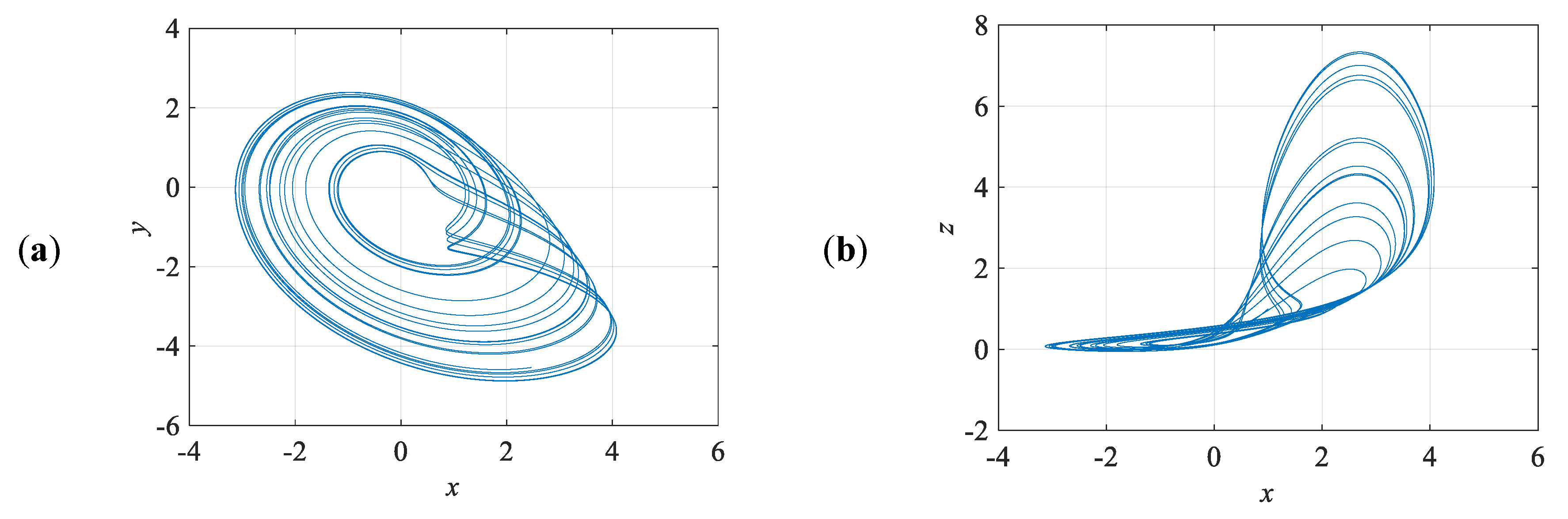
2.1. Chaotic System
2.2. Purpose of New Chaotic Encryption Algorithm
- i.
- AddRoundKey: Each byte in the matrix uses XOR to manipulate the round key; a subkey is derived from the main key using Rijndael’s key schedule.
- ii.
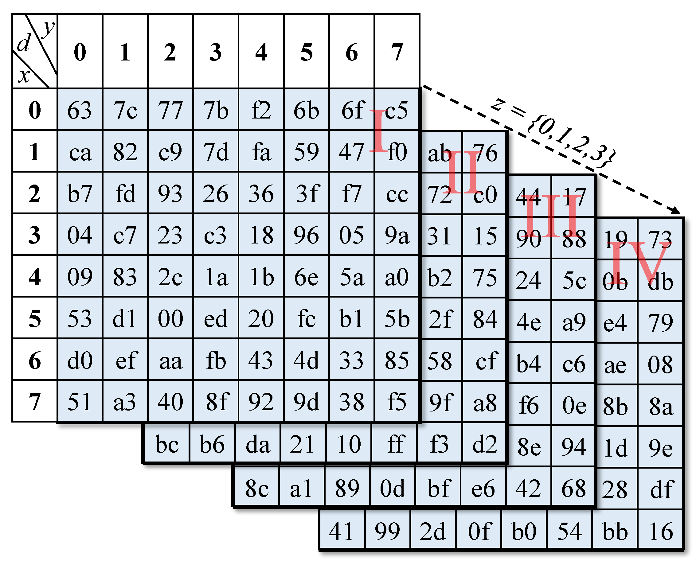
- SubBytes: Change each byte using an 8-bit substitution box. This step provides the nonlinear substitution of the replacement function.
- iii.
- ShiftRows: In the ShiftRows step, bytes in each row of the state are shifted cyclically to the left. The shifted number of places each byte is depended on the number of rows.
- iv.
- MixColumns: In order to properly mix linear operations in a matrix, this step uses a linear transformation to mix four bytes per line. The last encryption loop omits the MixColumns step and replaces it with another AddRoundKey.
- Step. i.
- In the Spin-Sort, we can express the plaintext as a 4 × 4 matrix in Figure 5a. Where x0, x1, x2, …, x15 are 8-bit values.
- Step. ii.
- Mark the matrix as an outer and inner blocks as Figure 5b.
- Step. iii.
- Take a vertex of the outer(inner) block as the root.
- Step. iv.
- Sorted by the root, clockwise (counterclockwise) from the outer (inner) block to the inner (outer) block.
2.3. Key Generator Design
- Step. i.
- Select the proper values to be the initial conditions for the 4D chaotic system.
- Step. ii.
- Execute pre-iteration nr rounds, where nr is 2000 rounds.
- Step. iii.
- Calculate summation of image pixel, according to Equation (6).where m and n are the image dimension, Pixel(i, j) is the i row and j column pixel unsigned values of plain image.
- Step. iv.
- Use Sumpixel as parameter to iterate np rounds as in Equation (7).
- Step. v.
- The initial 128-bit key generate after iterate np rounds in 4D chaotic system as Equation (8).
- Step. vi.
- Iterate once every 16-byte block encryption.
2.4. Flow Chart of Encryption
3. FPGA Implementation
3.1. Chaos System Discretization
3.2. Encryption System Hardware Implementation
3.2.1. SDRAM Access
3.2.2. Encryption System
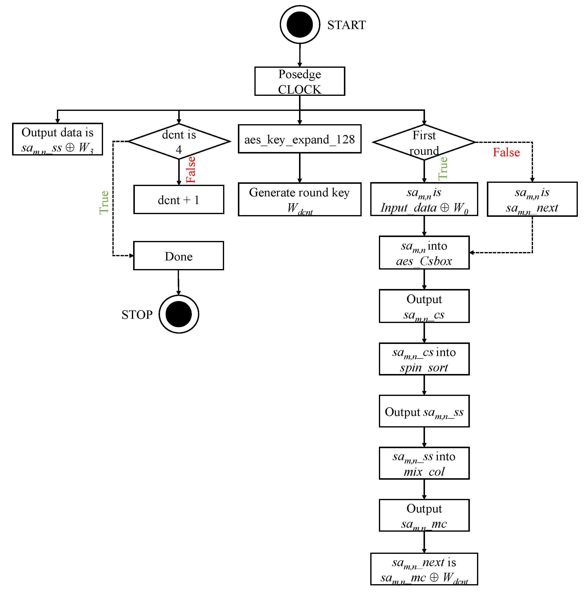
- Step. i.
- Posedge clock, count a register dcnt to confirm if the number of rounds is 4.
- Step. ii.
- Posedge clock, module aes_key_expand_128 generate new round key.
- Step. iii.
- Posedge clock, check whether is initial round. If is initial round, registers sam,n are divided 128-bits input data XOR first round key, Else, assign by sam,n_next which is sam,n_mc XOR round key,
- Step. iv.
- Wire connected module aes_Csbox, spin_sort and mix_col. The module aes_Csbox produced sam,n_cs, the module spin_sort produced sam,n_ss, the module mix_col produced sam,n_mc.
- Step. v.
- Posedge clock, the output data is assigned sam,n_ss XOR round key.
4. Security Analyisis
4.1. Histogram Analysis
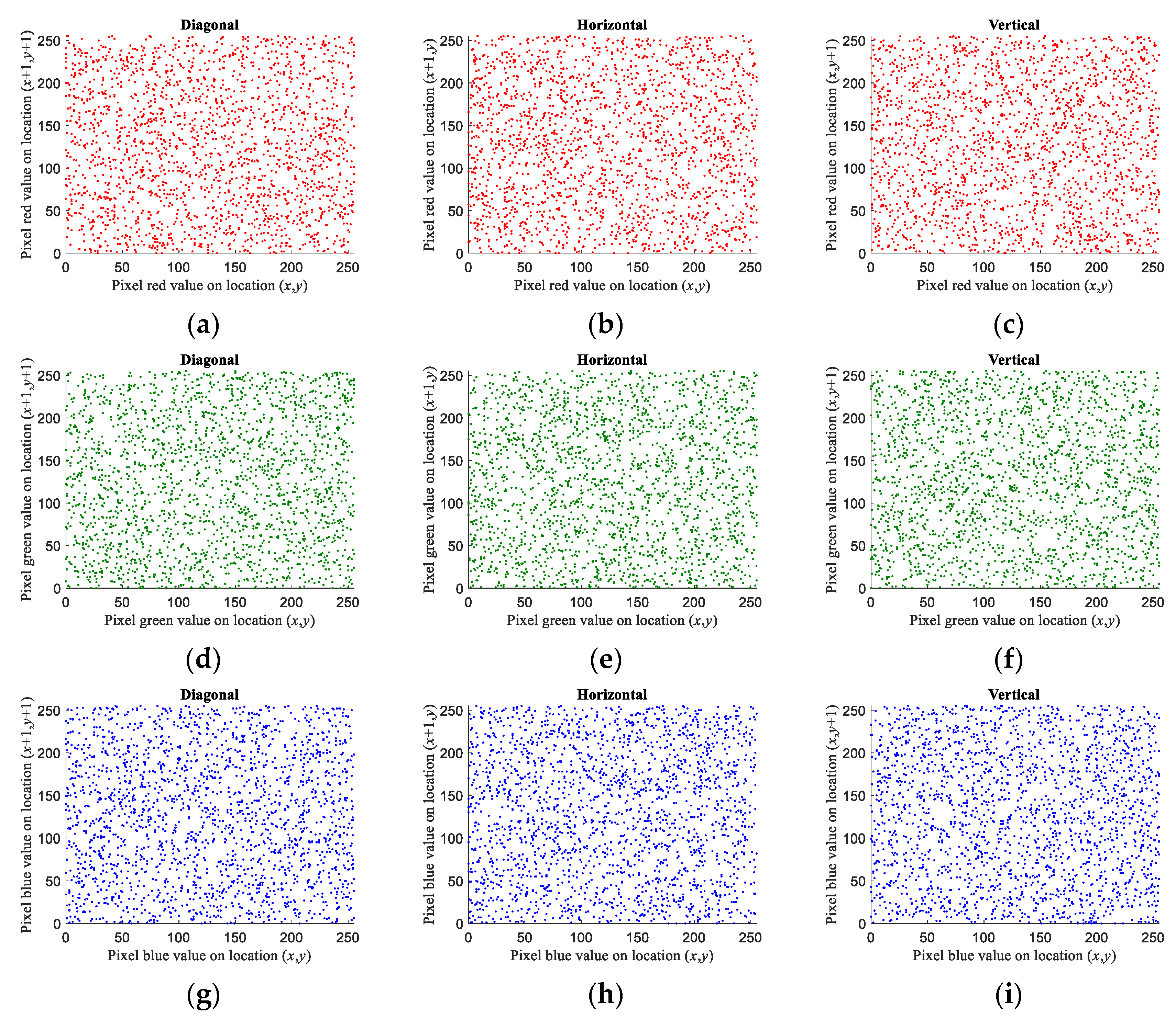
4.2. Correlation Analysis
4.3. Differential Attack Analysis
4.4. Information Entropy Analysis
5. Conclusions
Author Contributions
Funding
Conflicts of Interest
References
- Wu, J.; Liao, X.; Yang, B. Color image encryption based on chaotic systems and elliptic curve ElGamal scheme. Signal Process. 2017, 141, 109–124. [Google Scholar] [CrossRef]
- Amigo, J.M.; Kocarev, L.; Szczepanski, J. Theory and practice of chaotic cryptography. Phys. Lett. A 2007, 366, 211–216. [Google Scholar] [CrossRef]
- Jakimoski, G.; Kocarev, L. Chaos and cryptography: Block encryption ciphers based on chaotic maps. IEEE Trans. Circuits Syst. I Fundam. Theory Appl. 2001, 48, 163–169. [Google Scholar] [CrossRef]
- Matthews, R. On the Derivation of a “Chaotic” Encryption Algorithm. Cryptologia 1989, 13, 29–42. [Google Scholar] [CrossRef]
- Fridrich, J. Symmetric ciphers based on two–dimensional chaotic maps. Int. J. Bifurc. Chaos 1998, 8, 1259–1284. [Google Scholar] [CrossRef]
- Pareschi, F.; Setti, G.; Rovatti, R. Implementation and testing of high-Speed CMOS true random number generators based on chaotic systems. IEEE Trans. Circuits Syst. I Regul. Pap. 2010, 57, 3124–3137. [Google Scholar] [CrossRef]
- Özkaynak, F. Cryptographically secure random number generator with chaotic additional input. Nonlinear Dyn. 2014, 78, 2015–2020. [Google Scholar] [CrossRef]
- Yen, J.-C.; Guo, J.-I. Efficient hierarchical chaotic image encryption algorithm and its VLSI realization. IEEE Proc. Vis. Image Signal Process. 2000, 147, 167–175. [Google Scholar] [CrossRef]
- Shannon, C.E. Communication theory of secrecy systems. Bell Labs Tech. J. 1949, 28, 656–715. [Google Scholar] [CrossRef]
- Cao, C.; Sun, K.; Liu, W. A Novel Bit-Level Image Encryption Algorithm Based on 2D-LICM Hyperchaotic Map. Signal Process. 2018, 143, 122–133. [Google Scholar] [CrossRef]
- Yin, Q.; Wang, C. A New Chaotic Image Encryption Scheme Using Breadth-First Search and Dynamic Diffusion. Int. J. Bifurc. Chaos 2018, 28, 1850047. [Google Scholar] [CrossRef]
- Zhang, Y. The unified image encryption algorithm based on chaos and cubic S-Box. Inf. Sci. 2018, 450, 361–377. [Google Scholar] [CrossRef]
- Wang, X.; Zhao, Y.; Zhang, H.; Guo, K. A novel color image encryption scheme using alternate chaotic mapping structure. Opt. Lasers Eng. 2016, 82, 79–86. [Google Scholar] [CrossRef]
- Norouzi, B.; Mirzakuchaki, S. A fast color image encryption algorithm based on hyper-chaotic systems. Nonlinear Dyn. 2014, 78, 995–1015. [Google Scholar] [CrossRef]
- Boriga, R.; Dăscălescu, A.C.; Priescu, I. A new hyperchaotic map and its application in an image encryption scheme. Signal Process. Image Commun. 2014, 29, 887–901. [Google Scholar] [CrossRef]
- Wu, Y.; Zhou, Y.; Saveriades, G.; Agaian, S.; Noonan, J.P.; Natarajan, P. Local Shannon entropy measure with statistical tests for image randomness. Inf. Sci. 2013, 222, 323–342. [Google Scholar] [CrossRef]
- Bhatnagar, G.; Wu, Q.M.J. Biometric Inspired Multimedia Encryption Based on Dual Parameter Fractional Fourier Transform. IEEE Trans. Syst. Man Cybern. Syst. 2014, 44, 1234–1247. [Google Scholar] [CrossRef]
- Mandal, M.K.; Kar, M.; Singh, S.K.; Barnwal, V.K. Symmetric key image encryption using chaotic Rossler system. Secur. Commun. Netw. 2013, 7, 2145–2152. [Google Scholar] [CrossRef]
- Chandrasekaran, J.; Subramanyan, B.; Selvanayagam, R. A Chaos Based Approach for Improving Non Linearity in S Box Design of Symmetric Key Cryptosystems. In Proceedings of the International Conference on Computer Science and Information Technology CCSIT 2011, Bangalore, India, 2–4 January 2011; pp. 516–522. [Google Scholar]
- SunSun, K. Chaotic Secure Communication: Principles and Technologies; De Gruyter Gruyter: Berlin, Germany, 2016. [Google Scholar]
- Pak, C.; Huang, L. A New Color Image Encryption Using Combination of the 1D Chaotic Map. Signal Process. 2017, 138, 129–137. [Google Scholar] [CrossRef]
- Wu, X.; Zhu, B.; Hu, Y.; Ran, Y. A novel colour image encryption scheme using rectangular transform-enhanced chaotic tent maps. IEEE Access 2017, 5, 6429–6436. [Google Scholar] [CrossRef]
- Wang, X.; Zhang, H.-L. A color image encryption with heterogeneous bit-permutation and correlated chaos. Opt. Commun. 2015, 342, 51–60. [Google Scholar] [CrossRef]
- Niyat, A.Y.; Moattar, M.H.; Torshiz, M.N. Color image encryption based on hybrid hyper-chaotic system and cellular automata. Opt. Lasers Eng. 2017, 90, 225–237. [Google Scholar] [CrossRef]
- Wu, Y.; Noonan, J.P.; Agaian, S. NPCR and UACI randomness tests for image encryption. Cyber J. Multidiscip. J. Sci. Technol. J. Sel. Areas Telecommun. 2011, 1, 31–38. [Google Scholar]
- Yang, C.-H.; Wu, H.-C.; Su, S.-F. Implementation of Encryption Algorithm and Wireless Image Transmission System on FPGA. IEEE Access 2019, 7, 50513–50523. [Google Scholar] [CrossRef]
- Wang, X.-Y.; Zhang, Y.-Q.; Bao, X.-M. A Colour Image Encryption Scheme Using Permutation-Substitution Based on Chaos. Entropy 2015, 17, 3877–3897. [Google Scholar] [CrossRef]


| IP-CORE | Time Latency (Clock, 50 MHz) |
|---|---|
| ALTFP_ADD | 8 |
| ALTFP_SUB | 8 |
| ALTFP_MULT | 6 |
| Lena | Airplane | Pepper | Mandrill | |
|---|---|---|---|---|
| Diagonal | −0.000483 | 0.000348 | 0.000759 | −0.000042 |
| Horizontal | −0.001001 | 0.000468 | 0.000466 | 0.000613 |
| Vertical | −0.001015 | 0.001086 | −0.000803 | 0.002013 |
| Proposed | Ref. [22] | Ref. [23] | Ref. [24] | |
|---|---|---|---|---|
| Diagonal | −0.000546 | 0.000573 | 0.006000 | 0.000700 |
| Horizontal | −0.000383 | 0.000538 | −0.012700 | 0.004900 |
| Vertical | −0.001287 | −0.007058 | 0.006700 | 0.003100 |
| Proposed | Ref. [22] | Ref. [23] | Ref. [24] | |
|---|---|---|---|---|
| Diagonal | −0.003829 | −0.001693 | −0.007800 | 0.001700 |
| Horizontal | 0.001205 | 0.001186 | −0.007500 | 0.005400 |
| Vertical | −0.000961 | 0.000177 | −0.006800 | 0.000100 |
| Proposed | Ref. [22] | Ref. [23] | Ref. [24] | |
|---|---|---|---|---|
| Diagonal | 0.002926 | −0.000927 | 0.002600 | 0.000700 |
| Horizontal | −0.003825 | −0.002372 | −0.000700 | 0.005300 |
| Vertical | −0.000798 | 0.007818 | 0.004200 | 0.002200 |
| Proposed | Ref. [22] | Ref. [23] | Ref. [24] | |
|---|---|---|---|---|
| Lena | 99.6040% | 99.71% | 99.6150% | 99.6525% |
| Airplane | 99.6051% | NaN | NaN | NaN |
| Pepper | 99.6227% | 99.74% | 99.6156% | 99.6254% |
| Mandrill | 99.6071% | 99.72% | 99.6031% | 99.6378% |
| Proposed | Ref. [22] | Ref. [23] | Ref. [24] | |
|---|---|---|---|---|
| Lena | 33.4614% | 33.45% | 33.4893% | 33.4331% |
| Airplane | 33.4503% | NaN | NaN | NaN |
| Pepper | 33.5029% | 33.53% | 33.4336% | 33.4566% |
| Mandrill | 33.4969% | 33.50% | 33.4392% | 33.4673% |
© 2020 by the authors. Licensee MDPI, Basel, Switzerland. This article is an open access article distributed under the terms and conditions of the Creative Commons Attribution (CC BY) license (http://creativecommons.org/licenses/by/4.0/).
Share and Cite
Yang, C.-H.; Chien, Y.-S. FPGA Implementation and Design of a Hybrid Chaos-AES Color Image Encryption Algorithm. Symmetry 2020, 12, 189. https://doi.org/10.3390/sym12020189
Yang C-H, Chien Y-S. FPGA Implementation and Design of a Hybrid Chaos-AES Color Image Encryption Algorithm. Symmetry. 2020; 12(2):189. https://doi.org/10.3390/sym12020189
Chicago/Turabian StyleYang, Cheng-Hsiung, and Yu-Sheng Chien. 2020. "FPGA Implementation and Design of a Hybrid Chaos-AES Color Image Encryption Algorithm" Symmetry 12, no. 2: 189. https://doi.org/10.3390/sym12020189
APA StyleYang, C.-H., & Chien, Y.-S. (2020). FPGA Implementation and Design of a Hybrid Chaos-AES Color Image Encryption Algorithm. Symmetry, 12(2), 189. https://doi.org/10.3390/sym12020189