1. Introduction
Structural sandwich panels usually consist of three main parts: two thin, stiff and strong faces separated by a relatively thick, light core. The faces are adhesively bonded to the core. The sandwich composite is a structural element with excellent thermal insulation, a very high stiffness to weight ratio and a high bending strength to weight ratio [
1,
2]. Currently, it is difficult to imagine civil engineering, particularly industrial engineering, without sandwich panels. These panels are mainly used as building envelop (walls, roofs), partition walls, and suspended ceilings.
Sandwich panels usually work in simple support and load conditions, in which bending combined with shear dominates. However, more and more often, practical issues appear in which torsion also plays an important role. The example, in which torsion is important, is the installation of an additional façade layer to the existing walls made of horizontally mounted sandwich panels. The heavier and more distant the additional layer, the larger the torsion.
The problem of sandwich plates torsion was intensively investigated about 50 years ago. Seide [
3] considered Saint-Venant torsion of rectangular sandwich plates and derived the expression for torsional stiffness. The same problem was analyzed by Cheng [
4], who presented two analyses: rigorous and simplified. Finally, a solution was obtained based on the Prandtl membrane analogy, which was in a good agreement with the Saint-Venant analysis. A different approach to the problem of free torsion was used by Stamm and Witte [
5]. The layered cross-section has been treated as a closed section, part of which is the core. A fairly similar approach, although somewhat simplified, was used by Höglund [
6], who used the formulas for the analysis of sandwich panels with openings.
Although it seemed that the publications on the subject of torsion of sandwich panels exhausted the subject, experimental studies carried out by Rädel and Lange [
7] showed that it is very different. It turned out that the stiffness determined according to Stamm and Witte [
5] and Höglund [
6] is approximately 40–60% higher than the torsional rigidity determined experimentally. What is more, stiffness according to Seide [
3] and Cheng [
4] is even 6–10 times higher. The practical significance of the problem can be demonstrated by the fact that in the official design recommendations CIB 378 [
8], equations are shown that are consistent with Stamm and Witte [
5] and Höglund [
6], with little reference to the importance of warping torsion.
For torsional behavior, it is very difficult to find models that accurately describe the behavior of complex cross-sections during twisting. A general composite bar with rectangular cross-section subjected to torsion was studied by Ahmadi [
9], where three-dimensional stress state was investigated. The twisting of laminate due to torsion torque were studied for various layers stacking. The elastic response of inhomogeneous orthotropic beams with general cross-section was investigated by Savoia and Tullini [
10]. The problem was formulated in terms of the warping and of the Prandtl stress function. This approach was extended to the case of very thin composite, rectangular cross-sections by Swanson [
11]. Many papers indicate that classical theories strongly underestimate the influence of the flexibility of the soft core on the deformations of the sandwich panel [
12,
13]. Therefore, much attention is paid to the correct determination of shear modules [
14,
15]. This is particularly important in torsion of sandwich elements with a complex and non-uniform core structure [
16]. The analytical expressions of the effective torsion stiffness coefficients for various types of composite beams, in terms of the three-dimensional parameters of the thin structure, were described by Bîrsan et al. [
17]. To demonstrate the accuracy of the developed theories and presented solutions, the experimental tests and even more frequently, numerical simulations are used [
18,
19].
The purpose of the work is to create a numerical model that will satisfactorily reflect the behaviour of the sandwich panel subjected to torsion. To simplify the presentation and interpretation of the results, the case of a single-span element is presented, to which a concentrated torque is applied. This case is of significant engineering importance. Performing numerical simulations, the influence of symmetrical boundary conditions on the structural response of twisted sandwich panel was examined. Results of numerical analyses were compared with the values obtained from the analytical beam model, in which warping (Vlasow) torsion is also taken into account. Differences in results are discussed in the context of the correct approach to the problem of twisting and the safety of the most commonly used analytical 1-D model.
3. Numerical Models
3.1. Basic Assumptions of the Numerical Models
All numerical models have been prepared in the Abaqus system. To accurately reflect the behaviour of the structure, all models are 3-D. The 3-D structure consists of two thin steel facings and a thick but flexible core. Geometrical parameters of the analyzed sandwich panel, such as the width, length of the plate, and the thickness of the individual components of the plate are in accordance with
Section 2.3 and
Figure 1.
The facings were modelled by using the four-node, reduced integration, and finite membrane strain, shell elements called the S4R. The integration rule through the thickness of the shell has been chosen as the Simpson’s rule (with the division of thickness into five points of integration). The core of the panel was modelled using eight-node linear brick, reduced integration C3D8R elements. Interaction between the facings and the core was assumed as a TIE type. The TIE connection means that all displacements and rotations of adjacent nodes of contacting parts are identical.
In the conducted research, the influence of the mesh size on the numerical results was examined. The issue is often reported in the literature [
21,
22]. The mesh-size was assumed as constant for all components of the model. Numerical calculations were started with the mesh-size equal to 20 mm. After reducing the mesh to 15 mm, the obtained stress and displacement results differed by almost 5%. Subsequent mesh compaction to 12.5 mm resulted in another change in the results, but the change did not exceed 1%. Therefore, the final mesh-size was chosen to be 12.5 mm.
For the steel facings, an isotropic, perfectly elastic model of material was assumed, for which the modulus of elasticity is
Ef = 210 GPa and Poisson ratio is
vf = 0.3. The core of the sandwich panel is made of polyurethane foam defined as elastic material by means of engineering constants:
It was decided to define the material parameters in this manner, because polyurethane foams do not meet the classic condition
G =
E/2(1 +
v) [
23]. By the way, it is worth noting that the stiffness of the foam plays an important role in the behavior of the entire structure.
3.2. Load Conditions
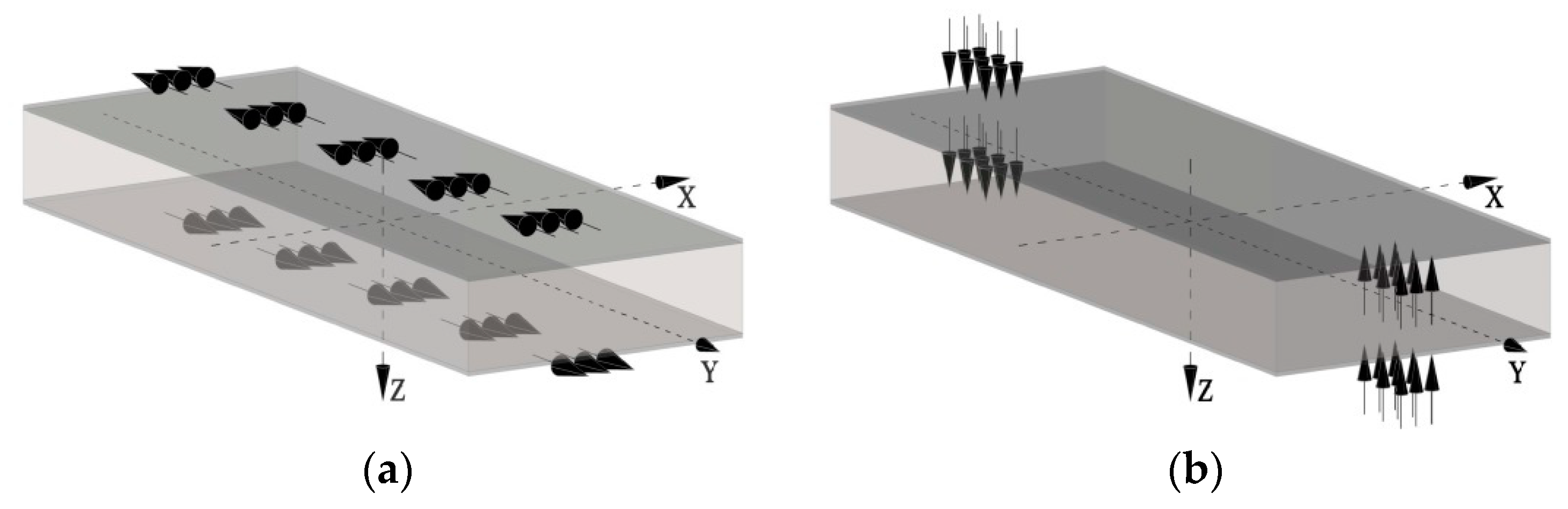
Our goal is to define load conditions that will correspond to the concentrated torque that was assumed in the analytical beam model. This is difficult because the load definition must match the model class (in this case 3-D). Two different load models were used that theoretically produce the same stresses and strains in the panel.
The first one is the uniform load tangential to the facings, distributed over the middle band of both facings (
Figure 2a). The width of the band was assumed as
w = 60 mm. The directions of the loads on both facings are opposite. The horizontal pair of resultant forces (uniform load tangential to the facings of
qy = 55.83 kN/m
2) creates the concentrated torsional moment equal to
M = 0.333 kNm. The second one is the vertical pair of loads, which generates the same value of torsional moment
M (
Figure 2b). The loads are applied to both facings as a uniform pressure (
qz = 30.86 kN/m
2) spread over area 60 × 100 mm. The loads are perpendicular to the facings and are opposite to each other. It is worth noting that the load cannot be defined as concentrated torsional moment in a single node because such a definition leads to unrealistic local stresses and deformations.
3.3. Support Conditions
The 3-D structure has total length of 4.06 m and is supported on both ends by rigid supporting plates, each 0.06 m wide. As a result, the span of the structure is 4.00 m. The supporting plates are tied with the facings of the sandwich structure. The boundary conditions were defined in the reference points located in the middle of the supporting plates.
It should be realized that in the analysis of a 3-dimensional structure, it is impossible to perfectly match the theoretical fork-support conditions used in the case of beam (i.e., 1-D element). From the other point of view, in the case of 3-D systems, we have many more possibilities and support conditions that may be more similar to reality. However, it should be remembered that it is much more difficult to predict the effects of introducing more complex support conditions (in fact, also loading conditions).
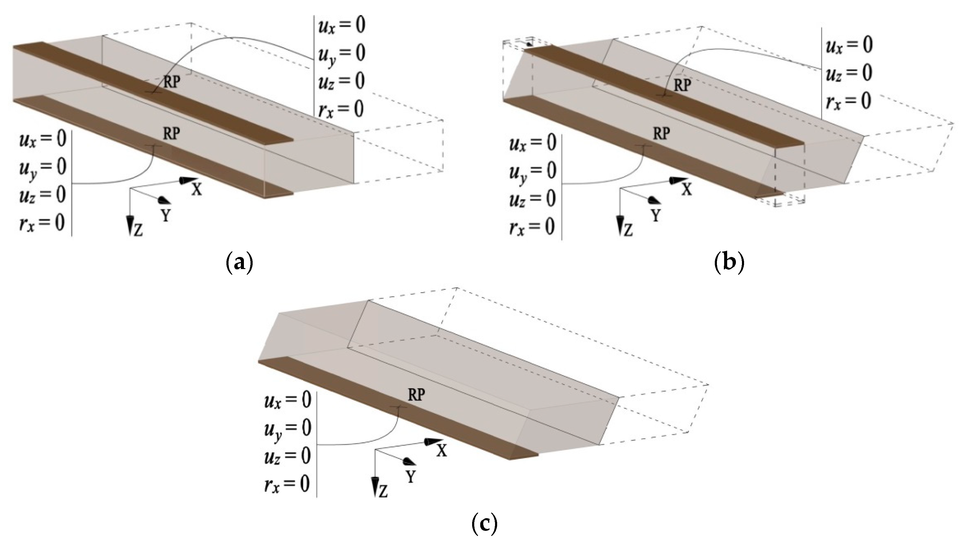
To analyse the influence of the boundary conditions on the structural behaviour of the sandwich panels subjected to torsion, three different support conditions were chosen. The boundary conditions were determined for the reference points (RP) of the rigid supporting plates. In all cases, the boundary conditions are symmetric—the same on both ends of the element. It should be emphasized that while choosing the support conditions, efforts have been made to approach the conditions specified for the beam.
In the first model, there are two supporting plates on each end of the panel: one below, and one above the sandwich element (
Figure 3a). Both supporting plates cannot move in the
y-direction. Support displacement in the
z-direction is equal to zero by blocking the displacement at the reference points in the
z-direction and the rotation around the
x-axis. In addition, the movement of reference points in the
x-direction is blocked, but the rotation around the
z-axis is free, thus the sandwich panel has the possibility of warping. The limitations of displacements in the
x-direction are the same in all models. The support reactions in the
x-direction are almost zero. It turned out that such a support model guarantees high compliance with the 1-D analytical model (see results presented in
Section 4).
The second support model differs from the first only in that there is no restriction on the displacement of the upper supporting plate in the
y-direction (
Figure 3b). Such a support model may be closer to reality because the fasteners that fix the panel to the support have a limited bending stiffness. It means a certain flexibility of the support in the
y-direction. In the case of the third support model, only the lower supporting plate was used (
Figure 3c). In this way, relatively high freedom of support movement was obtained.
4. Discussion of the Results
4.1. Description of the Models
The most important results of numerical analyses are shown below. In order to organize the presentation, the abbreviated names have been assigned to the described numerical models. The following shortcuts were used: HFP when the plate was loaded with a horizontal pair of forces and VFP when the vertical pair of forces were used to introduce the torsion moment. Various support conditions are indicated by the following abbreviations:
BC1—when two supporting plates were used on both ends of sandwich panel, while blocking the possibility of displacements in the direction of the
y-axis and
z-axis (
Figure 3a),
BC2—when two supporting plates were used on both ends of sandwich panel, while blocking the possibility of displacements in the direction of the
z-axis; only the bottom plates were blocked in the
y direction (
Figure 3b),
BC3—when only the bottom supporting plates were used on both ends of sandwich panel (
Figure 3c).
Using these symbols, the numerical models have ben appropriately described, for example as model BC1-HFP.
The obtained results of the numerical analyses (two types of load conditions, three types of support conditions) are presented in the form of graphs. The change of the following values along the sandwich panel is shown: vertical displacement of the bottom facing uf(z), normal stress in the bottom facing σf(xx), shear stress in the bottom facing τf(xy), and shear stress in the core τc(xz). Letters x, y, and z used in the subscript indicate the direction or the plane, which refers to the presented value. Symbols c and f denote core and facing, respectively. Due to the symmetry of the model, the graphs are made in the longitudinal cross-sections with the coordinates y = {0, 250, 500} mm and a transverse cross-section with the coordinates x = {0, 400, 800, 1200, 1600, 2000} mm.
4.2. Support Reactions
The values of support reactions given for the reference points of the supporting plates are presented in
Table 1. Both loading models (HFP and VFP) can be compared. The symbols
RFx,
RFy, and
RFz refer to the support reaction in the
x,
y, and
z directions, respectively. It is worth noting that despite blocking displacements along the
x-axis (only at the points lying on the axis of the plate), reactions in this direction are negligible. This means that with these kinds of load and support conditions, no significant moment is created to limit the rotation of the sandwich panel around the
y-axis.
The symbol RMx indicates the moment reaction with respect to the x-axis. The total supporting moment is the sum of the moments RMx on the upper and lower supporting plates, and the moment resulting from the pair of reactions RFy. (moment obtained by multiplication of the reaction RFy and the distance between supporting plates eBC = 0.1 m. Using the data presented in the table above, it is easy to calculate that the total supporting moment is always equal to 0.1666 kNm. Regardless of support and load conditions used in the analysis, this value is constant. The individual components of the total supporting moment have a significant influence on the specific values of stresses and strains in the core and the facings of the sandwich panel.
4.3. Shear Stresses in the Bottom Facing and in the Core
In the diagrams in this paper, on the vertical axes, the values of stresses or displacements are presented, which were calculated analytically or read out in nodes of numerical models. On the horizontal axes, coordinates x along the length of the plate were placed. Due to the symmetry of solutions, for better readability of the graphs, it was decided to show results only for half the length of the plate.
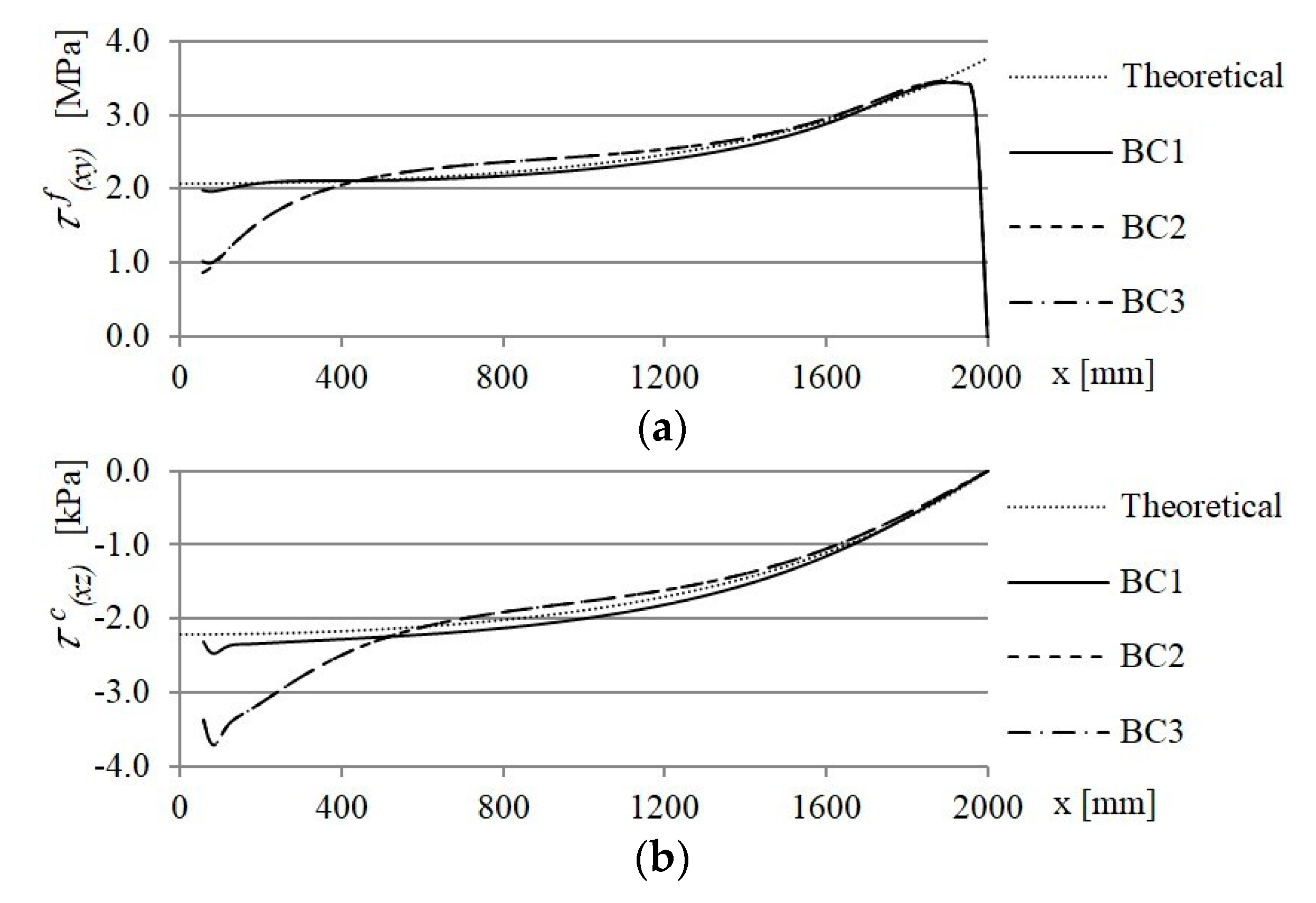
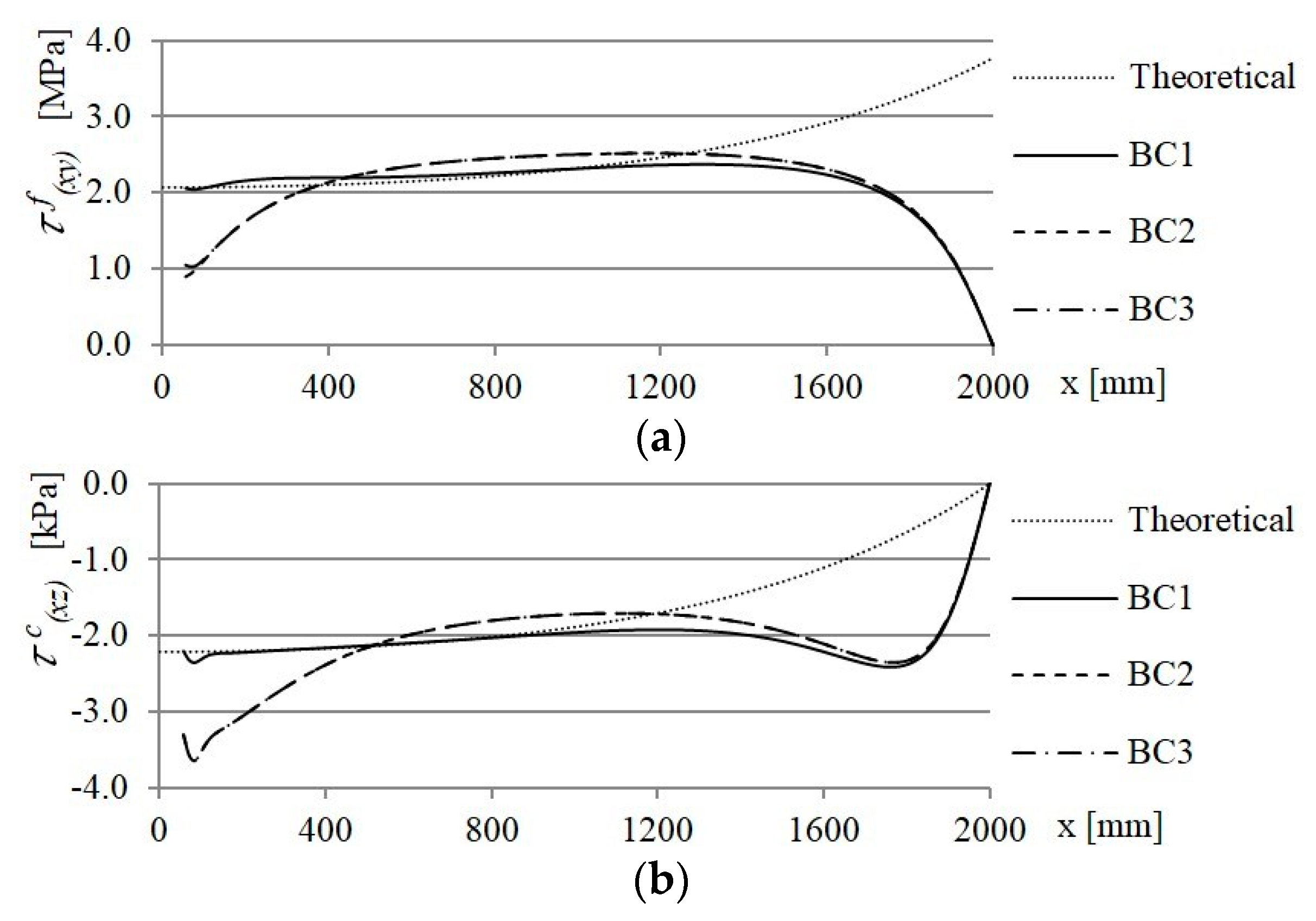
In the case of the distribution of shear stresses in the bottom facing and in the core of sandwich panel, the influence of changes in boundary conditions was noticeable primarily in close proximity to the supports. This is presented below on the example of the shear stress distribution in the longitudinal cross-section y = 250 mm.
For various HFP and VFP models (
Figure 4 and
Figure 5, respectively), at the supports, large differences in shear stress values can be observed, both in facings and in the core (in the middle of the core height
z = 0 mm). The results obtained from models BC2 and BC3 are practically identical, and the results of the BC1 model are close to the theoretical ones. Unblocking the possibility of displacements along the
y-direction of the upper supporting plates have crucial significance. In BC2 and BC3 models on the supports, the core strains are greater than in the BC1 model. Thus, one can observe an increase in the value of shear stresses in the core (almost 50%) and a decrease in the value of shear stresses in the facing (about 50%). As the distance from the support increases, this effect decreases and at a distance of about 400 mm from the supports, the shear stresses in the models BC2 and BC3 are very similar to those obtained in the BC1 model. The reduction of the stiffness of the support from the BC2 to BC3 models is not relevant for the shear stresses in the core and in the facing.
Differences between the theoretical and numerical results also occur in the middle of the span of the plate, i.e., in the place where the loading is applied. In the case of horizontal loading (HFP), they only concern shear stresses in the facings and occur in the narrow area near the center of the structure (x = 2000 mm). These differences are obvious because, theoretically, there should be a stress jump, which is impossible in practice; the more so as there is no concentrated load in the numerical model. Significant differences take place between theory and VFP models. The vertical pair of vertical forces, apart from the torsion of the sandwich element, also cause strong local bending, which leads to the increase of the shear stresses in the core and their decrease in the facing.
It should be clarified that all numerical results at the rigid supporting plate are characterized by certain disturbances. For various stresses, they have a different character; however, they are not important from the point of view of comparing the results with the theoretical solution. Therefore, these disturbances are not presented in the charts.
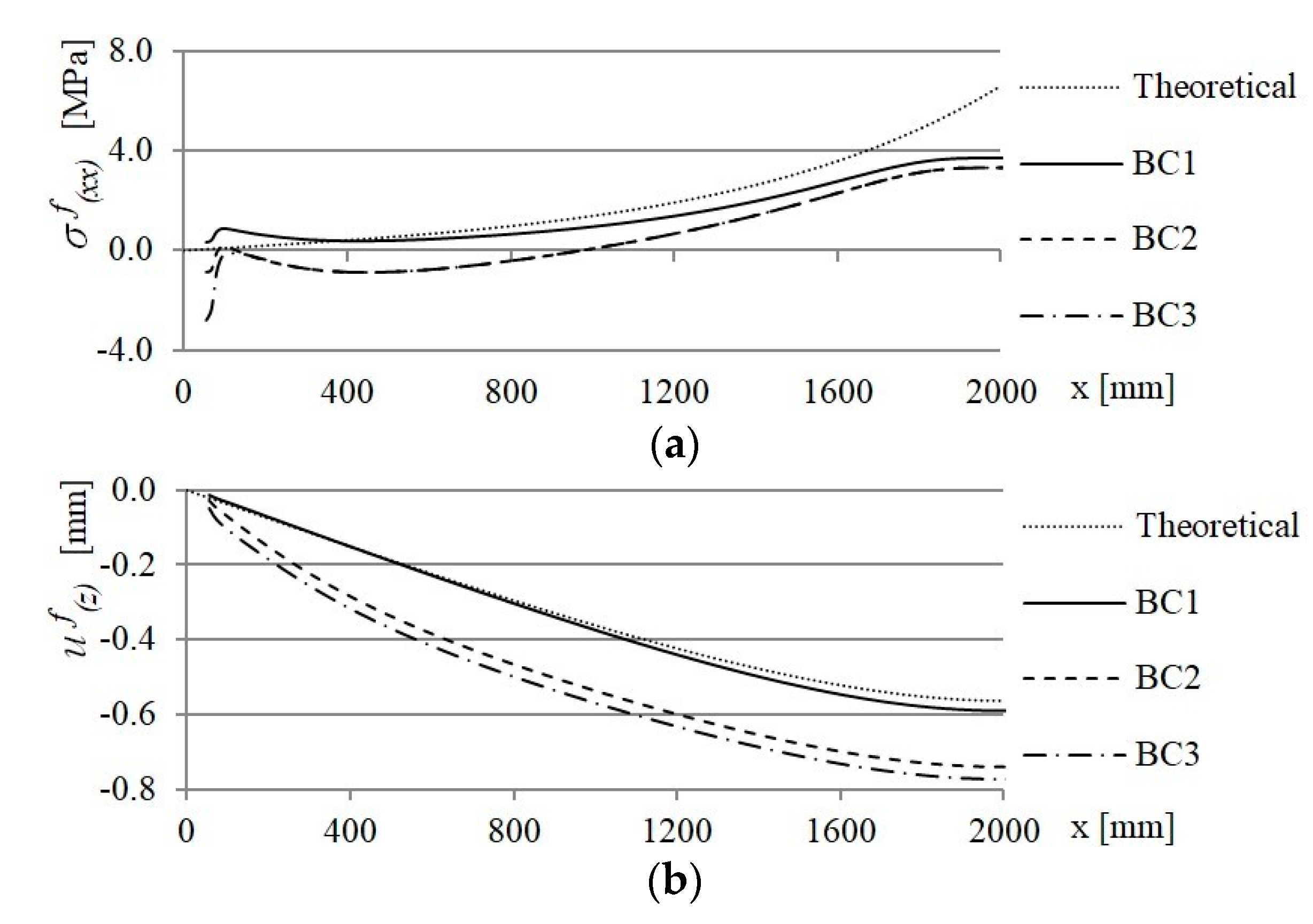
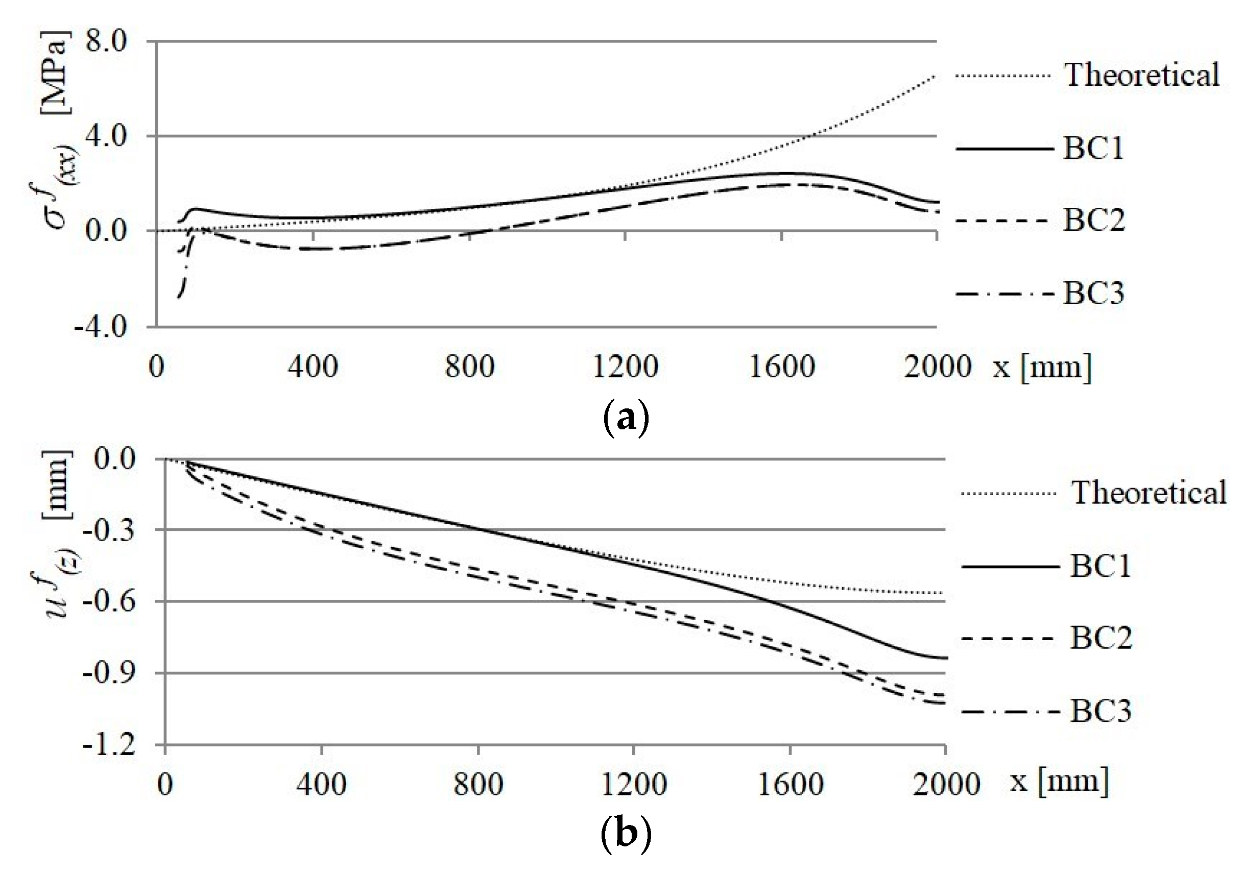
4.4. Vertical Displacements and Normal Stresses in the Facing
Figure 6 and
Figure 7 show the results obtained from the longitudinal cross-section
y = 250 mm of the HFP and VFP models, respectively. The results are compared to the theoretical solution presented in
Section 2.
The results presented in
Figure 6 and
Figure 7 show that the normal stresses from the BC2 and BC3 models reach apparently lower values than those in the BC1 model. Moreover, the BC2 and BC3 differ only at the support, which is obvious due to the completely different way of supporting and other support reactions (see
Table 1).
Interestingly, in the area of load application, normal stresses in numerical models are much smaller than in the theoretical model. This means that in HFP models, the load is distributed smoothly in the facings. The VFP models are similar, although in this case, there are additional effects of local core deformation and bending of the facings, which have an effect on normal stresses.
Comparing the vertical displacements, it can be concluded that the displacements of the BC1-HFP model are close to the theoretical beam model. Displacements of the BC1-VFP model are higher in the middle part of the plate because of the local deformations induced by applied load, as well as bending along the y-direction.
In the case of other numerical models, displacements are much larger than theoretical values. This is due to the lower stiffness of the supporting system, which allows a greater rotation of the plate on the support. This is of great practical importance as the sandwich panels are usually fastened to the support with connectors of some flexibility.
4.5. The Results on the Shell Thickness
Performing numerical analyzes, attention should be paid to the correct interpretation of the results. As described in
Section 3.1, the facings of sandwich panel were defined by the shell elements. In those elements, one of the dimensions (thickness) is much smaller than other two dimensions. It should be noted that the results (for example normal stresses) on the shell thickness do not have to be constant. It is worth clarifying here that the stresses shown in
Figure 6a and
Figure 7a (as well as
Figure 4a and
Figure 5a) are given for the extreme fibers of the cladding (z = 50 mm).
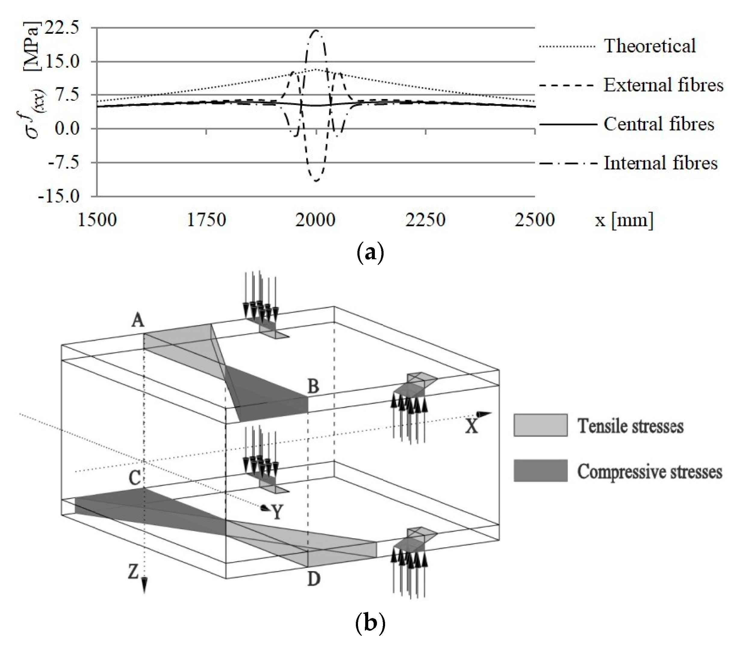
In the case of VFP models, in addition to the effect of the torsion, the facings are locally bent in the vicinity of the applied load.
Figure 8a presents values of normal stresses read out from external, central, and internal fibres of bottom facing in the longitudinal cross-section
y = 500 mm in the middle part of the BC1-VFP plate.
The graph clearly shows the local effect of bending of the facing on the results of normal stresses in the bottom facing. Local stress disturbances are much higher than the theoretical values, and they may even have the opposite sign. Nevertheless, the stress diagram is in each case symmetrical about the center of the element.
Figure 8b explains the phenomenon of variable stress values on the shell thickness. The global effect of torsion of the sandwich panel is the appearance of the antisymmetric (opposite directed) normal stresses at both edges of the facings. Compression occurs at points B and C, while there is tension at points A and D. The facings are locally bent due to the concentrated loading shown schematically in
Figure 8b using the arrows. As a result of the upward directed loads at points B and D, the upper fibres of the facings are tensioned and the lower ones are compressed. At points A and C, the load is directed downwards, which causes compression in the upper fibers and tension in the lower ones. The form of loading (perpendicular to facings) causes stresses of the same signs to appear in the internal fibres of the facings (lower fibres of the upper cladding, and upper fibres of the bottom one). Stresses of the opposite signs appear on the external fibres. This means that the extreme normal stresses are in the internal fibres of facings. This is confirmed by
Figure 8a. However, it is worth noting that the phenomenon is important for VFP models, only within the vicinity of the applied load.
5. Conclusions
The paper presented the issue of torsion of sandwich panels. Based on the example of a single-span plate, the influence of symmetrical boundary conditions (support and load) on the structural response was discussed. On the one hand, the conditions corresponding to the simplest theoretical model of a beam with a layered cross-section (with a shear deformable core) were sought. On the other hand, the sensitivity of a sandwich panel to changing these conditions is interesting, because it may be important for the safety of the structure in the actual conditions of its use.
The analyses carried out showed that the results most similar to a simple model of a sandwich beam were obtained in the case of the BC1-HFP numerical model, that is, assuming an opposite load acting in the plane of both facings, and support preventing displacement of both facings over the width of the plate, while leaving freedom of movement along its length. It is worth emphasizing that such conditions are purely theoretical, particularly in the method of supporting (plate fixing), which is always characterized by a certain flexibility. The conducted analyses show that the introduction of greater freedom of plate deformation on the support (BC2 and BC3 models are close to real conditions) leads to, among others, an increase the displacements and an increase (several times) in shear stresses in the core at the support.
The method of loading is also important. In the case of a concentrated load applied perpendicular to the facings, effects resulting from local deformations appear. They cause, among others, local disturbances in the distribution of normal stresses. Extreme stresses occur in the internal fibers of the facings, and they are much higher than the stresses obtained from a simple theoretical model.
The presented findings lead to a more general conclusion that in order to improve the safety of sandwich panels, the issue of torsion requires a further, deep analysis to develop better design methods.


