1. Introduction
With the continuous development of the integrated circuit industry and the increasing demand for low-power and high-performance devices in aerospace, nanodevices are widely used in space. However, these nanodevices are now becoming more and more sensitive to single-event effects (SEEs). An SEE can be caused by only one single energetic particle incidence and eventually leads to a spacecraft anomaly or damage, so it has attached much attention. Traditionally, SEEs of devices caused by a heavy ion (HI) and high-energy proton (HEP) are of greater concern. The main reason is that HIs have higher linear energy transfer (LET), and HEPs may undergo nuclear reactions with device materials to produce secondary particles with higher LET. As the operating voltage of semiconductor devices becomes lower, the critical charge required to cause a single-event upset (SEU) also becomes lower. Now it has been found that the low-energy proton (LEP, proton energy < 2 MeV) may cause an SEU in nanodevices through the direct ionization mechanism significantly. The on-orbit flux of LEP is several orders of magnitude higher than that of HEPs.
In 2007, Rodbell et al. first demonstrated in experiments that LEPs can cause an SEU in nanodevices through a direct ionization mechanism [
1]. The ensuing concern is whether the direct ionization mechanism of LEPs will substantially increase the total on-orbit SEU rate (OOSR). Based on this consideration, researchers have conducted a series of investigations on LEP-induced SEUs for different types of devices and in various research perspectives [
2,
3,
4,
5,
6,
7,
8,
9,
10,
11], and the contribution of LEPs to the total OOSR also became a hot research area [
2,
3,
6,
12,
13,
14].
Although the contribution of LEPs to the on-orbit error rate has been studied extensively, the major impact is still an open question. D. F. Heidel et al. first studied the contribution of LEPs to total OOSR, and the results show that OOSRs in Earth orbit due to LEPs for 65 nm SRAMs are much higher compared with HEPs [
2], while the study on 45 nm SRAMS by Ukhaseum et al. shows that the contribution ratio of the LEP-induced OOSR is only about 0.5% [
15]. After collating the research results of previous LEP-induced SEU studies, N. A. Dodds et al. conducted a more comprehensive study on the OOSR caused by LEPs [
6]. These research works mainly focused on the device itself and primarily studied the influence of device type and feature size on LEP-induced OOSR prediction. In contrast, the impact of orbital parameters on LEP-caused OOSR has not been studied. For the estimation of the OOSR, the settings of the device itself are only one factor, and the orbital parameters of the satellite are also critical.
This paper focuses on the impacts of orbital parameters on the OOSR of 65 nm commercial SRAM devices caused by a HI, HEP and LEP based on our previous experimental results. The orbital parameters include the orbital height, the inclination, the argument of periapsis (AOP), the right ascension of the ascending node (RAAN) and the satellite shielding (Al) thickness. In the process of estimating the OOSR, the calculation software used in this paper is SPACE RADIATION 7.0 [
16]. This paper is unique in several ways. Firstly, the previous software packages used to study LEP OOSR prediction were CRÈME, OMERE, etc., while SPACE RADIATION 7.0 is used in this paper. Moreover, in the process of modeling, the OOSR calculations were carried out using raw data import. Secondly, the previous research focused on the device itself and mainly studied the influence of device type and feature size on LEP OOSR prediction. However, the focus of this paper is mainly to study the impact of satellite orbit parameters on OOSR prediction. Thirdly, in the study of OOSR prediction caused by LEPs, this paper does not just select several typical satellite orbits as in the previous study but conducts research on the continuous changes of each orbital parameter. Finally, the parametric variables studied in this paper include AOP, RAAN and inclination, which were never considered in the previous literature of LEP OOSR prediction. The research results of this paper have great reference value for the application of nanodevices in aerospace, especially in the current commercial satellite field.
2. Simulation Setting Details
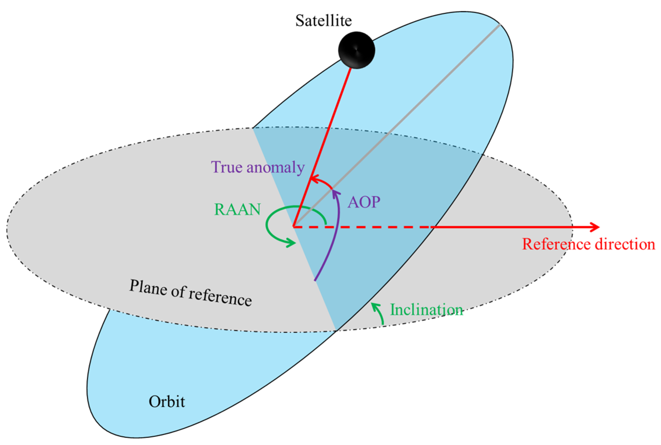
For satellites performing different missions, their orbits are also varying, which means that the OOSR of on-board spacecraft electronics (OBSEs) will also be different. There are many factors to be considered in the design of the satellite orbit, but ultimately, it is about the choice of six orbital parameters. The six satellite orbital parameters contain three directional parameters and three geometric shape parameters, which are: the RAAN, the inclination, the AOP, the eccentricity, the semi-major axis and the true anomaly. Only five of these six orbital parameters may have an impact on the OOSR of OBSEs. The true anomaly has no impact on the estimation of the OOSR since it is only used to describe the initial position of the satellite on its orbit.
In addition, the eccentricity and the semi-major axis can be calculated by the following formula:
where
is the semi-major axis,
is the eccentricity,
is the apogee and
is the perigee. The radius of Earth is generally not negligible relative to the height of the perigee and apogee, so the height of the perigee and the apogee are known for the satellite orbital design. Therefore, we replace the two parameters of the semi-major axis and the eccentricity by the perigee and the apogee.
Figure 1 shows the parameters describing satellite orbits. In addition, to more intuitively simulate the impact of the satellite orbital height on the OOSR, we set the perigee and the apogee to the same when considering the impact of orbital height on the OOSR, and the orbital height was set to
when we studied the other orbital parameters affecting the OOSR. The detailed orbital parameters settings used in the simulation are shown in
Table 1.
SPACE RADIATION is a comprehensive software tool for calculating the space radiation environment and radiation effect of spacecraft. It was developed by Space Radiation Associates in the 1990s. After several revisions, the current latest version is SPACE RADIATION 7.0. In the calculation of the on-orbit error rate estimation of devices using SPACE RADIATION software, the main processes are as follows:
- (1)
Set the satellite orbital parameters, including perigee, apogee and inclination. When setting the orbital parameters, the parameters that affect the orbit are all discussed in this paper. The existence of some other parameters has no impact on the orbit description, the radiation environment of the satellite and the OOSR of the device.
- (2)
Select the geomagnetic shielding conditions. The orbit-integrated geomagnetic selected in this work is “average”, and the absorption of cosmic radiation by Earth’s atmosphere is considered. In addition, the choice of particle arrival direction is omnidirectional, and the influence of a magnetic storm is not considered in this paper.
- (3)
Calculate the radiation environment, including heavy ions, solar protons and trapped protons. The simulation models selected when calculating the space radiation environment are the CHIME model [
17], SOLPRO model [
18] and AP-8 model [
19] in this work
- (4)
Set spacecraft shielding conditions and generate the linear energy transfer (LET) spectra. The selected shielding material is aluminum, and the calculation of the LET spectrum is derived from the conversion of the energy spectrum.
- (5)
Calculate the on-orbit error rate in combination with experimental data or the Weibull fit function. The OOSR of the device caused by protons is calculated by directly importing experimental data, which is also the advantage of the SPACE RADIATION software, while the OOSR caused by heavy ions is calculated by the Weibull fitting curve.
3. Results and Discussion
The data used in the calculation are derived from a CYPRESS 65 nm CMOS SRAM device experimental SEU test. We conducted an SEU test irradiated by protons for this device. The experimental SEU cross-section induced by LEPs and HEPs was published in [
8], and the SEU data of the HI are derived from [
20].
3.1. Orbital Height
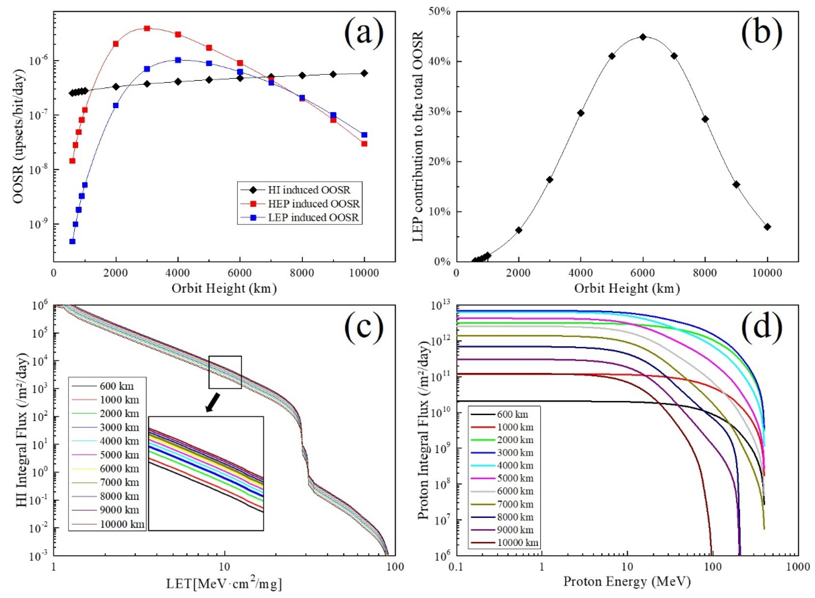
No matter what the specific tasks performed by the satellite are, the orbital height is undoubted to be considered. The change in satellite orbital height also means that the space radiation environment the OBSEs faced changes. In calculating the OOSR as a function of orbital height, the orbital height ranges from 600 to 10,000 km. The calculated results of the OOSR induced by an HI, LEP and HEP as a function of orbital height are shown in
Figure 2a. It can be seen from the figure that with the continuous increase in the orbital height, the trend of the OOSR caused by the LEP and HEP is the same, where both increase first and then decrease. The maximum value of the OOSR caused by the LEP and HEP occurs near the orbital height of 3000 km. Further, with the orbital height increase, the HEP-induced OOSR is higher than that of the LEP at the beginning. When the track height increases to about 8000 km, the OOSR caused by the LEP will be higher than the HEP. Moreover, the changing trend of the OOSR caused by the HI is not the same as that of protons when the orbital height increases. There is no tendency to increase first and then decrease. Instead, as the orbital height increases, the OOSR caused by the HI slowly increases. The OOSR caused by the HI is higher than of protons when the orbital height is lower than 1000 km or higher than 7000 km. The variation in the OOSR caused by the LEP, HEP and HI with orbital height is closely related to the change in the radiation environment.
Figure 2c,d show the HI and proton on-orbit integral flux under different orbital heights. It can be seen from the figure that the integral flux of the HI increases with the increase in the orbital height, while the integral flux of protons increases first and then decreases with the increase in the orbital height. This is consistent with the trend of OOSR values caused by the LEP, HEP and HI.
Figure 2b shows the trend of the LEP contribution to the total OOSR as a function of orbital height. From the figure, we can see that the LEP contribution to the total OOSR increases first and then decreases as the orbital height increases. When the orbital height is 6000 km, the LEP contribution to the total OOSR reaches the maximum value, which is 44.9%. It can be seen from the above data analysis that the orbital height has a significant impact on the LEP contribution to the total OOSR. As the orbital height increases from 600 to 10,000 km, the LEP contribution rate is between 0.2% and 44.9%. It is unreliable to talk about the LEP′s contribution to the total OOSR aside from the influence of orbital height.
3.2. Inclination
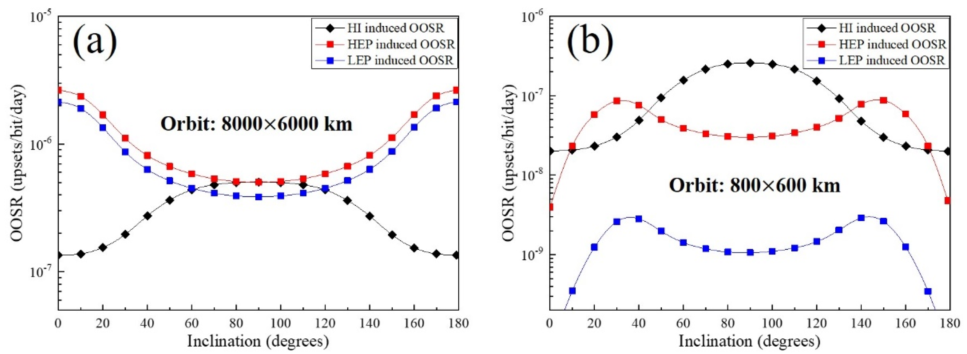
Figure 3 presents an overview of the impact of inclination on the OOSR under two different orbital heights. As can be seen from the figure, as the inclination changes from 0 degrees to 180 degrees, the OOSR caused by the HI trend is consistent regardless of the orbital height, but the OOSR caused by protons trend is different. The OOSR caused by the HI increases first and then decreases as the inclination angle increases from 0 degrees to 180 degrees. When the orbital height is
, the proton-induced OOSR changes with the inclination are exactly opposite to the HI, which decreases first, reaches the lowest value at 90 degrees and then increases. When the orbital height is
, the proton-induced OOSR exhibits a symmetrical bimodal curve, which reaches its maximum when the inclination angle is 30 degrees and 150 degrees.
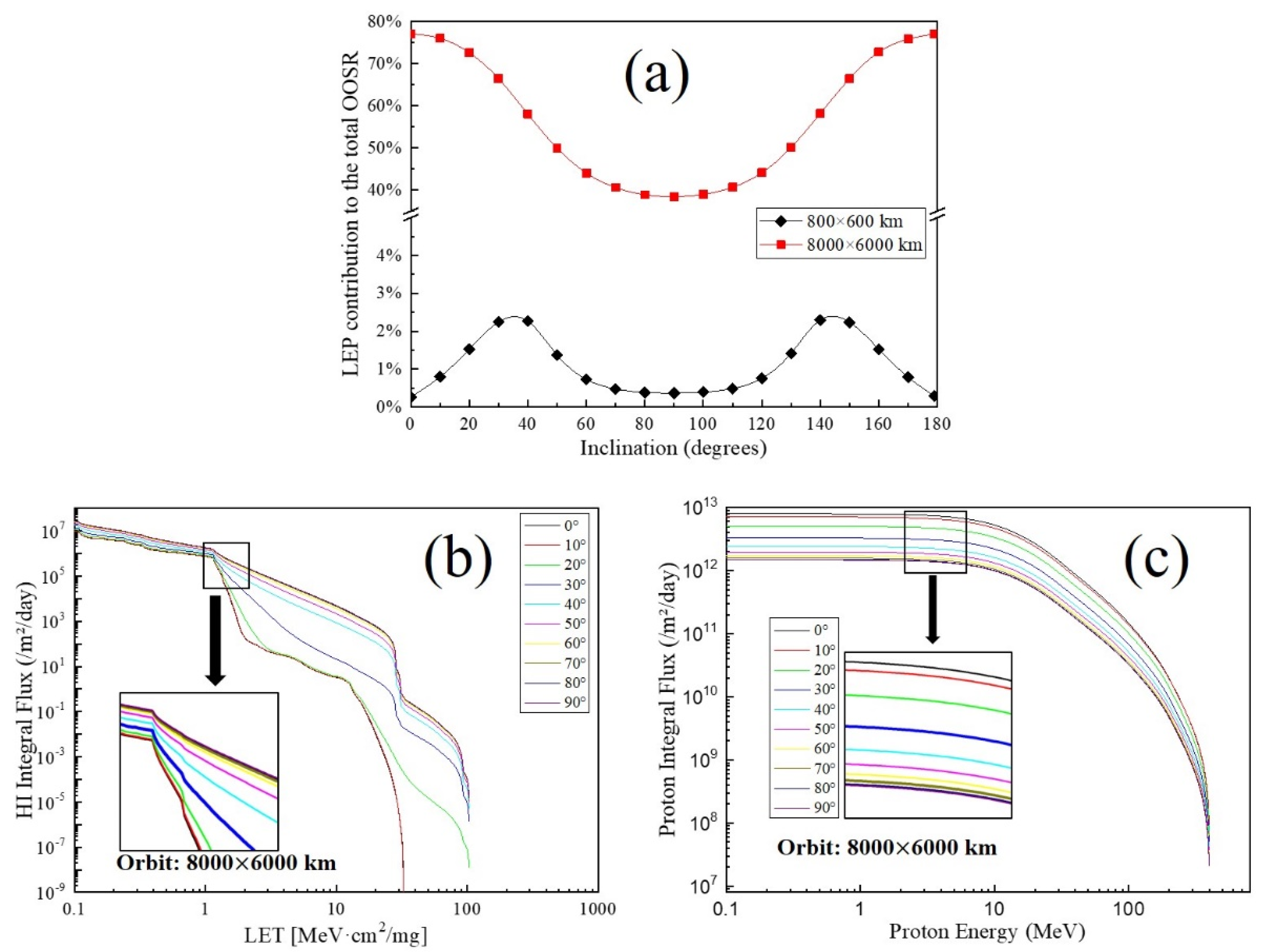
After obtaining the OOSR under different inclination parameters, we calculated the contribution of the LEP to the total OOSR, as shown in
Figure 4a. It can be seen from the figure that the changing trend of the LEP contribution to the total OOSR with the inclination is consistent with the OOSR caused by the proton. When the orbital height is 8000 km × 6000 km, as the inclination increases from 0 degrees to 180 degrees, the LEP contribution ranges from 38.4% to 77.1%. Meanwhile, when the orbital height is 800 km × 600 km, the LEP contribution just ranges from 0.3% to 2.3%. Therefore, it can be concluded that the change in inclination has a more significant impact on the LEP contribution rate, and this effect is symmetrical. The conclusion of symmetry can also be seen from the influence of inclination on the HI and proton integral flux, as shown in
Figure 4b,c. For the on-orbit proton integral flux, as the inclination increases from 0 degrees to 90 degrees, the proton flux continuously decreases. However, when the inclination angle continues to increase from 90 degrees to 180 degrees, the proton flux increases precisely in an opposite manner. This also means that the proton integral flux curve is the same for inclination angles of 20 degrees and 160 degrees. From the above analysis, it can be seen that the variation in the inclination also has a non-negligible effect on the contribution of the LEP when the orbital height is certain.
3.3. RAAN and AOP
RAAN and AOP are also important parameters used to describe satellite orbits. The calculation result of the impact of RAAN and AOP parameter changes on the OOSR is shown in
Figure 5. As can be seen from
Figure 5a,b, the HI- and proton-induced OOSRs remain unchanged regardless of the RAAN, which ultimately leads to no impact of the RAAN parameter variation on the LEP contribution to the total OOSR. When the orbital height is 8000 km × 6000 km, the OOSR contribution due to the LEP is maintained at about 38.4% regardless of the RAAN variation. In addition,
Figure 5c,d show the variation in the HI, proton-induced OOSR and LEP contribution to the total OOSR with AOP parameters. From
Figure 5c, it can be seen that the AOP parameter has no impact on the OOSR caused by the HI, but not for the OOSR caused by protons, especially for the OOSR caused by the HEP. With different AOP parameters, the contribution of the LEP-induced OOSR varies in the range of 38.4% to 41.5%. Therefore, it can be concluded that the RAAN and the AOP have little impact on the LEP contribution to the total OOSR compared with other parameters and are sometimes negligible.
3.4. Shielding
Finally, we studied the impact of satellite shielding thickness on the OOSR. The calculated results are shown in
Figure 6. It can be seen from
Figure 6a that the shielding thickness has a significant impact on the OOSR caused both by protons and the HI. Whether for protons or the HI, the OOSR is reduced as the thickness of the shielding increases. However, the shielding thickness has a smaller impact on the OOSR caused by the HI and HEP. The OOSR caused by the LEP is reduced by an order of magnitude, while the thickness of Al increases from 100 to 200 mils. The LEP-induced OOSR is
when the shielding thickness is 100 mils and drops to
when the shield thickness is increased to 200 mils.
Figure 6b shows the LEP contribution to the total OOSR under different shielding thicknesses. It can be seen from the figure that the contribution of the LEP to the total OOSR is 37.7% when the shield thickness is 100 mils and decreases sharply as the shield thickness increases. By the time the shield thickness is increased to 500 mils, the contribution of the LEP is already less than 1.0%. Then, as the shield thickness continues to increase, the contribution of the LEP decreases more and more slowly. The reason for the trend in the LEP contribution to the total OOSR can be explained by the impact of the shielding thickness on the HI and proton integral flux, as shown in
Figure 6c,d. As can be seen from the figure, the HI integral flux decreases slowly and linearly with increasing shielding thickness. In addition, it is obvious that the increase in shielding thickness for the proton integral flux mainly affects the LEP, and the impact of integral flux is not as pronounced for the HEP. From the above analysis, it can be seen that the shielding thickness has a significant impact on the on-orbit integral flux of the LEP and the resulting contribution to the total OOSR. Increasing the shielding thickness is an effective means to reduce the OOSR caused by the LEP and the LEP contribution to the total OOSR.
4. Conclusions
Based on the experimental SEU test data of the CYPRESS 65 nm CMOS SRAM, this paper conducts a modeling study on the influence of orbital parameters on accurately estimating the OOSR of OBSEs induced by an HI, HEP and LEP. Specific OOSRs due to the HI, HEP and LEP in different orbital parameters were calculated, and the LEP contribution to the total OOSR was also obtained. Finally, the results were discussed and analyzed by the HI and proton integral flux under specific orbital parameters. The results indicate that these five parameters described in the paper will affect the accurate estimation of the OOSR of the device. Among them, the orbital height, inclination and the thickness of the shielding have a more significant impact on accurately estimating the OOSR compared with the RAAN and the AOP, and it is the same for the contribution of the LEP to the total OOSR. Of course, due to experimental data limitations, this paper only discusses and analyzes this 65 nm CMOS SRAM device. For other nanodevices, there may be some differences in the details of the impact of the specific orbital parameters on the OOSR, and this is also the part we need to strengthen in the future.
Author Contributions
Conceptualization, B.Y.; methodology, B.Y. and L.-H.M.; software, B.Y.; validation, T.L.; formal analysis, B.Y. and L.-H.M.; investigation, B.Y. and L.-H.M.; writing—original draft preparation, B.Y.; writing—review and editing, B.Y.; supervision, J.L. and Y.-M.S.; project administration, J.L. and B.Y.; funding acquisition, J.L. and B.Y. All authors have read and agreed to the published version of the manuscript.
Funding
This research was funded by National Natural Science Foundation of China, grant number 11690041 and 11675233. And also funded by Science and Technology on Analog Integrated Circuit Laboratory, grant number JCKY2019210C054.
Conflicts of Interest
The authors declare no conflict of interest.
References
- Rodbell, K.P.; Heidel, D.F.; Tang, H.H.K.; Gordon, M.S.; Oldiges, P.; Murray, C.E. Low-energy proton-induced single-event-upsets in 65 nm node, silicon-on-insulator, latches and memory cells. IEEE Trans. Nucl. Sci. 2007, 54, 2474–2479. [Google Scholar] [CrossRef]
- Heidel, D.F.; Marshall, P.W.; LaBel, K.A.; Schwank, J.R.; Rodbell, K.P.; Hakey, M.C.; Berg, M.D.; Dodd, P.E.; Friendlich, M.R.; Phan, A.D.; et al. Low energy proton single-event-upset test results on 65 nm SOI SRAM. IEEE Trans. Nucl. Sci. 2008, 55, 3394–3400. [Google Scholar] [CrossRef]
- Sierawski, B.D.; Pellish, J.A.; Reed, R.A.; Schrimpf, R.D.; Warren, K.M.; Weller, R.A.; Mendenhall, M.H.; Black, J.D.; Tipton, A.D.; Xapsos, M.A. Impact of low-energy proton induced upsets on test methods and rate predictions. IEEE Trans. Nucl. Sci. 2009, 56, 3085–3092. [Google Scholar] [CrossRef]
- Cannon, E.H.; Cabanas-Holmen, M.; Wert, J.; Amort, T.; Brees, R.; Koehn, J.; Meaker, B.; Normand, E. Heavy ion, high-energy, and low-energy proton SEE sensitivity of 90-nm RHBD SRAMs. IEEE Trans. Nucl. Sci. 2010, 57, 3493–3499. [Google Scholar] [CrossRef]
- Weulersse, C.; Miller, F.; Alexandrescu, D.; Schaefer, E.; Crepel, O.; Gaillard, R. Test methodology of a new upset mechanism induced by protons in deep sub-micron devices. Microelectron. Reliab. 2012, 52, 2482–2486. [Google Scholar] [CrossRef]
- Dodds, N.A.; Martinez, M.J.; Dodd, P.E.; Shaneyfelt, M.R.; Sexton, F.W.; Black, J.D.; Lee, D.S.; Swanson, S.E.; Bhuva, B.L.; Warren, K.M.; et al. The contribution of low-energy protons to the total on-orbit SEU rate. IEEE Trans. Nucl. Sci. 2015, 62, 2440–2451. [Google Scholar] [CrossRef]
- Yin-Hong, L.; Feng-Qi, Z.; Yan-Ping, W.; Yuan-Ming, W.; Xiao-Qiang, G.; Hong-Xia, G. Single event upsets sensitivity of low energy proton in nanometer static random access memory. Acta Phys. Sin. 2016, 65, 068501. [Google Scholar]
- Ye, B.; Liu, J.; Wang, T.-S.; Liu, T.-Q.; Luo, J.; Wang, B.; Yin, Y.-N.; Ji, Q.-G.; Hu, P.-P.; Sun, Y.-M. Impact of energy straggle on proton-induced single event upset test in a 65-nm SRAM cell. Chin. Phys. B 2017, 26, 088501. [Google Scholar] [CrossRef]
- Wang, Z.; Chen, W.; Yao, Z.; Zhang, F.; Luo, Y.; Tang, X.; Guo, X.; Ding, L.; Peng, C. Proton-induced single-event effects on 28 nm Kintex-7 FPGA. Microelectron. Reliab. 2020, 107, 113594. [Google Scholar] [CrossRef]
- Rodbell, K.P. Low energy protons—Where and why “rare events” matter. IEEE Trans. Nucl. Sci. 2020, 7, 1204–1215. [Google Scholar] [CrossRef]
- Peng, C.; Chen, W.; Luo, Y.; Zhang, F.; Tang, X.; Wang, Z.; Ding, L.; Guo, X. Low-energy proton-induced single event effect in NAND flash memories. Nucl. Instrum. Methods Phys. Res. Sect. A 2020, 969, 164064. [Google Scholar] [CrossRef]
- Hubert, G.; Duzellier, S.; Bezerra, F.; Ecoffet, R. MUSCA SEP3 contributions to investigate the direct ionization proton upset in 65nm technology for space, atmospheric and ground applications. In Proceedings of the 2009 European Conference on Radiation and Its Effects on Components and Systems (RADECS), Brugge, Belgium, 14–18 September 2009; pp. 179–186. [Google Scholar]
- Dodds, N.A.; Schwank, J.R.; Shaneyfelt, M.R.; Dodd, P.E.; Doyle, B.L.; Trinczek, M.; Blackmore, E.W.; Rodbell, K.P.; Gordon, M.S.; Reed, R.A.; et al. hardness assurance for proton direct ionization-induced sees using a high-energy proton beam. IEEE Trans. Nucl. Sci. 2014, 61, 2904–2914. [Google Scholar] [CrossRef]
- Haddad, N.F.; Kelly, A.T.; Lawrence, R.K.; Li, B.; Rodgers, J.C.; Ross, J.F.; Warren, K.M.; Weller, R.A.; Mendenhall, M.H.; Reed, R.A. Incremental enhancement of SEU hardened 90 nm CMOS memory cell. IEEE Trans. Nucl. Sci. 2011, 58, 6. [Google Scholar] [CrossRef]
- Sukhaseum, N.; Samaras, A.; Gouyet, L.; Pourrouquet, P.; Chatry, N.; Bezerra, F.; Ecoffet, R.; Lorfevre, E. A Calculation Method for Proton Direct Ionization Induced SEU Rate from Experimental Data: Application to a Commercial 45 nm FPGA. In Proceedings of the Nuclear and Space Radiation Effects Conference (NSREC), Paris, France, 14–18 July 2014. [Google Scholar]
- Space Radiation Associates. Available online: http://www.spacerad.com/index.html (accessed on 14 November 2019).
- Chenette, D.L.; Chen, J.; Clayton, E.; Guzik, T.G.; Wefel, J.P.; Garcia-Munoz, M.; Lopate, C.; Pyle, K.R.; Ray, K.P.; Mullen, E.G.; et al. The CRRES/SPACERAD heavy ion model of the environment (CHIME) for cosmic ray and solar particle effects on electronic and biological systems in space. IEEE Trans. Nucl. Sci. 1994, 41, 2332–2339. [Google Scholar] [CrossRef]
- Stassinopoulos, E.G. SOLPRO: A Computer Code to Calculate Probabilistic Energetic Solar Proton Fluences; NASA NSSDC 75-11; National Aeronautics and Space Administration: Washington, DC, USA, 1975. [Google Scholar]
- Jordan, C.E. NASA Radiation Belt Models AP-8 and AE-8; Radex Inc.: Bedford, MA, USA, 1989. [Google Scholar]
- Nm, A. SEE Final Report for Cypress Semiconductor CYRS1543AV18, 72-Mbit QDR SRAMs. Available online: http://www.cypress.com/file/123726/download (accessed on 8 December 2020).
| Publisher’s Note: MDPI stays neutral with regard to jurisdictional claims in published maps and institutional affiliations. |
© 2020 by the authors. Licensee MDPI, Basel, Switzerland. This article is an open access article distributed under the terms and conditions of the Creative Commons Attribution (CC BY) license (http://creativecommons.org/licenses/by/4.0/).


