Article

Cornering Algorithm for a Crawler In-Pipe Inspection Robot

1
School of Mechanical, Electrical and Information Engineering, Shandong University (Weihai), Weihai 264209, China
2
Department of Electrical & Electronics Engineering, Chungnam State University, Cheongyang 33303, Korea
*
Author to whom correspondence should be addressed.
Symmetry 2020, 12(12), 2016; https://doi.org/10.3390/sym12122016
Submission received: 11 November 2020 / Revised: 1 December 2020 / Accepted: 4 December 2020 / Published: 6 December 2020

Abstract

:
Based on the large-scale wall-pressing three-legged crawler pipeline inspection robot, our team proposed a cornering algorithm based on space constraints, that aims to better control the smooth operation of the pipeline robot in the pipeline. This algorithm is aimed at large robots that use an electric telescopic rod structure to replace the elastic structure on traditional small robots. The electric telescopic rod structure meets the large-scale weight change of the robot and provides sufficient supporting force. However, this structure also makes it difficult for the robot to automatically adapt to the change of pipe diameter and increases the difficulty of the robot’s control. In order to solve this problem and more accurately control the operation of the robot during cornering, this paper analyzes the space constraints of the robot when turning, the optimization analysis of the telescopic rod expansion and the ratio of the speed of each crawler, obtaining a stable turning algorithm for pipeline robots. The algorithm guarantees that the robot can provide sufficient support in the bend pipeline, and that it has good stability and mobility.

1. Introduction

1.1. Classification of the In-Pipe Robot

In order to meet the requirements of accomplishing pipeline overhaul detections and reducing the risk of manual operations, pipeline robots rose in response to the proper time and conditions. In-pipe detection robots are more popular than external ones [1]. The pipe inspection robot can be classified in the following categories: wheeled robots, inchworm robots and crawler robots. Among them, wheeled pipe robots are the most commercially adopted and most commonly used. Wheeled pipe robots have the characteristics of effective flexibility and low power consumption [2], but lack stability, for example: the six-wheel drive in-tube robot that has difficulty moving through bent pipe smoothly [3]. The peristaltic pipeline inspection robot [4,5] has a simple structure and high motor utilization rate, but its complex mechanical structure results in space constraints, making it difficult to pass through a damaged or concave straight pipe or bent pipe. In order to improve the robot’s stability within pipes, we assume that the robot also exhibits symmetry, in which case the robot motion analysis in the pipe can be simplified considering the symmetrical structure of the pipe. Compared with wheeled robots, crawler robots have greater traction due to a larger contact area with the pipe walls. However, due to the structural requirements of the crawler robot’s own crawler, the constraints in the pipe are extremely complicated, such as with the robots in [6,7] that have difficulties in analysis, making them uncontrollable. Dertien, E.C [8], Wu, Y [9] and Yamamoto, T [10] also proposed similar types of robots in their paper. However, under the current trend of large-scale pipelines, large-scale crawler-type pipeline inspection robots with a variety of kinds of sensors are gradually becoming mainstream.

1.2. Problems with the In-Pipe Robot in Control

A lot of research on pipeline robots focuses on the autonomous operation of robots, which needs to be based on a large amount of sensor information [1]. In general, the contact position between the robot and the inner wall of the pipe is not in the same plane, which indicates that the motion analysis and control analysis of the robot inside the pipe is more difficult than the analysis outside the pipe. When running in the pipe, compared with other situations, the movement of the robot in straight pipe is simple. Almost all kinds of pipeline robots can pass smoothly in an absolute straight pipe. The robot only needs to control the running speed of each foot to be the same [1].
For wall-pressed crawler robots, the wall-pressed structure enables the crawler robot’s crawler to have a high degree of fitting with the inner wall of the pipe. This structure has great traction, strong stability and high efficiency [11]. Therefore, caterpillar detection robot has become the mainstream of current detection.
Although there are many studies at present for curved pipes and deformed pipes there is no perfect solution, due to the constraints of the arc-shaped pipe space and the limitations of the robot’s own parameters; the analysis of the wheels or crawlers in the pipe is in three-dimensional space [12], and the posture of the robot’s movement in the bend and the degree of contact with the pipe are difficult to analyze in detail. In addition, most studies only focus on robots with elastic structures that change automatically according to the pipe diameter. However, most large pipeline robots now need to carry multiple modules for work, so, the load bearing requirements are large and the elastic structure cannot meet the movement requirements of robots. At the same time, most analyses only focus on the duration after the robot has entered the bend, and do not involve the transition stage from straight pipe to bend [6].
However, with the popularization of large pipes, the traditional small robots of this kind are no longer suitable, and large robots have been developed; but the traditional elastic structure cannot support the stable operation of large pipeline robot inside the pipe. Therefore, we use an electric telescopic rod instead of an elastic structure to ensure the stability of robot operation. Due to the narrow internal space of the pipeline, especially for bends and damaged pipelines, the space of the large robot itself is limited and its track cannot automatically adapt to pipe diameter change. A key problem becomes the method of analyzing the robot’s own posture and realizing its stable movement inside the pipeline.
The robot will encounter the following problems when it turns in the curved tube. First of all, in order to simplify the analysis, the robots are often approximated as rigid body structures [1], whose structures cannot be changed with the bending of pipes. When passing through the curved part, the original contact area changes, and even the crawler foot loses contact with the pipe wall. In most cases, only one to two or a few points per crawler foot contact the pipe [6]. The position and speed of these points are related to the center of the robot and the relative position of the pipe. Therefore, the method of analyzing the position of the pipeline robot in the pipe becomes a big problem for the motion control of the pipeline robot. In order to accurately analyze the contact between the crawler foot in the pipeline and the inner wall of the pipeline, most studies adopt the closed kinematics model to carry out the kinematics analysis of the robot in the pipeline, so as to propose the robot motion planning algorithm in the pipeline. For example, the robots in papers of T. Oya [13], Atsushi Kakogawa [14], Harish, P [15] and Sum Zhang, Y [16] adopt this method for analysis. Differential drive method is often used for robot movement in the curve, and differential drive method is adopted for the pressure-wall robot in [12].
Kakogawa et al. [14] has improved the robot structure. Previously, the traditional elastic structure was located between the crawler and the main body. Now, the traditional elastic structure is transferred to the main body. This allows the front and rear parts of the single crawler foot of the robot to change correspondingly according to different environments, so as to better adapt to the curve. They also propose a method of controlling the robot by modulating speeds of driving wheels that is applicable without sophisticated sensory information.
However, the algorithm is complex and according to their experiences on work in [14], the mechanism of the in-pipe robot should be adaptable to the characteristic condition of the pipelines, and it is the preliminary requirement for successful movement. It means that the use of a general-purpose robot may not be possible in in-pipe applications.
In order to avoid the lack of binding force at the T-shaped pipeline entrance, the robot proposed by Kwon, Y.S. et al. [5] adopts the method of combining two crawler robots, that is, a spring structure is added between the two sections. In the process of entering and leaving the elbow part, the spring performs push and pull operations on the front and rear modules respectively. Through the above operations, the efficiency of robot passing through the elbow and T-shaped pipe is effectively improved. But at the same time, it doubles the robot’s energy consumption. In addition, it does not have complicated kinematics calculations, and it compensates for the shortcomings in the operation of a single module by co-designing the differential drive method of the same two modules. However, the algorithm does not construct complete constraints. Therefore, in the case of large fluctuations in the load of the robot itself, the previous stability of the algorithm cannot be guaranteed, resulting in the separation of the crawler foot and the pipe in the cornering progress.
As the most widely used detection robot in pipelines, the crawler wall-pressing detection robot of this kind of small traditional robot uses elastic structure to connect the crawler foot to the main body, which can pass through the track bend automatically and does not need complex control algorithm.
In the process of using the pipe, the different positions of the robot and the degree of the pipe diameter change, so, the pipe robot’s automatic adaption to the change of pipe diameter is a problem that cannot be ignored. Currently, there are two methods to realize the automatic pipe diameter adaptation of the robot. The difference lies in whether the connection part of the crawler and the main bracket is an active module or a passive module. These two methods require the symmetry of the robot to ensure that the center of the robot is in the center of the pipeline. Active modules, that is, controllable expansion actuators are used to expand and contract. Such methods usually need to be matched with appropriate pressure sensors to determine the radial pressure from the pipe wall received by the crawler foot. For example, the robot in [3] uses a scissor chain structure driven by spiral components to automatically adapt the pipe diameter. The advantage of this method is that it can actively control the pressure of the robot’s crawler foot and pipe diameter, for example, providing enough friction for the robot’s climbing process in a vertical pipe. For pipe robots, however, the installation of telescopic actuators requires more space and more complex control methods, so this method is generally not used by small pipe robots. The other way is to make the crawler foot adjust automatically with the appropriate elastic parts. At present, the mass-spring-damper model is mostly used. For example, in the robot presented in Li, T. et al. [4], the robot with its rollers are spring-pressed on the inner wall of the pipe and the appropriate spring is selected from the inside of the elastic arm to provide enough force for the robot. Kwon et al. [5] added springs to the three spindles in the center of the robot, so as to adapt to the change of the inner diameter of the pipe. However, when the elastic part causes passive contraction of the crawler foot, the irregular surface will cause the overall deviation of the robot. In addition, these robots are usually unable to adapt to various diameter changes, and this structure cannot adjust the normal force [17]. The machines in [13,14,15,16] adopt flexible springs for adjustment, which are also used by most robots. In order to eliminate the negative effects of external interference and parameter uncertainty, the robot must be equipped with an active control system [18].

The Robot of this Paper

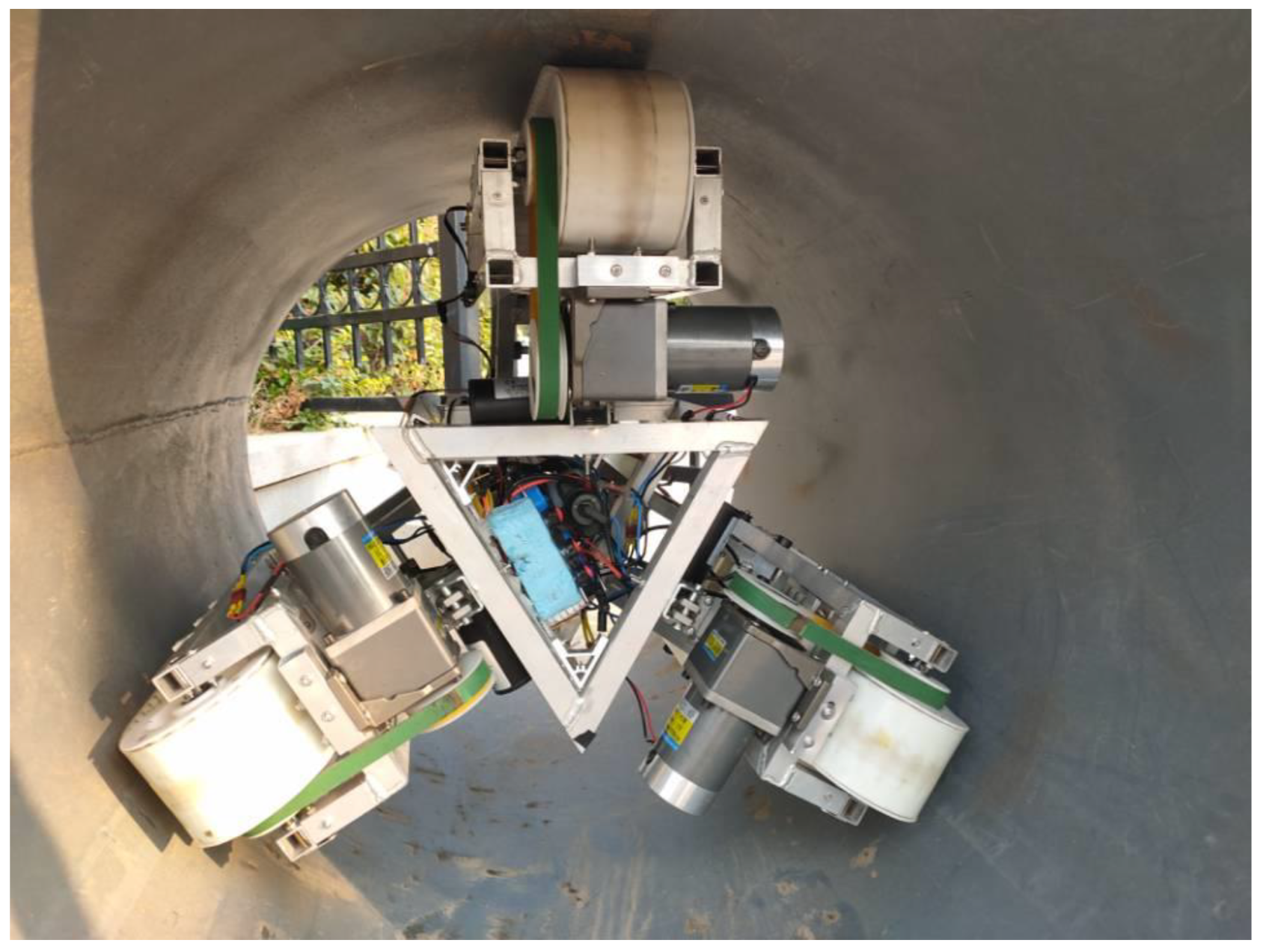
This paper is based on a crawler pipeline robot, which is composed of three crawler modules arranged symmetrically in the circumferential direction at an interval of 120 degrees. Each foot is perpendicular to the inner wall of the pipeline and is equipped with a driving motor, so that the three-foot speeds are independent of each other. As shown in Figure 1, the three-legged symmetric structure not only improves the traction force, but also ensures that the analysis method is exactly the same as before each rotation of the robot in the tube when it rotates at 120 degrees, thus simplifying the difficulty of algorithm implementation. In addition, the structure improves the robot’s ability to move in a complex environment and avoids the possibility of rolling over when the biped robot encounters a large irregular object. The robot is shown in Figure 2.
Each module is connected to the central base unit by an electric telescopic rod. The contractible structure can be actively extended to the inner wall of the pipe by telescopic devices. The robot can move independently inside the pipe. The robot’s three-track full expansion range is 813–139 mm, which can adapt to the pipe diameter range of 813–1219 mm, and the robot’s length is 530 mm. It is mainly used for inspection and movement of large pipelines. The central base unit of the robot is a triangular prism structure with a large internal space and carries a large battery bank, motor driving equipment and environmental detection sensors such as temperature and humidity. An infrared lidar is installed on the front side of the robot to detect the direction and distance of the obstacles on the pipe section. Meanwhile, a triangular structure is extended on the front side of the robot, and a camera based on a 2-DOF steering gear cradle head is installed to monitor the situation inside the pipe. The three-track full runner is equipped with encoder respectively for obtaining the speed of the three-track module respectively. A pressure sensor is installed at the crawler foot to obtain the pressure value between the crawler foot and the pipe wall, so as to adjust the stretching condition of the telescopic rod. A 2 * 2 thin film pressure sensor group is mounted on the three-crawler foot, and the change and direction of the external THREE-DIMENSIONAL force are also obtained. The specific sensors carried by the robot are shown in the Figure 2. The whole body of the robot is made of 1060 aluminum alloy, the joint part is made of spot welding, the hinge part is made of hard optical shaft and optical shaft fixed seat, the weight is up to 37 kg, and the motor is made of 90 W high-power DC motor. The track is made of polyurethane with a length of approximately toothed XH (68 teeth) in consideration of the endurance of the track working inside the tube. The mechanical structure of the robot can be seen in detail [19].

1.3. Main Work of This Paper

In order to solve the problem of insufficient autonomous control ability and environment adaptability of traditional algorithms, this paper proposes a cornering algorithm based on the above-mentioned pipeline robot and similar structure pipeline robot. The algorithm is mainly for crawler pipeline robots with telescopic rod structure. This algorithm enables the telescopic rod of the robot to change with the environment and achieve stable operation. It also ensures the stable operation of the robot under a larger range of pipe diameter values and under a larger weight load. This algorithm is conducive to robot detection in large oil pipelines. The algorithm is implemented by simplifying the robot model. By analyzing the contact point between the crawler and the pipe wall, a two-dimensional equation is constructed, and the robot constraint conditions in the process of straight pipe entering the elbow and the constraint conditions in the bend pipe are obtained; Through the three-dimensional analysis, the optimized position of the three-track foot during operation to meet sufficient traction force and the telescopic state of the three-track foot are derived. According to the three-legged position, the ratio of the three-legged speed of the robot is derived. According to the relationship between the track foot speed and the offset angle, combined with the information of various sensors for comprehensive processing, the robot deflection angle and the output model of the robot main control chip are constructed. At the same time, this paper has carried out simulation and experiment on the algorithm model to prove the feasibility of the algorithm.

2. Kinematic Analysis of Our Robot

2.1. Establishment of Coordinate Axes

In the whole process of the robot’s movement, the world coordinate system is first established. Set the direction of the straight pipe as the Z direction of the world coordinate system, the normal direction of the ground as the X direction, and the normal direction of the xoz plane as the Y direction, as shown in the Figure 1. The second is the coordinate system of the robot itself. The three legs of the robot are named as foot-1, foot-2 and foot-3 respectively, wherein foot-1 is always in the same direction as the X-axis of the coordinate system of the robot, and the z-axis is the forward direction of the robot.

2.2. Restraint Analysis in the Bent Pipe

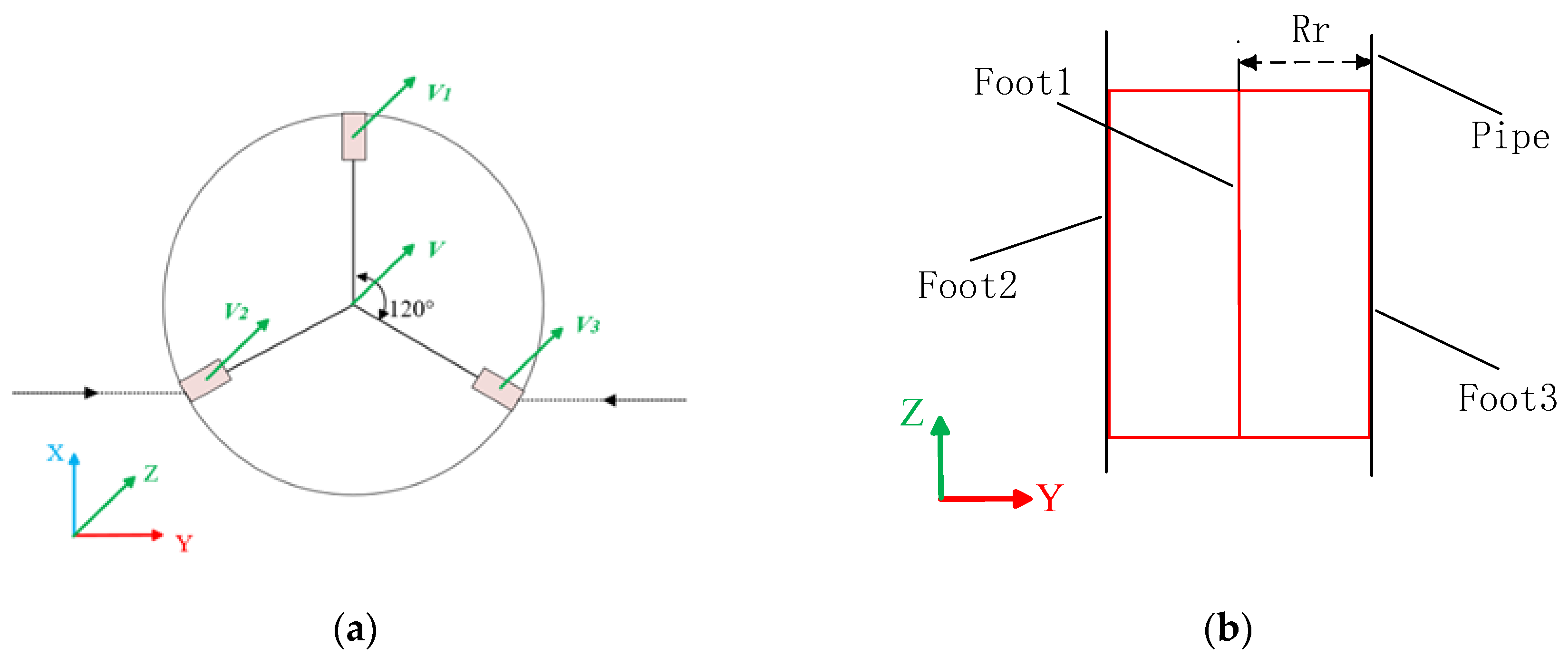
The default running state of the robot in the straight pipe is shown in the diagram. According to the section shown in the figure, if the width of the track is ignored and the robot’s track is regarded as a rigid body, there are only three contact points between the robot and the inner wall of the pipe on the section. Abstract the robot into a rectangle and make an overhead view of the motion inside the tube, as shown in Figure 3. The boundary of the left and right sides of the rectangle is the robot foot 3 and the robot foot 2, and the center line of the rectangle is the robot foot 1. Thus, in the straight pipeline, the boundary on both sides of the rectangle is also the point of contact between the robot and the pipeline. The center of the robot coincides with the central axis of the pipeline. Meanwhile, the three-foot velocity of the robot remains the same. Let the three-legged velocity be v1, v2 and v3 respectively, and the center velocity of the robot be v, thus:
v 1 = v 2 = v 3 = v
In the 2D analysis, assuming that the pipeline is an ideal bend pipe, divide the robot turning motion into two steps, the first step is to enter the elbow from the straight pipe, and the second step is to move in the elbow, which will be analyzed separately below.
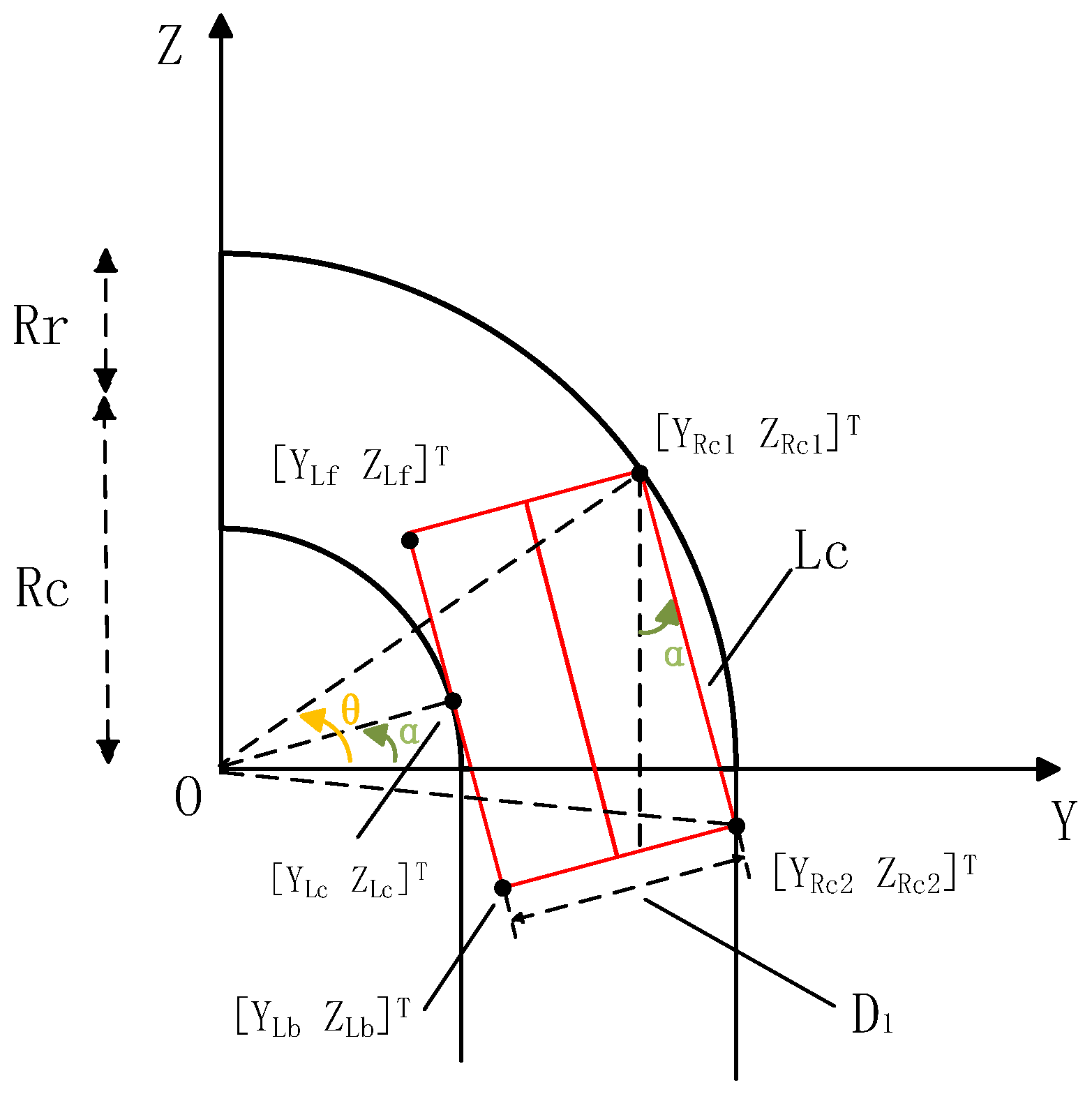
As shown in the Figure 4, in the process of the robot entering the bent pipe from the straight pipe, restricted by the spatial constraints of the curves, the contact point between the robot’s three driving modules and the pipe will be reduced, and the central of the robot no longer coincide with the central axis. The following begins to analyze the coordinates of the three crawlers contact points. The contact points of the crawlers are defined as [ Y L C , Z L C ] T , [ Y R C 1 , Z R C 1 ] T , [ Y R C 2 , Z R C 2 ] T .The contact point of the Foot1 and the pipe have different quantity for the different position, defined as [ Y T C 1 , Z T C 1 ] T , [ Y T C 2 , Z T C 2 ] T …. Define the left vertex of rectangle is [ Y L f , Z L f ] T , [ Y L b , Z L b ] T and the right vertex of rectangle is [ Y R f , Z R f ] T , [ Y R b , Z R b ] T . In the process of crossing a bent pipe, the two vertices on the right side usually coincide with the contact points.
As shown in Figure 4, Specifies that the line from the end of the rectangle to the origin is at an angle of θ to the Y-axis, α is the angle between the straight line from intersection point [ Y L C , Z L C ] T to origin O and the Y axis. R c is the distance from the axis of the pipe to the origin. R is the pipe radius, and R r is the horizontal position of the pipe center axis to the crawler contact point. The relationship between R and Rr is as shown.
Obtained by the cosine law, as in Figure 5, R = 2 3 3 R r , then the coordinates of each contact point can be expressed as:
[ Y R C 1 , Z R C 1 ] T = [ ( R c + R r ) cos θ   , ( R c + R r ) sin θ ] T
[ Y L C , Z L C ] T = [ ( R c R r ) cos α   , ( R c R r ) sin α ] T
[ Y R C 2 , Z R C 2 ] T = [ ( R c + R r )   ,   ( R c + R r ) sin θ ( L c ) cos α ] T
One thing to note is, the direction of the left boundary of the rectangle is the same as the tangential direction of the inner surface of the pipe, so the line from pointcuts to the origin is perpendicular to the left boundary of the rectangle.
Therefore, the equation about the line of the right boundary of the rectangle can be got:
Z = ( L c ) cos α ( R c + R r ) ( cos θ 1 ) ( Y R c R r ) + ( R c + R r ) sin θ ( L c ) cos α
According to the principle that the slope of the parallel line is the same, the straight line equation of the left boundary line of the rectangle is:
Z = ( L c ) cos α ( R c + R r ) ( cos θ 1 ) [ Y ( R c R r ) cos α ] + ( R c R r ) sin α
According to the equations of the two parallel lines, the distance between them can be obtained as:
D 1 = | 2 R r ( L c ) ( cos α ) 2 ( R c + R r ) ( cos θ 1 ) + 2 R r sin α | ( ( L c ) cos α ) 2 + [ ( R c + R r ) ( cos θ 1 ) ] 2
sin α = R c + R r ( 1 cos θ ) L c
The above formula shows that in the process of the robot entering the bend pipe from the straight pipe, the distance between the robot crawler changes with the movement of the robot, which describes the conditions that the robot needs to meet during the bending process.
Considering the different stretching state of the robot’s three crawler feet, the front side of each crawler foot of the robot is not aligned. The robot model is abstracted from a rectangle to a parallelogram. As shown in Figure 6, the robot adds an angle β , point [ Y R C 2 , Z R C 2 ] T can be derived by
[ Y R C 2 , Z R C 2 ] T = [ ( R c + R r )   ,   ( R c + R r ) sin θ ( L c ) cos α ] T
The equation of the right boundary line is:
Z = L sin α ( R c + R r ) ( cos θ 1 ) ( Y R c R r ) + ( R c + R r ) s i n θ L sin α
The equation of the left boundary line is replaced by:
Z = L sin α ( R c + R r ) ( cos θ 1 ) ( Y ( R c R r ) cos α ) + ( R c R r ) s i n α
The straight-line distance of the two boundaries is replaced by:
d 1 = | 2 R r ( L c ) ( cos α ) 2 ( R c + R r ) ( cos θ 1 ) + 2 R r sin α | ( ( L c ) cos α ) 2 + [ ( R c + R r ) ( cos θ 1 ) ] 2
sin α = R c + R r ( 1 cos θ ) L c
Since the abstract model is a parallelogram, the constraints of the robot change, and the result is as follows:
D 1 = d 1 sin β
When the robot point [ Y R C 2 , Z R C 2 ] T enters the first quadrant of the YOZ coordinate plane, it means that the robot has completely entered the elbow and is analyzed below:
For this, the coordinate of [ Y R C 1 , Z R C 1 ] T , [ Y L C , Z L C ] T in Figure 7 have not changed, as shown in (2) and (3), obtained by the triangle formula:
L c 1 = ( R c + R r ) sin ( θ α )
sin γ = L c L c 1 R c + R r
[ Y R C 2 , Z R C 2 ] T = [ ( R c + R r ) cos ( α γ )   ,   ( R c + R r ) sin ( α γ ) ] T
The right boundary line can be recalculated:
Z = sin θ sin ( α γ ) cos θ cos ( α γ ) [ Y ( R c + R r ) cos θ ] + ( R c + R r ) sin θ
Therefore, the constraint condition of the robot moving in the bend pipe can be equivalent to the distance between the left and right sides of the rectangle, calculated from the point to the straight line distance:
d 2 = | sin θ sin ( α γ ) cos θ cos ( α γ ) [ 2 R r cos θ ] + ( R r + R c ) ( sin θ sin α ) | [ cos θ cos ( α γ ) ] 2 + [ sin θ sin ( α γ ) ] 2
According to the mechanical structural characteristics of the robot, the constraints in the elbow are
D 2 = d 2 sin β
Among them, the degree of α and β are determined by the degree of the robot’s crawler foot contractility.
Different degrees of contraction of the foot two and the foot three may result in the same beta angle. At the same time, the size of the alpha angle is also related to the degree of foot 2 and foot 3 contraction. When the optimal stretching condition of foot 2 and foot 3 is obtained, the position of foot 1 can be obtained according to the robot shape, and the velocity relation of the three legs can be further obtained according to the position at this time. Therefore, how to get the optimal scaling conditions becomes an important problem to be solved.
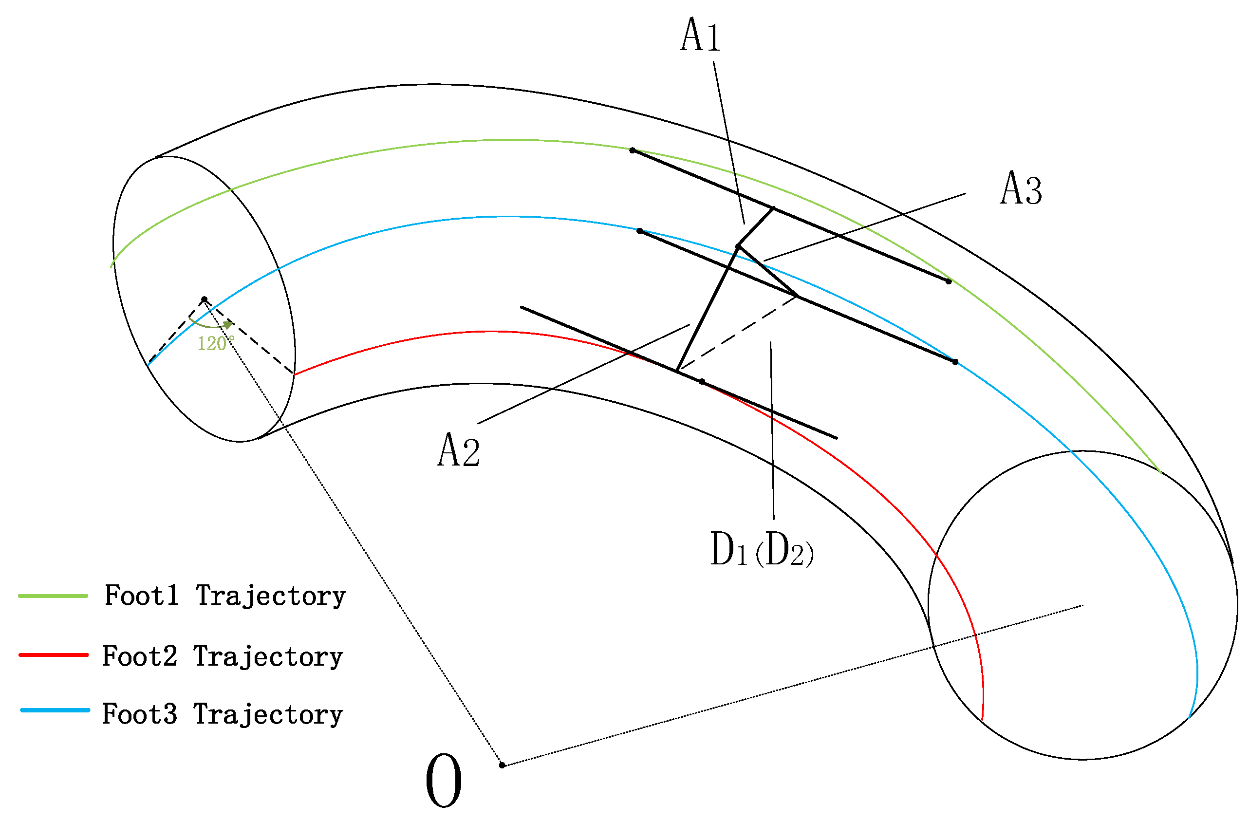
Figure 8 shows the movement state of the robot in the bend pipe. The red and blue lines represent the movement path of the robot Foot 2 and the Foot 3 in the tube. It can be known from the mechanical structure of the robot that if the two crawler modules motion path of the robot in the tube is obtained, the movement path of the third crawler can be obtained by the constraint of the pipeline itself.
Assume that the distance from the three crawlers to the center of the robot is L1, L2, L3, the angle between the two is 120°, obtained from the Law of Cosines:
( L 2 ) 2 + ( L 3 ) 2 2 ( L 2 ) ( L 3 ) cos 120 ° = d 2
In the above equation, d represents d1 in the Figure 6, d = D sin β , and D represents D1 or D2 in the Figure 8.
In order to combine the degree of expansion of the crawlers with the constraints, the relationship between L and the expansion of the telescopic rod is analyzed below:
Figure 9 is an abstract view of the crawlers and the main frame, ignoring the width of the main body bracket, X is the distance of the telescopic rod device, the length of the red line is a1, representing part of the length of the frame; A1 is the length of the whole frame. The green line c represents the distance between the frame and the telescopic rod device on the central base unit, ε is the angle of the frame and the central base unit. Establish the relationship between X and L:
ε = cos 1 x 2 c 2 ( a 1 ) 2 2 c ( a 1 )
L = A 1 sin ε
δ and ε are obtained in the same way, assume the change of the telescopic rod device is , and the relationship of the angle β and the extension length of the telescopic rod device.
a [ cos ε cos ( ε + d ε ) ] = I n c r e m e n t a [ cos ε cos ( ε + d ε ) ] = r e d u c t i o n I n c r e m e n t + r e d u c t i o n = C h a n g e _ v a l u e
Assuming the value of Change value is ex, thus,
cos β = e x e x 2 + d 2
e x 2 + d 2 = D
The relationship between the angles β, D and the length x of the putter is established.

2.3. The Analysis of the Robot Telescopic Rod Device

By analyzing the constraints of the robot when cornering, the above-mentioned expansion and contraction of the robot crawler at different positions has been analyzed. Further analysis of the above results, in order to obtain the ratio of the crawler modules speed of the robot in operation, it should be known that the position of the contact point between the track and the pipe.
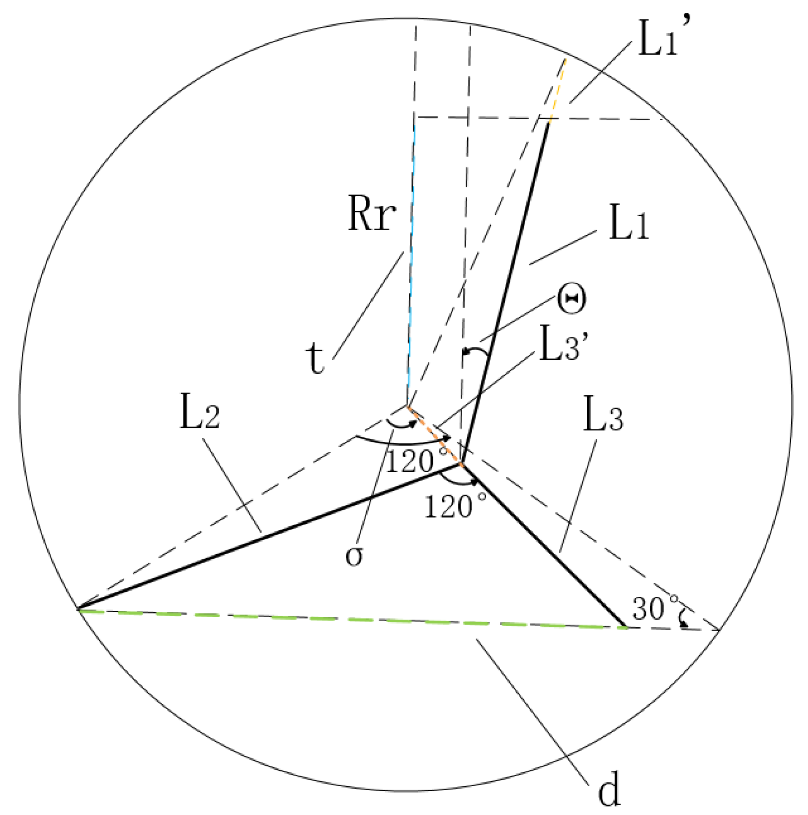
It can be analyzed from the figure above, when the pipe is perpendicular to the robot crawler modules, the friction of the track foot is maximized and the motor traction is maximized. As shown in Figure 10, when the robot is in motion, in order to obtain sufficient power, the Foot 3 is always perpendicular to the inner wall of the pipe. Since the Foot 2 has a contact point with the bent pipe, and the line of the Foot 2 is the tangent of the inner wall, the section of the pipe is taken from the tangent point position, and d is the distance between the Foot 2 and the Foot 3. Thus, the equations can be deduced:
d 2 = ( L 2 ) 2 + ( L 3 ) 2 2 ( L 2 ) ( L 3 ) cos 120 °
( 3 R r d ) 2 + R r 2 2 ( 3 R r d ) R r cos 30 ° = ( L 3 + L 3 )
σ = 120 ° arccos [ R r 2 + ( L 3 + L 3 ) 2 ( 3 R r d ) 2 2 R r ( L 3 + L 3 ) ]
d 2 = ( R r ) 2 + ( L 3 + L 3 ) 2 2 ( L 3 + L 3 ) R r cos σ
Combine the above four formulas, in the case that D is known, the length of L2 and L3 maintained at any time in the bending motion is known. Therefore, the trajectory of the robot center in the pipeline can be known. Since the mechanical structure with 120° difference between the three crawlers of the robot, after obtaining the position of the two feet and the center of the robot, the intersection of the third foot and the pipe wall can be obtained according to the geometric principle.
Θ = 180 ° σ arccos R r 2 2 ( L 3 ) ( L 2 )
R r 2 = ( L 1 + L 1 ) 2 + ( L 3 ) 2 2 ( L 3 ) ( L 1 + L 1 ) cos ( σ + Θ 60 ° )
t = L 1 cos Θ L 3 cos ( σ 60 ° )
The distance between the intersection of Foot 1 and the pipe to point O is
F 1 2 = R r 2 + t 2 2 ( R r ) t cos ( 90 ° + arccos R c t )
The distance between the intersection of Foot 2, 3 and the pipe to point O is
F 2 2 = R r 2 + R c 2 2 R r R c cos 30 ° F 3 2 = R r 2 + R c 2 2 R r R c cos 150 °
The speed of the three crawler modules can be obtained by:
v 1 : v 2 : v 3 = F 1 : F 2 : F 3
Therefore, the formula of the center deflection angle of the robot (the deviation angle of the robot gyroscope) and the output velocity at the time of turning is obtained:
v = G · α
In the formula, v is the velocity matrix of 3 * 1, G is the weighted transpose of matrix [v1, v2, v3], which is the relation matrix between velocity and angle, and α is the angle constant. According to the above formula, G is derived as [F1, F2, F3] T. Therefore, the corresponding output speed of the robot can be obtained by monitoring the angle of the robot gyroscope at each moment. Similarly, the robot’s bending algorithm can be extended to increase the degree of bend pipe of the pipeline from 90° to a larger angle. In essence, the robot can be considered to pass through a part of the 90° pipe and make changes to Rc and Rr. Simulation and experimental fitting of the algorithm are carried out below.
The degree of bend pipe can be defined as follows: When the robot moves forward from the straight pipe into the elbow, and then leaves the elbow and enters the straight pipe, the angle between the center lines of the two straight pipes.

3. Experiment and Analysis

3.1. Simulation Conditions and Results

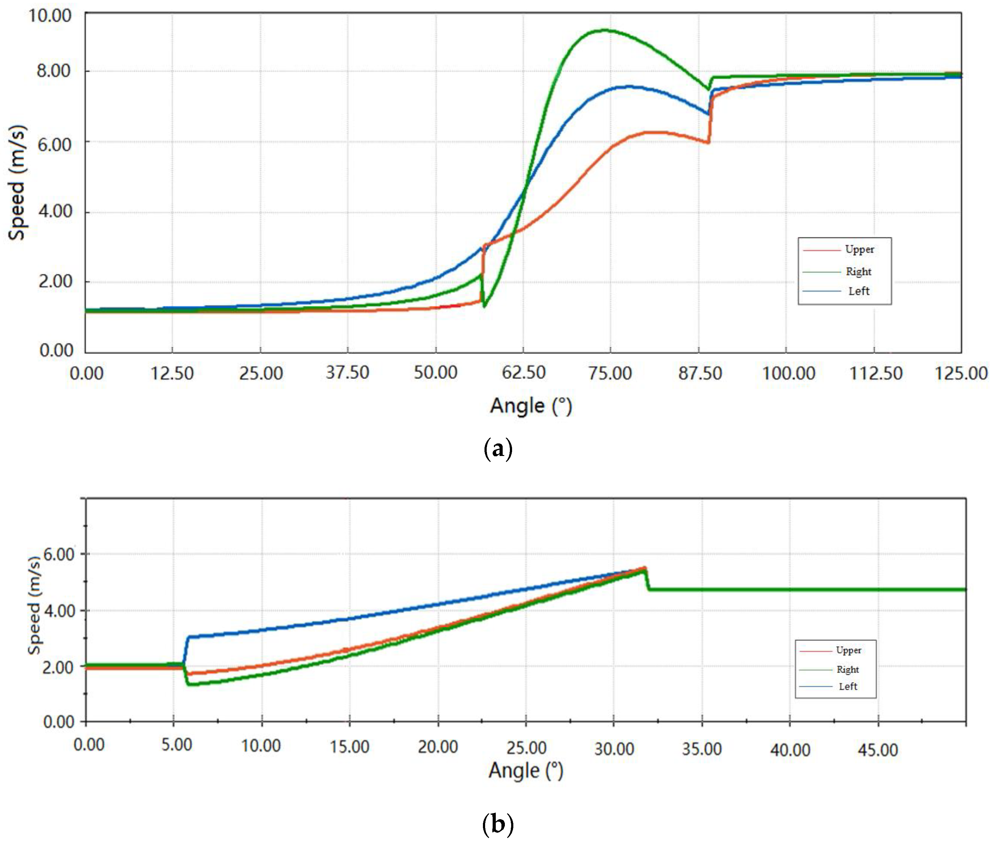
In this section, we use MATLAB to simulate the robot’s 90° bending speed according to the above formula, so as to determine whether the above bending algorithm conforms to the actual motion process. Through simulation, we get the robot’s speed when it passes through the straight pipe and the three-legged crossing speed on the 90° curve. In order to meet the more extensive comparison and application, we simultaneously simulated the relationship between the three-legged velocity and the offset angle of the robot through the curves of 150° and 120°. The simulation results are as follows.
Default parameters: The length of the robot is 530 mm, the width of the robot is 400 mm, the thickness of the robot’s track is 177 mm, the radius of the pipe is 1100 mm, and the distance from the center of the pipe to the center of the bend is 2200 mm. The following Figure 11a,b respectively simulates the running speed in the straight pipe and the three-legged running speed in different curved corners.
Figure 11a shows the offset angle and velocity curve when the degree of bend pipe is 90°; Figure 11b is the curve of the offset angle and velocity when the degree of bend pipe is 150°, so the gyroscope can pass through the curve only after the offset is 30°. By analyzing the simulation data, it can be seen that at an angle of 90°, the single-foot velocity of the robot almost changes linearly as it moves in the pipeline, and it is accelerated slowly all the time during the bending process. However, when the degree of bend pipe is greater than 90°, the robot’s running speed is no longer linear, and the greater the degree of bend pipe, the less nonlinear the robot’s three-legged speed will be. For the outer feet, the change in velocity is more pronounced than for the inner feet. The simulation shows that there is a jump point for the three-legged velocity, which is caused by the change of the robot from incomplete entry to complete entry of the bend. The jump phenomenon decreases with the increase of the curve of the pipe.
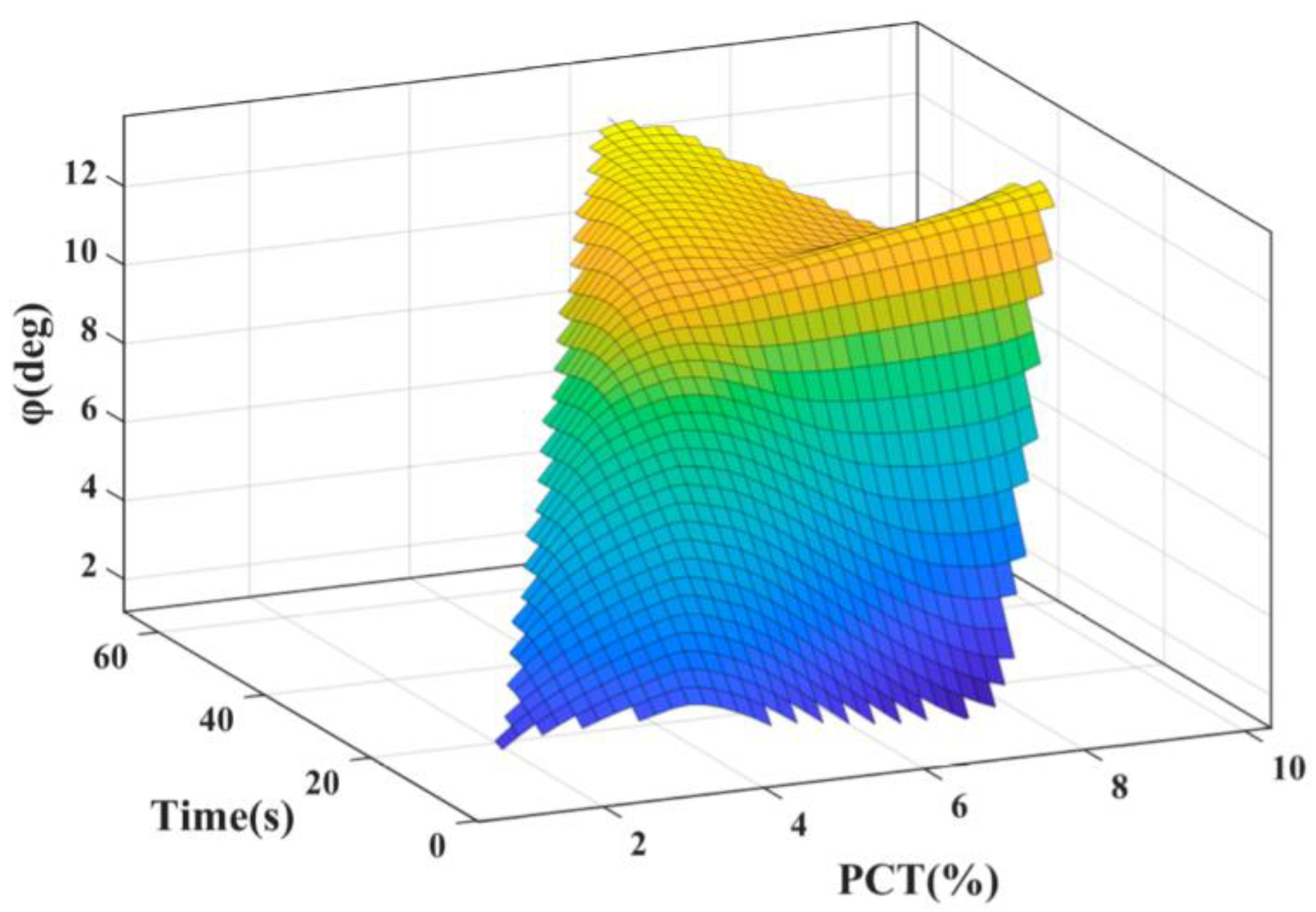
The rotating power source of the robot comes from the driving force provided by the motor, and the traction force of a single motor is 117.4 N. To model the motor driving force, time and rotation angle, when the robot is running in a stable straight line, increase or decrease the force of the two motors at the bottom by 1%. The virtual angle sensor detects the stable deflection angle of the robot and monitors the time count. The deviation of the force (PCT, the difference of the traction force of the motors on both sides) is increased with time to simulate the stable deflection angle of the specific robot and the time required for it without external force. The modeling result is shown in Figure 12. The simulation results prove that when the PCT does not exceed 10%, the maximum stable rotation angle φ of the robot without external force is 14°, so the modeling meets the requirements of the robot to corner. The simulation result is shown in Figure 12.

3.2. Experimental Environment and Control Strategy

The specific parameters of the robot used in this experiment refer to the above content of the article. In order to verify the rationality of the algorithm, we conducted field experiments in a steel pipe with an inner diameter of 1100 mm. The robot runs repeatedly in a three-meter-long pipeline to verify our theory.
The overall control strategy is as follows: The core control strategy is to build a model of the robot deflection angle and the corresponding main control output duty cycle. The main control chip of the robot adopts RT1052 with a main frequency of 700 MHz. After the robot enters the bend, the pressure value of the three-track thin film pressure sensor group changes. The thin film pressure sensor group is a 2 * 2 thin film pressure sensor matrix, and the specific direction of the caterpillar force and the pipe wall force is obtained according to the sensor position with the largest and second largest pressure value. When the pressure difference between the front and rear pressures expands to the set threshold, it is considered that the front half enters the bend pipe, and the corresponding crawler foot is raised to stabilize the three-leg pressure ratio. Synchronously turn on the gyroscope mounted in the robot to measure the offset angle, and combine the data from the film pressure sensor group to limit the three-track foot pressure within a reasonable range. According to the above algorithm and the offset angle value, the ideal three-track foot speed is calculated for the current angle. The main control chip outputs the speed value to the motors by controlling the duty ratio, and drives the three motors to rotate to realize the movement in the tube. The robot uses incremental PID to control the three-track feet to construct a closed-loop model between the output duty cycle and the speed of the three-track feet. The encoder obtains the actual crawler foot speed at the crawler foot, feeds the actual speed back to RT1052 to calculate the deviation, and obtains the control increment according to the accumulation of multiple deviations to control the change trend of the current output duty cycle. In this way, an adaptive model between the offset angle of the robot and the output duty cycle of the main control chip is constructed, which realizes the controllability during the entire operation.

3.3. Experimental Results and Analysis

The speed encoder is used to collect the speed of the tripod, and the membrane pressure sensor is used to collect the pressure value of the tripod, and the result is recorded in the SD card carried by the main control chip of the robot. The data passing through the 90° pipeline is as follows:
In Figure 13a is the data collected during the operation of the robot’s three-track foot membrane pressure sensor. The red, green and blue curves represent the upper track pressure curve, the lower right track pressure curve, and the lower left track pressure curve. The pressure on the left crawler at the lower end is the largest, while the pressure on the upper crawler is the smallest, which is consistent with the aforementioned analysis. During the entire cornering process, the ratio of the three-legged pressure of the robot is basically stable. It can be proved that the algorithm guarantees the stability of the robot.
Figure 13b is the speed change graph of the three crawler feet of the robot in actual operation, and the data sampling rate is 10 Hz. The figure shows the average value of time and speed obtained after several experiments. The three red, green and blue curves represent the upper crawler speed value curve, the lower right crawler speed value curve, and the lower left crawler speed value curve. The robot can pass through curves in an average of 6 s, and the overall speed fluctuations are small, thanks to the stable speed control of PID. The actual result is similar to the simulation result. According to our analysis, the reasons for the slight difference between the simulation results and the experimental results are as follows: The actual robot is not an absolute rigid body structure, and some vibration and separation when it contacts the pipe wall is unavoidable. This will cause a small amount of interference in the data collection of the encoder and affect the judgment of the overall speed. In addition, the inner wall of the pipeline is not in an ideal state, and there may be some problems (such as rust) on the surface of the pipeline, which may affect the judgment of the external force of the robot when it passes by. However, the simulation results and the experimental results tend to be basically the same. The algorithm shows good superiority in practical applications, allowing the robot to pass reasonably when the electric telescopic rod cannot adapt to the change of pipe diameter.

4. Conclusion and Future Work

This paper solves the adaption problem of the connection structure between the crawler foot of the crawler-type detection robot and the robot body to the internal changes of the pipeline, and proposes a cornering algorithm based on the above-mentioned robot. This algorithm is suitable for any arc and any size of bend. The tube is universal. This algorithm allows the wall-pressing large-scale crawler pipeline robot to run smoothly in the pipeline, laying a good kinematic foundation for pipeline flaw detection.
Based on the above robot model, this paper proposes a large-scale in-pipe robot with an electronic telescopic rod device instead of spring contractile mechanism. This paper sets up a two-dimensional and three-dimensional idealized model for the robot by studying a type of in-pipe inspection robot as well as analysis of the cornering process of the robot mentioned above. We theorized an in-pipe cornering algorithm for a large-scale three-legged crawler in-pipe inspection robot based on the two-dimensional and three-dimensional analysis. Based on the constraint condition of the pipeline this algorithm is capable of stabilizing the robot by adjusting the length of its telescopic rod device, accomplishing idealized cornering by offering different velocities to the three independent legs depend on the position of the three legs. On the basis of analyses, the robot is capable of traveling through the bent pipe pipes successfully—provided that it completes the process between the straight and bent pipe. We are able to gain the information of the robot’s own real-time width based on the constraint condition, guaranteeing enough traction by controlling its own contracted state to assure that the robot works continuously and steadily in pipelines, which is different from common small sized robots with self-adaptability. In this paper, a simulation and a field experiment of the algorithm are also carried out. The experimental results of the three-legged pressure and operating speed prove that the algorithm can be applied to the pipeline robot and that it has good stability. In addition, the algorithm ensures that the pressure ratio of the robot’s three crawlers is constant during the cornering process, which proves that the algorithm has good stability.

Author Contributions

Conceptualization, L.X. and J.Z.; methodology, L.X.; software, J.Z.; validation, L.X., L.Z. and J.Z.; formal analysis, K.K.; investigation, K.K.; resources, L.Z.; data curation, L.X.; writing—original draft preparation, J.Z.; writing—review and editing, L.Z.; visualization, K.K.; supervision, L.Z.; project administration, K.K.; funding acquisition, L.Z. All authors have read and agreed to the published version of the manuscript.

Funding

This work was supported by the Fundamental Research Funds for the Central Universities (2019ZRJC005).

Conflicts of Interest

The authors declare no conflict of interest.

References

  1. Song, Z.; Ren, H.; Zhang, J.; Ge, S.S. Kinematic Analysis and Motion Control of Wheeled Mobile Robots in Cylindrical Workspaces. IEEE Trans. Autom. Sci. Eng. 2015, 13, 1207–1214. [Google Scholar] [CrossRef]
  2. Jun, C.; Deng, Z.Q.; Jiang, S.Y. Study of Locomotion Control Characteristics for Six Wheels Driven In-Pipe Robot. In Proceedings of the IEEE International Conference on Robotics & Biomimetics, Shenyang, China, 22–26 August 2004. [Google Scholar]
  3. Bandala, A.A.; Maningo, J.M.Z.; Fernando, A.H.; Vicerra, R.R.P.; Antonio, M.A.B.; Diaz, J.A.I.; Ligeralde, M.; Mascardo, P.A.R. Control and mechanical design of a multi-diameter tri-legged in-pipe traversing robot. In Proceedings of the IEEE/SICE International Symposium on System Integration, Paris, France, 14–16 January 2019. [Google Scholar]
  4. Li, T.; Ma, S.; Li, B.; Wang, M.; Wang, Y. Design and locomotion control strategy for a steerable in-pipe robot. In Proceedings of the IEEE International Conference on Mechatronics and Automation (ICMA), Beijing, China, 2–5 August 2015. [Google Scholar]
  5. Kwon, Y.S.; Yi, B.J. Design and Motion Planning of a Two-Module Collaborative Indoor Pipeline Inspection Robot. IEEE Trans. Robot. 2012, 28, 681–696. [Google Scholar] [CrossRef]
  6. Kakogawa, A.; Ma, S. Speed analysis for three driving modules of an in-pipe inspection robots for passing through bent pipes. In Proceedings of the IEEE International Conference on Robotics & Biomimetics, Bali, Indonesia, 5–10 December 2014. [Google Scholar]
  7. Singh, P.; Ananthasuresh, G.K. A Compact and Compliant External Pipe-Crawling Robot. IEEE Trans. Robot. 2012, 29, 251–260. [Google Scholar] [CrossRef]
  8. Dertien, E.C.; Foumashi, M.M.; Pulles, K.; Stramigioli, S. Design of a robot for in-pipe inspection using omnidirectional wheels and active stabilization. In Proceedings of the IEEE International Conference on Robotics and Automation (ICRA), Hong Kong, China, 31 May–7 June 2014. [Google Scholar]
  9. Wu, Y.; Noel, A.; Kim, D.D.; Youcef-Toumi, K.; Ben-Mansour, R. Design of a maneuverable swimming robot for in-pipe missions. In Proceedings of the IEEE/RSJ International Conference on Intelligent Robots & Systems, Hamburg, Germany, 28 September–2 October 2015; pp. 4864–4871. [Google Scholar]
  10. Yamamoto, T.; Konyo, M.; Tadakuma, K.; Tadokoro, S. A self-locking-type expansion mechanism to achieve high holding force and pipe-passing capability for a pneumatic in-pipe robot. In Proceedings of the IEEE International Conference on Robotics & Automation, Singapore, 29 May–3 June 2017. [Google Scholar]
  11. Kim, D.W.; Park, C.H.; Kim, H.K.; Kim, S.B. Force adjustment of an active pipe inspection robot. In Proceedings of the Iccas-sice International Joint Conference, Fukuoka, Japan, 18–21 August 2009; pp. 3793–3797. [Google Scholar]
  12. Roh, S.G.; Choi, H. Differential-drive in-pipe robot for moving inside urban gas pipelines. IEEE Trans. Robot. 2005, 21, 1–17. [Google Scholar]
  13. Oya, T.; Okada, T. Development of a steerable, wheel-type, in-pipe robot and its path planning. Adv. Robot. 2005, 19, 635–650. [Google Scholar] [CrossRef]
  14. Kakogawa, A.; Ma, S.; Hirose, S. An in-pipe robot with underactuated parallelogram crawler modules. In Proceedings of the 2014 IEEE International Conference on Robotics and Automation (ICRA), Hong Kong, China, 31 May–7 June 2014. [Google Scholar]
  15. Harish, P.; Venkateswarlu, V. Design and Motion Planning of Indoor Pipeline Inspection Robot. Int. J. Innov. Technol. Explor. Eng. (IJITEE) 2013, 3, 41. [Google Scholar]
  16. Zhang, Y.; Zhang, M.; Sun, H.; Jia, Q. Design and motion analysis of a flexible squirm pipe robot. In Proceedings of the 2010 International Conference on Intelligent System Design and Engineering Application, Changsha, China, 13–14 October 2010; pp. 527–531. [Google Scholar]
  17. Park, J.; Hyun, D.; Cho, W.-H.; Kim, T.-H.; Yang, H. Normal-force control for an in-pipe robot according to the inclination of pipelines. IEEE Trans. Ind. Electron. 2010, 58, 5304–5310. [Google Scholar] [CrossRef]
  18. Tourajizadeh, H.; Rezaei, M.; Sedigh, A.H. Optimal control of screw in-pipe inspection robot with controllable pitch rate. J. Intell. Robot. Syst. 2018, 90, 269–286. [Google Scholar] [CrossRef]
  19. Zhao, W.; Zhang, L.; Kim, J.-W. Design and analysis of independently adjustable large in-pipe robot for long-distance pipeline. Appl. Sci. 2020, 10, 3637. [Google Scholar] [CrossRef]
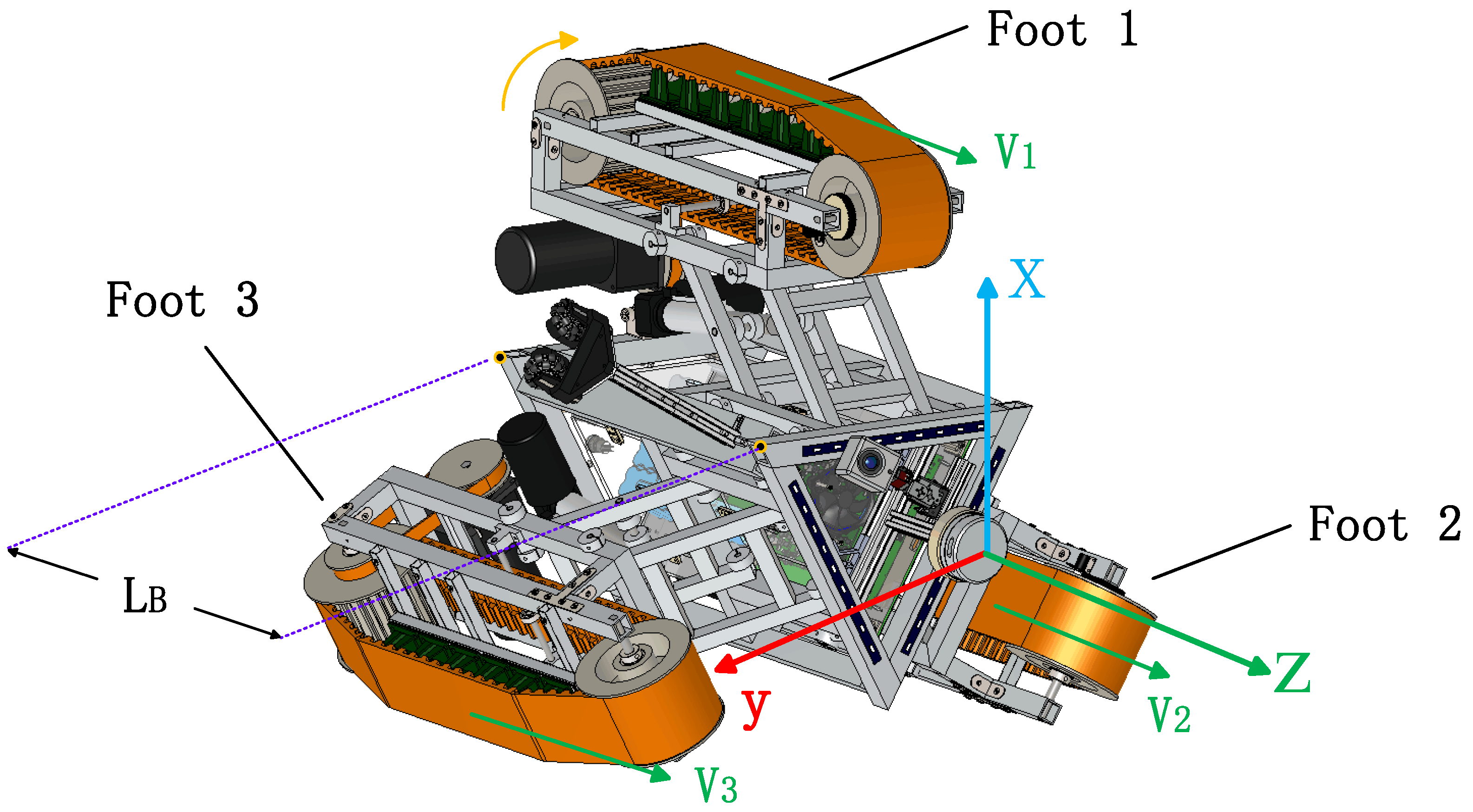
Figure 1. Solidworks rendering and parameter creation.
Symmetry 12 02016 g001
Figure 2. Overview of the robot.
Symmetry 12 02016 g002
Figure 3. Robot motion model in straight pipe, v 1 , v 2 , v 3 exits. (a) Cross-sectional view of the pipeline; (b) Contact between the crawler modules and the pipe on top view.
Symmetry 12 02016 g003
Figure 4. Rectangular model in the bent pipe.
Symmetry 12 02016 g004
Figure 5. The relationship about R and Rr on the cross-sectional.
Symmetry 12 02016 g005
Figure 6. The contact point of pipe and robot abstracted to parallelogram model when ZRC2 < 0.
Symmetry 12 02016 g006
Figure 7. The contact point of pipe and robot abstracted to parallelogram model when ZRC2 > 0.
Symmetry 12 02016 g007
Figure 8. The posture of robot in the bent pipe and the trajectory of each motion module.
Symmetry 12 02016 g008
Figure 9. A cross-sectional of the crawlers and the central base unit on top view.
Symmetry 12 02016 g009
Figure 10. The length of the telescopic rod device and the position of the LCR when moving in bent pipe.
Symmetry 12 02016 g010
Figure 11. (a) Simulation about the offset angle and velocity curve when the degree of bend pipe is 90°; (b) simulation about the curve of the offset angle and velocity when the degree of bend pipe is 150°. The red, blue and green colors respectively represent the full speed of the upper track, the left track and the right track at the lower end.
Symmetry 12 02016 g011
Figure 12. The simulation about angles of the robot with times and PCT.
Symmetry 12 02016 g012
Figure 13. (a) The experiment result about the pressure when the robots went through the bent pipe; (b) the experiment result about the speed when robots went through the bent pipe.
Symmetry 12 02016 g013
Publisher’s Note: MDPI stays neutral with regard to jurisdictional claims in published maps and institutional affiliations.