Article

Renewable Energy System on Frequency Stability Control Strategy Using Virtual Synchronous Generator

1
State Key Laboratory of Reliability and Intelligence of Electrical Equipment, Hebei University of Technology, Tianjin 300130, China
2
Key Laboratory of Electromagnetic Field and Electrical Apparatus Reliability of Hebei Province, Hebei University of Technology, Tianjin 300130, China
3
Institute of Innovation and Circular Economy, Asia University, Taichung 41354, Taiwan
4
Department of Medical Research, China Medical University Hospital, China Medical University, Taichung 404322, Taiwan
5
Faculty of Economics and Management, Universiti Kebangsaan Malaysia, Bandar Baru Bangi 43600, Malaysia
6
Industrial Engineering Department, Gokongwei College of Engineering, De La Salle University, Manila 0900, Philippines
*
Author to whom correspondence should be addressed.
Symmetry 2020, 12(10), 1697; https://doi.org/10.3390/sym12101697
Submission received: 16 September 2020 / Revised: 7 October 2020 / Accepted: 9 October 2020 / Published: 15 October 2020

Abstract

:
This study constructs a novel virtual synchronous generator system based on a transfer function, and optimizes the parameters of the model by using the improved whale algorithm to improve the frequency control ability of virtual synchronous generator. Virtual synchronous generator technology helps to solve the problem that the integration of large-scale renewable energy generation into the power system leads to the deterioration of system frequency stability. It can maintain the symmetry of grid-connected scale and system stability. The virtual synchronous generator technology makes the inverter to have the inertia and damping characteristics of a synchronous generator. The inverter has the inertia characteristics and damps to reduce the frequency instability of high penetration renewable energy power system. The improved whale algorithm is efficient to find the best combination of control parameters and the effectiveness of the algorithm is verified by microgrid and power system. The results show that the proposed frequency coordination control scheme suppresses the frequency deviation of power system and keep the system frequency in a reasonable range.

1. Introduction

Renewable energy (RE), such as solar energy and wind energy, has the advantages of being clean and pollution-free. A large-scale development of RE such as solar energy and wind energy is increasingly valued for environmental reasons [1,2,3,4]. Karasoy et al. [5] argued the relationship between energy consumption and environmental pollution and proved the RE consumption reduces carbon emissions at any time scale. Anastasiadis et al. [6] presented the power network feasibility including solar power generation and wind power generation. Shankar et al. [7] presented the results of solar cooling thermal power plant to show the system proposed is suitable for industry and family needs. Stritih et al. [8] studied the solar energy storage and the results show that the economic and effective thermal energy storage is necessary. RE has shown practical value in the fields of power generation; especially, when it is integrated into the micro-grid that leads more advantages [9,10,11,12]. This is considered as an attractive substitute for fossil energy. The increase in the grid connection rate of renewable energy has brought the system instability problem. Therefore, the symmetry between the grid connection rate of renewable energy and the stability of the system should be maintained.
Synchronous generator (SG) has better inertia and damping characteristics to support the power system frequency [13]. Power electronic inverters have replaced SG in a large number in the renewable energy power generation system. The inverter has no inertia and damping characteristics and has a weak ability to adjust system fluctuations [14,15]. Renewable power generation has low inertia and results in serious frequency fluctuations [16,17,18]. The instability of the system limits the power transmission capacity [19,20,21,22]. This instability limits the RE penetration in power systems to limit grid de-carbonization [23,24]. In view of this problem, prior studies have put forward solutions to improve the RE penetration in the power system. One is to design a specific inverter control algorithm to make the inverter have the SG inertia characteristics and improve the stability of the system frequency [25,26,27]. This systematic control method is called virtual synchronous generator (VSG). For instance, Zheng et al. [28] presented VSG and control strategies were proposed, but parameters were not optimized. Intelligent algorithms have advantages in parameter optimization and are used in various problems of parameter optimization [29,30,31]. Magdy et al. [32] discussed the optimizing control parameters by using intelligent algorithm to improve the performance of control strategy. These studies are lacking to address and research on model optimization. Using intelligent algorithms to optimize model parameters enhances the performance of the model.
The objective is to propose a VSG control method based on algorithm optimization to improve the frequency stability of renewable energy power systems due to improving the stability of the renewable energy power system and promoting the use of clean energy. A VSG control structure and parameter optimization method are proposed and the optimal value of parameters is set by using the improved whale optimization algorithm (WOA). The contributions of this study are as follows: (1) A VSG-based systematic control method for RE power system inverter is developed. The method is beneficial to improve the system inertia and stabilize the system frequency; (2) the control parameters are optimized with an improved WOA; but the algorithm has few parameters, fast convergence speed, and high convergence accuracy; and (3) the effectiveness of the control strategy is validated on two experimental test models: one is a micro-grid system and the other is a large power system. The simulations show that the proposed VSG systematic control method has a better practical effect.
The rest of this study is arranged as follows. Section 2 is literature review, Section 3 introduces the VSG model, Section 4 introduces the configuration of the test model, Section 5 discusses and analyzes the experimental results, and the conclusion is in Section 6.

2. Literature Review

VSG improves the inertia and the frequency stability of the system. The proposed control strategy measures the disturbance and generate reference power. The proposed control strategy provides more inertia and disturbance attenuation for the inverter. Prior studies on VSG included system stability, grid connection, and optimal control [33,34,35,36].
VSG system stability studies the stability of control system and its influence on power system stability. In order to improve the system stability, for instance, Li et al. [33] studied the virtual damping link and root locus method, established the VSG small signal model, analyzed the relationship between control parameters and system stability, and designed the system parameters quantitatively. Chen and O’Donnell [34] argued a VSG comprehensive analysis based on a transfer function that was proposed to improve the performance. In the work of Shuai et al. [35], the safety and stability of the system are initially analyzed in qualitative consideration and proposed to use Lyapunov direct method to analyze the VSG transient angle stability. The adverse effects of reactive power circuits on system stability and the effects of different parameters on transient angle stability are analyzed, which provides a basis for system stability design. Du et al. [37] proposed a method to avoid mode approaching and divides the influence on the mode approaching. The relationship between VSG and power system stability is studied to guide the design. The expansibility needs to be further proven. Shi et al. [38] proposed a VSG self-adjusting parameter on control strategy when the system frequency oscillates; this leads to VSG increasing or decreasing the virtual inertia according to the virtual angular velocity. Virtual damping improves the frequency stability of microgrid, but at the same time increases the burden of energy storage system. Magdy et al. [39] presented a frequency coordination strategy based on optimal PID controller to optimize relevant parameters with intelligent algorithm and the control strategy leads to robustness. Hu et al. [40] argued the multiple VSG coordination control and joint use reduced the oscillation period and overshoot during transient response to enhance the operation performance and anti-interference ability. Ding et al. [41] analyzed the dynamic characteristics of the parallel capacitor photovoltaic power supply in depth, and proposed a VSG systematic control method to solve the problem that photovoltaic power supply cannot be used as a DC power supply due to the fluctuation.
VSG grid connected study means to pre synchronize the phase and reduce the impact of the inverter grid connected to the power system. There is a restriction relationship between the VSG response speed and the power output overshoot. For instance, Zhang et al. [42] showed the lumped interference is compensated by feedforward. A power controller for grid connection is proposed based on the linear active interference suppression control. A power controller for grid connection transmits the active power to the grid in time and avoids overshoot. The system has strong robustness. Wang and Sun [43] studied the imbalance phenomenon and expanded the application scenario of self-synchronous VSG strategy in the balanced power grid and the second-order generalized integrator is used to deal with the double frequency ripple component, which improves the accuracy of self-synchronization. Shi et al. [44] proposed a VSG integrated switching systematic control method and includes quasi synchronous algorithm and islanding monitoring algorithm. The integration method improves the reliability and quality of the power supply. In the energy storage research, the problems of capacity allocation and optimal control of energy storage system matching with VSG are discussed. Li et al. [33] studied the cascaded H-bridge converter technology and proposed a transformer free energy storage system. In the field of battery and supercapacitor, Fang et al. [45] proposed a hybrid system composed of the two to fulfill the gap in this study.
Prior studies on the VSG optimal control attempted to design a reasonable control structure ad optimize the relevant parameters to achieve the best control effect. For instance, in vector current control, Asrari et al. [46] proposed a VSG systematic control method to provide stable power transmission for an extremely weak AC power grid while the power grid voltage is unbalanced and the traditional control method has no corresponding measures, and the output current is distorted. Zheng et al. [47] proposed a new control method to solve and reduce the power system’s oscillation. The inertia of the traditional VSG rotor is fixed, which cannot meet the requirements of various operating environments. In order to solve this problem, Zeng and Su [48] proposed an adaptive adjustment method of rotor inertia. In the oscillation simulation, VSG adaptively changes the inertia of virtual rotor, so as to adjust the inertia of the whole system, making it more conducive to the stability of the system. The grid connected inverter controlled by VSG suffers the inherent low-frequency vibration. For instance, Liu et al. [49] and Cao et al. [50] studied the control scheme to solve the VSG low-frequency oscillation problem and the grid connection process is interfered by various factors. In traditional VSG, it is hard to eliminate these factors and results in performance degradation. Yu and Hu [51] studied the VSG auto disturbance rejection control method, which effectively improved the performance when connected to the grid.
To sum up, prior studies have proposed specific control strategies, but have not studied the optimal selection of control strategy parameters in depth. The control parameters have an important influence on the quality of control effects. Different parameter values have different control effects and a reasonable value of parameters is of great help to improve the control effect of the control strategy. A novel design of a VSG system is proposed. The power electronic inverter has the similar frequency support ability as SG by simulating the rotor and frequency modulation function of SG. The WOA is applied to optimize the control parameters of the controller, so that the controller achieves the best performance. The superiority of the proposed control scheme is verified by experiments.

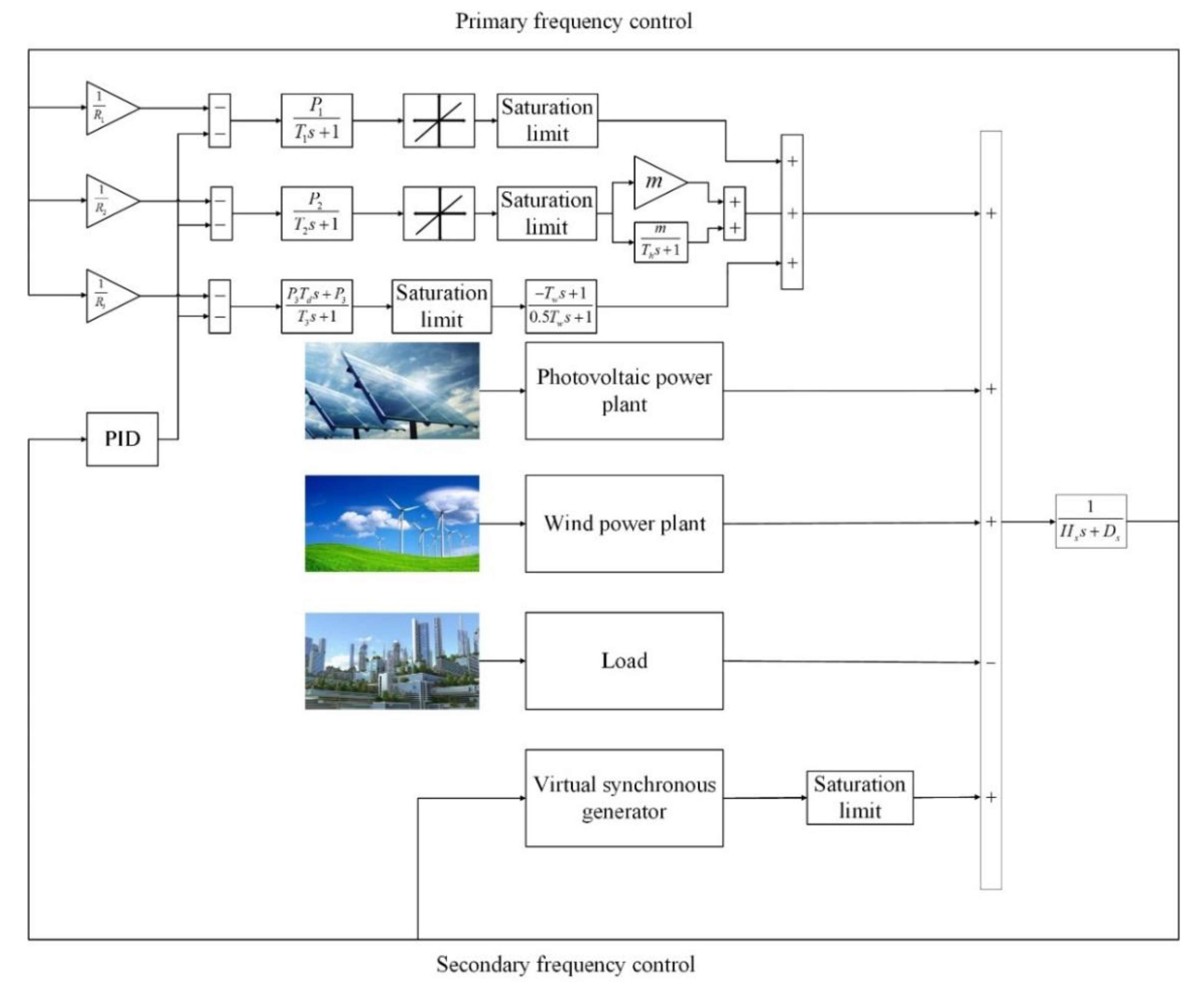
3. Virtual Synchronous Generator Model

RE has poor inertia and damping that leads to the undesired increase of frequency fluctuation [22]. VSG technology introduces a “virtual rotor” into the power electronic inverter, to create “simulated inertia” to dampen frequency fluctuations. The rotor of SG has the following energy relationship.
P M e c ( s ) P L o a d ( s ) = ( 2 H r s + D r ) f ( s )
H r is the inertia constant of the rotor, D r is the damping coefficient, P M e c is the change of input mechanical power, P L o a d is the change of load power, and f ( s ) is the frequency offset. Equation (1) presents the rotor inertia constant H r and damping coefficient D r which play an important role in stabilizing the system frequency. Under the same power deviation condition, the larger the rotor inertia is, the smaller the frequency deviation is. In time scale, the frequency of the SG regulating system includes three processes: Inertia response process, governor regulating process, and frequency regulator regulating process. When the system power is unbalanced, the power of the SG rotor is adjusted first, which depends on the energy stored in the rotor rotation. If a large frequency deviation is still caused, the system governor is activated and the governor regulates the system frequency by controlling the input mechanical power. The frequency regulator adjusts the system frequency in a longer time range, so that the frequency does not exceed the specified range. The functions of SG should be taken into account, so that designing VSG has the same functions as inertia regulation, governor regulation, and frequency regulator regulation of SG.

3.1. Virtual Inertia and Damping Characteristics

The inertia of SG is supported by the rotor, so the function of “virtual rotor” should be designed in the VSG. The function of the virtual rotor is described by Equation (2).
P r e f = ( H v s + D v ) Δ f
P r e f is the reference power output, H v is the VSG virtual rotor virtual inertia, and D v is the virtual damping coefficient. VSGs have the characteristics of SG rotor by designing “virtual rotor” with Equation (2).

3.2. Virtual Primary Frequency Modulation and Virtual Secondary Frequency Modulation

The SG has a governor device to adjust the input mechanical power after the frequency offset, and compensate the power and frequency offset proportions. The corresponding proportional link is designed to achieve the VSG primary frequency regulation function. The secondary frequency modulation of SG is to adjust the frequency of system to the rated value, so the integration link is designed to play the role in a longer time span and realize the role of virtual secondary frequency modulation. The control relationship is described by Equation (3).
Δ P = K 1 Δ f + K 2 s Δ f
Δ P is the power value of the virtual primary frequency modulation and virtual secondary frequency modulation. K 1 and K 2 are virtual primary and virtual secondary gain, respectively.

3.3. Inverter Model

The output power of the power electronic inverter follows the command signal through pulse width modulation. The response speed of power electronic inverter is faster compared with SG. Based on this feature, the inverter is modeled as an inertial link, as shown in Equation (4). T i is the time constant.
G ( s ) = 1 T i s + 1

3.4. Virtual Controller Design

3.4.1. Structure Design of Virtual Controller

The structure of virtual controller not only affects the VSG system stability, but also has a decisive influence on the control performance. The structure of virtual controller includes not only virtual rotor, virtual primary frequency modulation, and virtual secondary frequency modulation, but also an independent integration link. This design is to give full play to the ability of the controller to adjust the system frequency and improve the frequency stability of the system. The schematic of the controller is shown below.
In Figure 1, K 3 is the gain of the controller integration link, and other parameters are as described.

3.4.2. Parameter Design of Virtual Controller

The parameter selection of the virtual controller has an important influence on the performance of the virtual controller. The VSG virtual controller has three important parameters, namely, the virtual main controller coefficient, the virtual auxiliary controller coefficient K 2 , and the integral controller coefficient K 3 , these parameters not only affect the VSG frequency regulation effect, but also affect the stability of the whole control system. Conventional methods are hard to determine the best value of these three key parameters. The improved WOA is used to find the optimal combination of parameters to obtain the optimal control performance.
  • Example description
Equation (5) is the transfer function of the virtual controller. The parameters of the controller are set according to the results of the improved whale algorithm to achieve the optimal control performance. The issue of frequency control in power systems has been studied, and the object of VSG frequency control is to minimize the frequency deviation [52,53]. Therefore, the objective function of the improved WOA is the sum of the squares of the frequency offset in the steady state, and in consideration of the dynamic performance of the system, the frequency offset value in the dynamic process is added to the objective function, and the weighted sum of the two is the final objective function value. The final form of the objective function is shown in Equation (6).
G ( s ) = ( H v s + D v ) ( K 1 + K 2 s ) + K 3 s T i s + 1
O b f = m 1 0 t s i m ( Δ f ) 2 + m 2 t min t max ( Δ f ) 2
In Equation (6), m 1 and m 2 are weighting coefficients and satisfy m 1 + m 2 = 1 , t s i m is simulation time, and this time does not include transient time, t min is transient start time, t max is transient end time.
2.
Whale Optimization Algorithm
WOA is a novel heuristic algorithm, which is inspired by humpback whale’s bubble hunting strategy [54]. WOA has the advantages of few parameters and strong global optimization characteristics. It is applied here to the controller design to find the optimal controller parameters. The WOA consists of the following main processes.
(1) Random search
The mathematical expression of the hunt process is as follows.
D = | X i ( t ) E X r |
X i ( t + 1 ) = X r B D
In the Equation, X r represents a position randomly selected from the current group position; X i stands for the position vector of the individual; t stands for the current number of iterations; Equation (7) is the distance between the individual and the random individual. B and E are coefficients.
B = 2 a r a
E = 2 r
a decreases as the number of iterations increases; r is a random number between 0 and 1.
(2) Siege predation
Humpback whales shrink to encircle prey as follows.
D = | E X b e s t ( t ) X i ( t ) |
X i ( t + 1 ) = X b e s t ( t ) B D
X b e s t ( t ) stands for the position vector of the current optimal individual, which changes with the number of iterations.
(3) Attack prey
Humpback whales approach prey in a spiral manner, and the mathematical model of attacking prey is shown in the following Equation.
X i ( t + 1 ) = X b e s t ( t ) + D P e b m cos ( 2 π m )
In Equation (13), D P = | X b e s t ( t ) X i ( t ) | represents distance, b is the constant that define the shape, m is the random number between [−1,1].
When whales approach their prey in a spiral shape, they also need to shrink and encircle their prey. To simulate this behavior, this study assumes to choose between the spiral motion and the shrinking encirclement with a probability of 50%. The Equation is as follows.
X ( t + 1 ) = { X b e s t ( t ) A D                                                                                                                       p < 0.5 X b e s t ( t ) + D P e b l cos ( 2 π l )                                                                                 p > 0.5
Parameter A is the random vector between the intervals [−2,2]. When 0 | A | 1 , the current random individual position X r a n d is the position of the prey, and humpback whales attack close to the prey. When | A | > 1 , whales are far away from the random individual.
Changing the change mode of convergence factor a from linear reduction to nonlinear reduction increases the global search ability of whale algorithm and the improved mode is adopted. In order to prove the advantages of the improved algorithm, run the following six different test functions. The results of improved WOA and the unimproved WOA are shown in Figure 2. In general, the improved WOA algorithm improves the solution accuracy and speed compared with the original algorithm.
To conclude, the steps to search the optimal solution of controller parameters by using the improved WOA are as follows:
  • Initialization of algorithm, number of iterations, population size, and other parameters related to the operation of initialization algorithm.
  • Population initialization, set the initialization population. The optimal individual of each iteration cycle is recorded.
  • Update iteratively, update each individual according to the algorithm update method described, and calculate the fitness of each individual.
  • Update the parameters such as the optimal individual and the number of iterations. When the end condition is reached, go to step (5), otherwise, return to step (3).
  • The optimal solution of the optimization problem is obtained.

4. Test Verification

4.1. Model Description

4.1.1. Wind Farm

The wind power generation system model is shown in Figure 3 [39]. The random wind speed is simulated by the white noise module of MATLAB.
The output power of wind power generation is calculated using Equation (15).
P wind = 0.5 ρ A V w i n d 3 C ( λ , β )
ρ Kg/m3 is the air density, A m2 is the swept area of the rotor, V w i n d (m/s) is the wind speed, and C ( λ , β ) is the power conversion coefficient, which is calculated by the following Equation.
C ( λ , β ) = B 1 * ( B 2 λ L - B 3 β - B 4 ) * e - B 5 λ L + B 6 λ U
β is the pitch angle, and B 1 ~ B 6 are the turbine coefficients. λ L is the intermittent optimal tip speed ratio determined by λ U and β , which are determined by Equation (17). λ U is the best tip speed ratio, as shown in Equation (18).
λ L = 1 λ U + 0.08 β 0.035 β 3 + 1
λ U = ω r r T V w i n d
Assume that under all wind speed conditions, it operates at the best tip speed ratio, that is λ U = λ U o p t i m a l , r T is the radius.
The test system is tested when there is a wind farm. The parameter values of the wind turbine unit are shown in Table 1.

4.1.2. Photovoltaic Power Plant

The photovoltaic output power includes basic power and random fluctuation power. The fluctuation power is obtained by multiplying the random fluctuation by the standard deviation of the initial power. The solar power deviation is simulated by Equation (19). The schematic diagram is presented in Figure 4.
Δ P solar = 0.6 P I n i t

4.1.3. Load Model

The random module is multiplied by standard deviation of the initial load value to simulate the random fluctuation of load curve. The load deviation close to the actual load change is simulated by Equation (20). Figure 5 is the load model.
Δ P L = 0.6 P L o a d

4.2. Microgrid System

The micro-grid model is constructed, and the proposed control scheme is simulated and verified. The micro-grid structure is simple, the construction is flexible, and it is convenient to verify the applicability of the control strategy.

4.2.1. System Configuration

The model consists of a traditional energy power plant, RE power plant, and household load. The detailed configuration of the system is shown in Table 2, and Figure 6 shows the structure of the system. The wind, solar, and load models are described earlier.

4.2.2. Whale Optimization Algorithm Application

The WOA code is run to obtain the optimal combination of controller parameters after the micro-grid model is built. The objective function of algorithm optimization is given in Equation (6), and the WOA code is executed in MATLAB. Table 3 shows the parameter values of WOA. Assign the optimization results to the controller so that the controller plays a better role. Table 4 shows the optimization results of WOA.

4.3. Egyptian Power System

A simulation model of power system is established building on the data provided in the 2017 Egyptian power holding company annual report [55]. The control algorithm proposed is applied to compare with the traditional control algorithm to verify the performance of the algorithm proposed. Figure 7 shows the structure of Egypt’s power system.

4.3.1. System Configuration

Egypt’s power system contains both non-renewable and RE. Non-renewable power plants include non-reheat power plants, reheating power plants and hydropower plants. The renewables energy is able to meet 42% of electricity consumption by 2025 in Egypt’s 2017 annual report. We design the reference model to this scale, as shown in Figure 7. The models are built according to different types of power plants. The configuration of related parameters is shown in Table 5.

4.3.2. Application of WOA

The WOA is applied to optimize the proportion and integral coefficient, and the configuration of WOA parameters is shown in Table 3. The objective function has been given in the previous experiments. When the objective function is the smallest, the optimal controller parameters are found. The performance of the controller is optimal after the optimal parameters are configured. Table 6 shows the optimization results.

5. Results

The model is built in Simulink, the relevant parameters are configured to test the effectiveness of the frequency control scheme. Different power system scenarios are simulated by changing the system inertia parameters. Compared with the traditional non inertial systematic control method, the effectiveness of the frequency control method is tested.

5.1. Evaluation of System Performance in High Inertia Environment

According to the original parameter configuration model, the test is carried out under step load and random load. The test results and analysis are as follows.

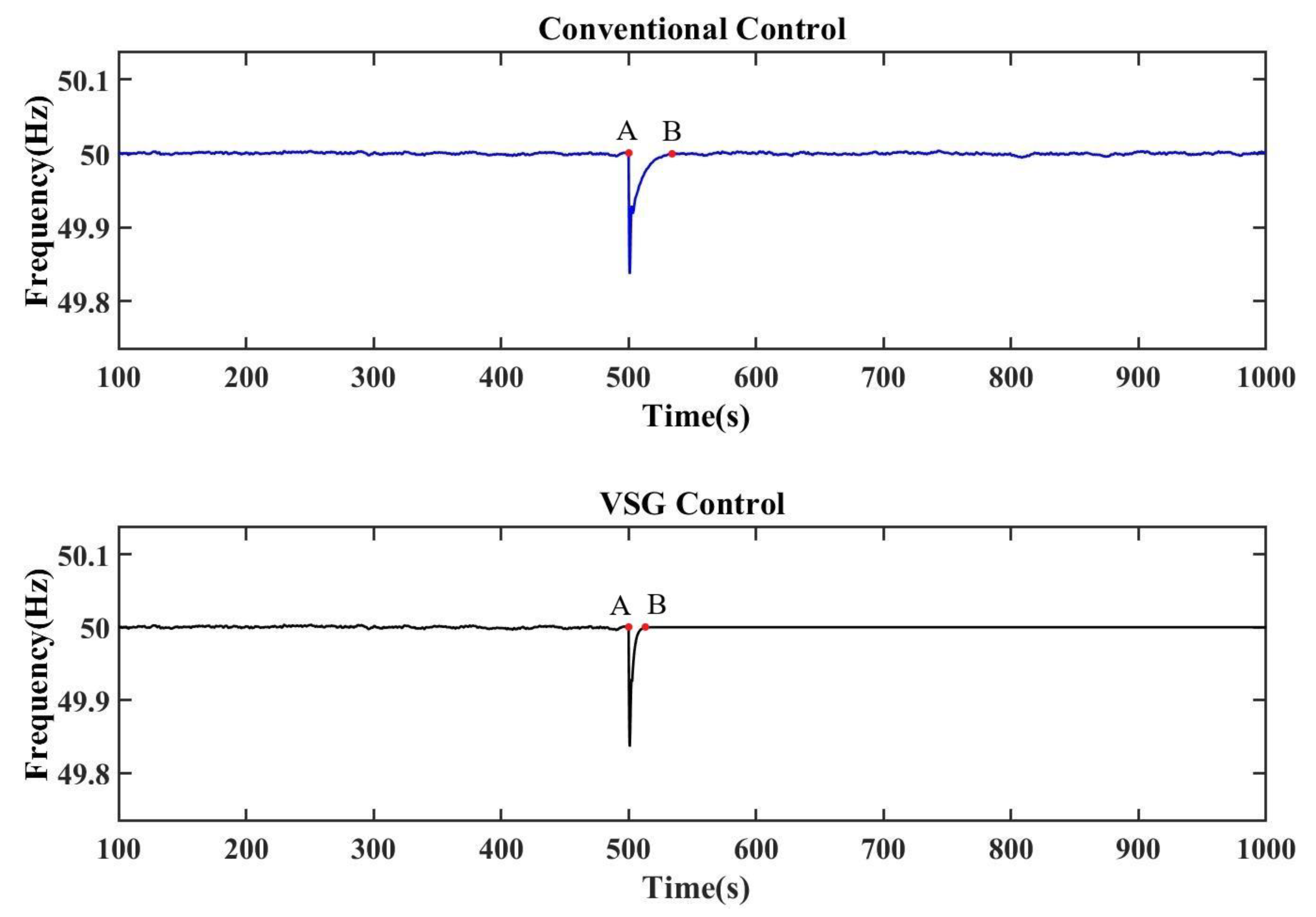
5.1.1. Step Load Test

When t = 500 s, a step load is added to the system to simulate the impact of sudden load or generator unit shutdown on the system. The test results are showed in Figure 8. The traditional control is primary and secondary frequency control, and the VSG control is added with inertia control. When t = 500 s, the system frequency drops due to the sudden increase of load in the system. In the conventional control, the time of frequency change point A and recovery point B is 500 s and 534 s, respectively, which takes a total of 34 s. In VSG control, the time of points A and B is 500 s and 514 s, respectively, which takes a total of 14 s. The control has the advantages of faster frequency recovery and stable frequency and less fluctuation compared with the conventional control.

5.1.2. Random Load Disturbance Test

Figure 9 is a waveform of random load. Figure 10 shows the test results for random load. The random load is connected at t = 500 s to test the ability of the system to deal with random disturbance. The system frequency fluctuates when the random load is connected. In the conventional control, the time of frequency change point A and recovery point B is 500 s and 533 s, respectively, which takes a total of 33 s. In VSG control, the time of points A and B is 500 s and 506 s respectively, which takes a total of 6 s. Compared with conventional control, the system frequency recovery is faster and more stable when VSG control.

5.2. Evaluation of System Performance in Low Inertia Environment

The same test is to test the control effect of the frequency control method in the environment of low system inertia. The test is also carried out under step load and random load. The test results and analysis are as follows.

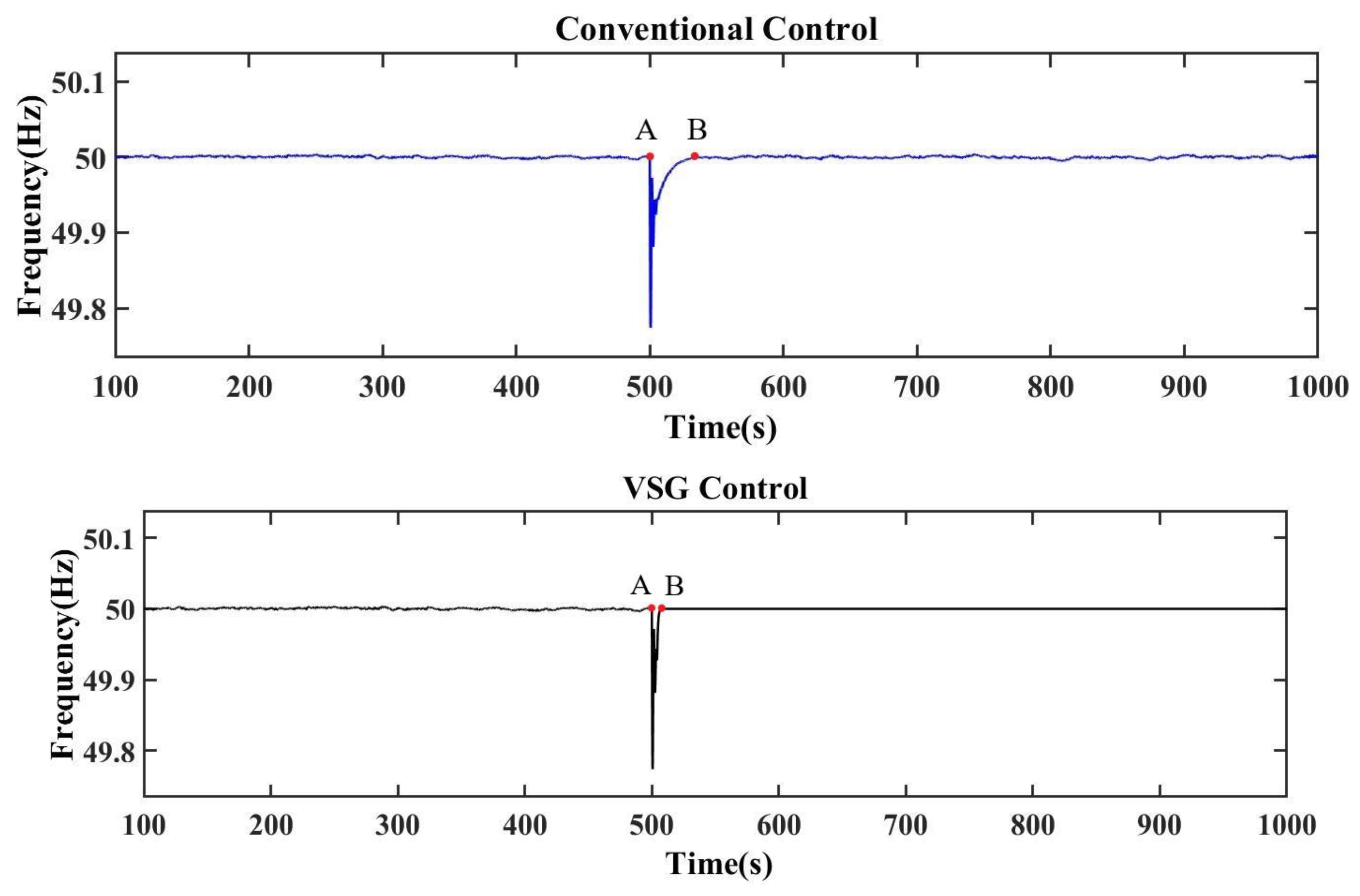
5.2.1. Step Load Test

At t = 500 s, step load is added to the system, and the experimental results are shown in Figure 11. The frequency offset increases under the same load disturbance due to the decrease of system inertia, and the frequency drop increases from 0.15 Hz under high inertia to 0.2 Hz. In the conventional control, the time of frequency change point A and recovery point B is 500 s and 534 s, respectively, which takes a total of 34 s. In VSG control, the time of points A and B is 500 s and 508 s, respectively, which takes a total of 8 s. The VSG control system frequency recovery time is shorter than that of traditional control, and the frequency is more stable.

5.2.2. Random Load Disturbance Test

When t = 500 s, the random load is added to the system, and the experimental results are shown in Figure 12. The frequency is decreased under the disturbance of the same load compared with that of the high inertia. As the system inertia decreases, the frequency deviation increases under the same disturbance. However, in the conventional control, the time of frequency change point A and recovery point B is 500 s and 531 s, respectively, which takes a total of 31 s. In VSG control, the time of points A and B is 500 s and 509 s, respectively, which takes a total of 9 s. VSG control system frequency recovery time is shorter and frequency is more stable compared with the traditional frequency control system.
In summary, step load and random load are added to the system, and carry the experiments under different inertial conditions to prove the adaptability of the control algorithm. VSG control system has shorter frequency recovery time and stronger frequency stability compared with the traditional control, no matter the high system inertia, low system inertia, time step load change, or random load change, which verifies the effectiveness and adaptability of the algorithm proposed. The reason is that VSG enhances the inertia of the system, and the VSG optimized by algorithm enhances the adaptability to the environment, thus restraining the large fluctuation of frequency.

5.3. Egyptian Power System Test

The frequency control scheme proposed is compared with the results of the conventional frequency control schemes to verify the superiority of the scheme. Step load and random load are tested in the test, and the test results prove the adaptability of the scheme. The tests are described in detail below.

5.3.1. Step Load Test

In the Egyptian power system model mentioned, step load is added when t = 500 s and the load value is 0.05 pu to test the system’s ability to cope with step load and system stability. The test results are showed in Figure 13. The first figure is the result of traditional frequency control, the second figure is the result of inertial control strategy proposed.
The system is connected to step load at t = 500 s, the frequency of both control schemes decreases. However, it is obvious that the frequency control scheme proposed to reduce the frequency reduction amplitude, frequency recovery time, and the disturbance degree of step load to the system is due to providing certain inertia to the system. In contrast, the traditional control system does not provide inertial support. During the load disturbance, the frequency fluctuation amplitude is large and the time is long, which affects the frequency stability of the system.

5.3.2. Random Load Disturbance Test

When t = 500 s, the system is connected with the random load to simulate the large-scale random load in real life connected to the power system at any time. The random load waveform is shown in Figure 9. The test results are shown in Figure 14.
When t = 500 s, the random load is connected and the system frequency drops. Without inertia control, the drop amplitude reaches 0.004 Hz, the frequency instability time is longer. With inertia control, the frequency drop amplitude is 0.002 Hz, the frequency instability time is shorter, and the steady-state frequency is smoother. The inertia and frequency stability of the system are increased by using the frequency control method proposed in this study. The results verify the effectiveness of the frequency control scheme. The frequency control method proposed is superior to the traditional control method.

6. Conclusions

In RE systems, this study develops a VSG frequency systematic control method to solve the problem of frequency stability of new energy power systems, which becomes a key challenge for large-scale access of new energy to power systems. The control strategy makes the inverter have the characteristics of traditional SG and also includes the primary and secondary frequency regulation mechanisms. The control loop has certain inertia, which increases the ability of a system to suppress frequency fluctuation, thereby increasing the RE power system frequency stability. The unique control loop structure is designed. The parameters of the control strategy are optimized by using the improved WOA. The virtual controller is designed by the optimization results of the algorithm to achieve the best control effect.
Two kinds of test models are established. The small power system verifies the control effect and adaptive performance of frequency coordination strategy under different inertia conditions. The simulation system is established to verify the VSG systematic control method performance in power system based on the data of an Egyptian electric power holding company. The experimental results show that the proposed frequency coordinated control strategy increases the inertia and damping of the system, so the frequency is more stable compared with the traditional frequency control method. Under the same disturbance, the system frequency fluctuation amplitude and time are significantly reduced, which proves the excellent performance of the frequency coordinated control strategy. The systematic control method proposed in this study improves the inertia of the inverter, so as to improve the frequency stability of the system. The main contribution of this study is to propose a novel control strategy, and also to apply the improved WOA to parameter optimization, so as to maximize the performance of the control strategy. This study solves the problems of low inertia and unstable frequency of RE power system, promotes the penetration of clean energy in power system and promotes sustainable development of environment.
The VSG frequency control is studied to ensure the frequency stability and active power balance of the system. The voltage control is not discussed, which is the deficiency of this study. Reactive power balance and voltage stability of a power system occupy the same important position as frequency stability. Future studies might be on VSG voltage control and more optimization methods to this field to further improve the control strategy and maintain the symmetry between the grid connection rate of new energy and the voltage stability of power system.

Author Contributions

Conceptualization, L.L. and H.L.; methodology, L.L. and H.L.; software, L.L., H.L. and H.F.; formal analysis, M.-L.T. and L.L.; data curation, L.L. and H.L.; writing—original draft preparation, L.L., H.L., M.-L.T., H.F. and A.S.C.; writing—review and editing, M.-L.T. and A.S.C. All authors have read and agreed to the published version of the manuscript.

Funding

This research was funded by the key project of Tianjin Natural Science Foundation [Project No. 19JCZDJC32100] and the Natural Science Foundation of Hebei Province of China [Project No. E2018202282].

Conflicts of Interest

The authors declare no conflict of interest.

References

  1. Awad, N.H.; Ali, M.Z.; Mallipeddi, R.; Suganthan, P.N. An efficient Differential Evolution algorithm for stochastic OPF based active–reactive power dispatch problem considering renewable generators. Appl. Soft Comput. J. 2019, 76, 445–458. [Google Scholar] [CrossRef]
  2. Elsisi, M. New design of adaptive model predictive control for energy conversion system with wind torque effect. J. Clean. Prod. 2019, 240. [Google Scholar] [CrossRef]
  3. Mahbub, M.S.; Wagner, M.; Crema, L. Incorporating domain knowledge into the optimization of energy systems. Appl. Soft Comput. J. 2016, 47, 483–493. [Google Scholar] [CrossRef]
  4. Preda, S.; Oprea, S.-V.; Bâra, A.; Belciu (Velicanu), A. PV forecasting using support vector machine learning in a big data analytics context. Symmetry 2018, 10, 748. [Google Scholar] [CrossRef] [Green Version]
  5. Karasoy, A.; Akcay, S. Effects of renewable energy consumption and trade on environmental pollution. Manag. Environ. Qual. Int. J. 2019, 30, 437–455. [Google Scholar] [CrossRef]
  6. Anastasiadis, A.; Kondylis, G. Hydrothermal coordination in power systems with large-scale integration of renewable energy sources. Manag. Environ. Qual. Int. J. 2016, 27, 246–258. [Google Scholar] [CrossRef]
  7. Shankar, R.; Srinivas, T. Investigation on aqua-ammonia based solar cooling cogeneration plant. Manag. Environ. Qual. Int. J. 2016, 27, 36–44. [Google Scholar] [CrossRef]
  8. Stritih, U.; Paksoy, H.; Turgut, B.; Osterman, E.; Evliya, H.; Butala, V. Sustainable energy management: Solar energy and thermal storage technologies in two Mediterranean countries. Manag. Environ. Qual. Int. J. 2015, 26, 764–790. [Google Scholar] [CrossRef] [Green Version]
  9. Gholami, K.; Dehnavi, E. A modified particle swarm optimization algorithm for scheduling renewable generation in a micro-grid under load uncertainty. Appl. Soft Comput. J. 2019, 78, 496–514. [Google Scholar] [CrossRef]
  10. Selim, A.; Kamel, S.; Jurado, F. Efficient optimization technique for multiple DG allocation in distribution networks. Appl. Soft Comput. J. 2019. [Google Scholar] [CrossRef]
  11. Yao, Y.; Ye, L.; Qu, X.; Lu, P.; Zhao, Y.; Wang, W.; Fan, Y.; Dong, L. Coupled model and optimal operation analysis of power hub formulti-heterogeneous energy generation power system. J. Clean. Prod. 2019. [Google Scholar] [CrossRef]
  12. Ogbonnaya, C.; Turan, A.; Abeykoon, C. Novel thermodynamic efficiency indices for choosing an optimal location for large-scale photovoltaic power generation. J. Clean. Prod. 2019. [Google Scholar] [CrossRef]
  13. Teimourzadeh, S.; Aminifar, F.; Davarpanah, M. Micro-grid dynamic security: Challenges, solutions and key considerations. Electr. J. 2017, 30, 43–51. [Google Scholar] [CrossRef]
  14. Teimourzadeh, S.; Aminifar, F.; Davarpanah, M.; Shahidehpour, M. Adaptive control of micro-grid security. IEEE Trans. Smart Grid 2018, 9, 3909–3910. [Google Scholar] [CrossRef]
  15. Tabar, V.S.; Jirdehi, M.A.; Hemmati, R. Sustainable planning of hybrid micro-grid towards minimizing environmental pollution, operational cost and frequency fluctuations. J. Clean. Prod. 2018, 203, 1187–1200. [Google Scholar] [CrossRef]
  16. Shi, K.; Song, W.; Xu, P.; Liu, R.; Fang, Z.; Ji, Y. Low-voltage ride-through control strategy for a virtual synchronous generator based on smooth switching. IEEE Access 2017, 6, 2703–2711. [Google Scholar] [CrossRef]
  17. Shi, K.; Ye, H.; Song, W.; Zhou, G. Virtual inertia control strategy in micro-grid based on virtual synchronous generator technology. IEEE Access 2018, 6, 27949–27957. [Google Scholar] [CrossRef]
  18. Sedighizadeh, M.; Esmaili, M.; Mousavi-Taghiabadi, S.M. Optimal energy and reserve scheduling for power systems considering frequency dynamics, energy storage systems and wind turbines. J. Clean. Prod. 2019, 228, 314–358. [Google Scholar] [CrossRef]
  19. Gandhi, P.R.; Joshi, S.K. Smart control techniques for design of TCSC and PSS for stability enhancement of dynamical power system. Appl. Soft Comput. J. 2014, 24, 654–668. [Google Scholar] [CrossRef]
  20. Hao, X.H.; Wang, H.M.; Peng, B.; Yao, Z.; Wang, Y.X.; Gu, M.F. Research on the virtual synchronous generator control strategy of grid-connected permanent-magnet direct-driven wind power system. Therm. Sci. 2018, 22, S401–S408. [Google Scholar] [CrossRef]
  21. Hirase, Y.; Abe, K.; Sugimoto, K.; Sakimoto, K.; Bevrani, H.; Ise, T. A novel control approach for virtual synchronous generators to suppress frequency and voltage fluctuations in micro-grids. Appl. Energy 2018, 210. [Google Scholar] [CrossRef]
  22. Navid, N.; Masoud, B.S. Implementing virtual synchronous generator to load-frequency control with penetration of wind turbine considering limitation of storage system capacity. In Proceedings of the 26th Iranian Conference on Electrical Engineering, Mashhad, Iran, 8–10 May 2018; pp. 1280–1285. [Google Scholar] [CrossRef]
  23. Rakhshani, E.; Remon, D.; Mir Cantarellas, A.; Rodriguez, P. Analysis of derivative control based virtual inertia in multi-area high-voltage direct current interconnected power systems. IET Gener. Transm. Distrib. 2016, 10, 1458–1469. [Google Scholar] [CrossRef] [Green Version]
  24. Wang, D.; Zhang, B.; Qiu, D.; Xie, F. On the Super-Lorenz Chaotic Model for the Virtual Synchronous Generator. IEEE Trans. Circuits Syst. II Express Br. 2018, 65, 511–515. [Google Scholar] [CrossRef]
  25. Bao, G.Q.; Tan, H.T.; Ding, K.; Ma, M.; Wang, N.B. A novel photovoltaic virtual synchronous generator control technology without energy storage systems. Energies 2019, 12, 2240. [Google Scholar] [CrossRef] [Green Version]
  26. Yan, X.; Li, J.; Wang, L.; Zhao, S.; Li, T.; Lv, Z.; Wu, M. Adaptive-MPPT-based control of improved photovoltaic virtual synchronous generators. Energies 2018, 11, 1834. [Google Scholar] [CrossRef] [Green Version]
  27. Wu, W.-W.; Lee, Y.-T.; Tseng, M.-L.; Chiang, Y.-H. Data mining for exploring hidden patterns between KM and its performance. Knowl. Based Syst. 2010, 23, 397–401. [Google Scholar] [CrossRef]
  28. Zheng, T.; Chen, L.; Guo, Y.; Mei, S. Flexible unbalanced control with peak current limitation for virtual synchronous generator under voltage sags. J. Mod. Power Syst. Clean Energy 2018, 6, 61–72. [Google Scholar] [CrossRef] [Green Version]
  29. Zhao, F.; Zeng, G.Q.; Lu, K.D. EnLSTM-WPEO: Short-term traffic flow prediction by ensemble LSTM, NNCT weight integration, and population extremal optimization. IEEE Trans. Veh. Technol. 2020, 69, 101–113. [Google Scholar] [CrossRef]
  30. Zeng, G.Q.; Xie, X.Q.; Chen, M.R.; Weng, J. Adaptive population extremal optimization-based PID neural network for multivariable nonlinear control systems. Swarm Evol. Comput. 2019, 44, 320–334. [Google Scholar] [CrossRef]
  31. Jeng, S.-Y.; Lin, C.W.; Tseng, M.; Jantarakolica, T. Cradle-to-cradle zero discharge production planning system for the pulp and paper industry using a fuzzy hybrid optimization model. Manag. Environ. Qual. Int. J. 2020, 31, 3, 645–663. [Google Scholar] [CrossRef]
  32. Magdy, G.; Mohamed, E.A.; Shabib, G.; Elbaset, A.A.; Mitani, Y. SMES based a new PID controller for frequency stability of a real hybrid power system considering high wind power penetration. IET Renew. Power Gener. 2018, 12, 1304–1313. [Google Scholar] [CrossRef]
  33. Li, X.; Chen, G.Z.; Ali, M.S. Improved virtual synchronous generator with transient damping link and its seamless transfer control for cascaded H-bridge multilevel converter-based energy storage system. IET Electr. Power Appl. 2019, 13, 1535–1543. [Google Scholar] [CrossRef]
  34. Chen, J.R.; O’Donnelll, T. Analysis of virtual synchronous generator control and its response based on transfer functions. IET Power Electron. 2019, 12, 2965–2977. [Google Scholar] [CrossRef]
  35. Shuai, Z.; Shen, C.; Liu, X.; Li, Z.; John Shen, Z. Transient angle stability of virtual synchronous generators using lyapunov’s direct method. IEEE Trans. Smart Grid 2019, 10, 4648–4661. [Google Scholar] [CrossRef]
  36. Zhao, L.; Zhou, X. Forecasting electricity demand using a new grey prediction model with smoothness operator. Symmetry 2018, 10, 693. [Google Scholar] [CrossRef] [Green Version]
  37. Du, W.; Fu, Q.; Wang, H.F. power system small-signal angular stability affected by virtual synchronous generators. IEEE Trans. Power Syst. 2019, 34, 3209–3219. [Google Scholar] [CrossRef]
  38. Shi, R.L.; Zhang, X.; Hu, C.; Xu, H.Z.; Gu, J.; Cao, W. Self-tuning virtual synchronous generator control for improving frequency stability in autonomous photovoltaic-diesel micro-grids. J. Mod. Power Syst. Clean Energy 2018, 6, 482–494. [Google Scholar] [CrossRef] [Green Version]
  39. Magdy, G.; Shabib, G.; Elbaset, A.A.; Mitani, Y. Renewable power systems dynamic security using a new coordination of frequency control strategy based on virtual synchronous generator and digital frequency protection. Electr. Power Energy Syst. 2019, 109, 351–368. [Google Scholar] [CrossRef]
  40. Hu, P.; Chen, H.K.; Cao, K.; Hu, Y.C.; Kai, D.; Chen, L.; Wang, Y. Coordinated control of multiple virtual synchronous generators in mitigating power oscillation. Energies 2018, 11, 2788. [Google Scholar] [CrossRef] [Green Version]
  41. Ding, X.Y.; Lan, T.X.; Dong, H.N. Control strategy and stability analysis of virtual synchronous generators combined with photovoltaic dynamic characteristics. J. Power Electron. 2019, 19, 1270–1277. [Google Scholar] [CrossRef]
  42. Zhang, Y.Y.; Zhu, J.Z.; Dong, X.Y.; Zhao, P.C.; Ge, P.; Zhang, X.L. A control strategy for smooth power tracking of a grid-connected virtual synchronous generator based on linear active disturbance rejection control. Energies 2019, 12, 3024. [Google Scholar] [CrossRef] [Green Version]
  43. Wang, X.; Sun, D. Multi-objective self-synchronised virtual synchronous generator in unbalanced power grid. Electron. Lett. 2018, 54, 779–781. [Google Scholar] [CrossRef]
  44. Shi, K.; Zhou, G.; Xu, P.; Ye, H.; Tan, F. The integrated switching control strategy for grid-connected and islanding operation of micro-grid inverters based on a virtual synchronous generator. Energies 2018, 11, 1544. [Google Scholar] [CrossRef] [Green Version]
  45. Fang, J.Y.; Tang, Y.; Li, H.C.; Li, X.Q. A battery/ultracapacitor hybrid energy storage system for implementing the power management of virtual synchronous generators. IEEE Trans. Power Electron. 2018, 33, 2820–2824. [Google Scholar] [CrossRef]
  46. Asrari, A.; Mustafa, M.; Ansari, M.; Khazaei, J. Impedance analysis of virtual synchronous generator-based vector controlled converters for weak AC grid integration. IEEE Trans. Sustain. Energy 2019, 10, 1481–1490. [Google Scholar] [CrossRef]
  47. Zheng, X.M.; Wang, C.; Pang, S.N. Injecting positive-sequence current virtual synchronous generator control under unbalanced grid. IET Renew. Power Gener. 2019, 13, 165–170. [Google Scholar] [CrossRef]
  48. Zeng, H.H.; Su, H.S. Self-adaptive control of rotor inertia for virtual synchronous generator in an isolated micro-grid. J. Phys. Conf. Ser. 1187 2019, 022007. [Google Scholar] [CrossRef]
  49. Liu, J.; Miura, Y.; Ise, T. Fixed-parameter damping methods of virtual synchronous generator control Using State feedback. IEEE Access 2019, 7, 99177–99190. [Google Scholar] [CrossRef]
  50. Cao, Y.J.; Wang, W.Y.; Li, Y.; Tan, Y.; Chen, C.; He, L.; Hager, U.; Rehtanz, C. A Virtual Synchronous Generator Control Strategy for VSC-MTDC Systems. IEEE Trans. Energy Convers. 2018, 33, 750–761. [Google Scholar] [CrossRef]
  51. Yu, Y.J.; Hu, X.Y. Active disturbance rejection control strategy for grid-connected photovoltaic inverter based on virtual synchronous generator. IEEE Access 2019, 7, 17328–17336. [Google Scholar] [CrossRef]
  52. Chen, M.R.; Zeng, G.Q.; Xie, X.Q. Population extremal optimization-based extended distributed model predictive load frequency control of multi-area interconnected power systems. J. Frankl. Inst. 2018, 355, 8266–8295. [Google Scholar] [CrossRef]
  53. Lu, K.; Zhou, W.; Zeng, G.; Zheng, Y. Constrained population extremal optimization-based robust load frequency control of multi-area interconnected power system. Int. J. Electr. Power Energy Syst. 2019, 105, 249–271. [Google Scholar] [CrossRef]
  54. Mirjalili, S.; Lewis, A. The Whale Optimization Algorithm. Adv. Eng. Softw. 2016, 95, 51–67. [Google Scholar] [CrossRef]
  55. MEHC. Annual Report of Egypt Electricity 2016/2017; Egyptian Electricity Holding Company: Cairo Governorate, Egypt, 2018. [Google Scholar]
Figure 1. Virtual controller structure.
Symmetry 12 01697 g001
Figure 2. Results of running test functions.
Symmetry 12 01697 g002aSymmetry 12 01697 g002b
Figure 3. Wind power model.
Symmetry 12 01697 g003
Figure 4. Photovoltaic model.
Symmetry 12 01697 g004
Figure 5. Load model.
Symmetry 12 01697 g005
Figure 6. Micro-grid system model.
Symmetry 12 01697 g006
Figure 7. Egyptian power system model.
Symmetry 12 01697 g007
Figure 8. Comparison of load sudden change control effect.
Symmetry 12 01697 g008
Figure 9. Random load power diagram.
Symmetry 12 01697 g009
Figure 10. Effect comparison of random load control.
Symmetry 12 01697 g010
Figure 11. Comparison of step load control effect.
Symmetry 12 01697 g011
Figure 12. Effect comparison of random load control.
Symmetry 12 01697 g012
Figure 13. Step load test diagram.
Symmetry 12 01697 g013
Figure 14. Simulation diagram of random load disturbance.
Symmetry 12 01697 g014
Table 1. Wind power plant parameters.
ParameterValueParameterValue
V w i n d 12 B 4 5
ρ 1.23 B 5 21
A 5905 B 6 0.02
B 1 0.39 r T 43.36
B 2 116 n T 22.50
B 3 0.40
Table 2. Micro-grid parameters.
ParameterValueParameterValue
K 1 0.42 H ν 0.92
K 2 0.05 D ν 10.50
T 1 0.10 H i 0.05
T 2 0.42 S a t u r a t i o n 1 0.05
T s 0.082 S a t u r a t i o n 2 0.02
D s 0.015 R ate   L i m i t 0.20
Table 3. Whale optimization algorithm (WOA) parameter settings.
ParameterSearch Agent NumberMaximum IterationsProbability Coefficient
Value30100.50
Table 4. Controller parameters.
ParameterK1K2K3
Value385277
Table 5. Egyptian power system parameters.
ParameterValueParameterValueParameterValue
H s 5.71 T w 1 P 3 0.14
D s 0.03 m 0.50 K p 71.25
H s T 1 0.40 R 1 2.50 K i 5.91
T 2 0.40 R 2 2.50 K d 6.10
T 3 90 R 3 1 H ν 0.90
T d 5 P 1 0.25 D ν 10.40
T h 6 P 2 0.61 T i 0.04
Table 6. Optimal parameters.
ParameterK1K2K3
Value234156
Publisher’s Note: MDPI stays neutral with regard to jurisdictional claims in published maps and institutional affiliations.

