Article

Study of the Vibration-Energy Properties of the CRTS-III Track Based on the Power Flow Method

School of Civil Engineering, Beijing Jiaotong University, Beijing 100044, China
*
Author to whom correspondence should be addressed.
Symmetry 2020, 12(1), 69; https://doi.org/10.3390/sym12010069
Submission received: 9 December 2019 / Revised: 26 December 2019 / Accepted: 29 December 2019 / Published: 1 January 2020

Abstract

:
The vibration induced by the high-speed railway (HSR) system has been a severe problem during the construction and operation period. To investigate the vibration-energy properties of the China Railways Track System (CRTS)-III track, a vehicle-track-subgrade coupling model is developed, in which the distribution of the tangent force is symmetrical according to the FASTSIM theory, and the power flow method is utilized. What’s more, the corresponding evaluation indexes of the power flow are proposed to analyze the vibration energy of the track structure. The results reveal that the vibration energy decreases from top to bottom of the track structure among the frequency considered, and the decreasing trend is obvious. The vibration energy of the track structure is sensitive to the stiffness of fasteners. Differently, the vibration energy of the composite slab and the base slab is more sensitive to the stiffness of rubber damping pads than that of the rail. To sum up, this paper can provide a new perspective and method to study the vibration-energy properties and select the reasonable stiffness of the fasteners and the rubber damping pads of the CRTS-III track, and the proposed values of the stiffness of the fasteners and the rubber damping pads for the case under this study are 40 kN/mm and 400 MPa/m, respectively.

1. Introduction

The vibration induced in the railway system has still been a crucial problem during the construction and operation period, which has drawn a lot of attentions from scholars and researchers. Tang et al. [1] developed a finite element (FE) model to investigate the vibration behaviors of embankment induced by high-speed train in seasonally frozen regions and the model was validated by the field test. Further, the results convincingly indicated that the vibration mitigation effect of the wave impeding barrier (WIB) would be improved when its modulus and size increased or the embedded depth decreased. Rådeström et al. [2] established a single-degree-of-freedom model to investigate the possibility of reducing the acceleration of one of these bridges to an acceptable level by using post-installed viscous dampers. Moreover, the results indicated that the proposed retrofit method can reduce the accelerations to an acceptable level. Ferreira and López-Pita [3] built a numerical model to correctly predict train/track dynamic response not only instantaneously but also in a long-term perspective. In addition, the results were evaluated in the perspective of track vibrations mitigation and track maintenance needs. Olivier et al. [4] developed an FE model to investigate the effect of embankment stiffness on ground vibration levels both within and at distance from the track-embankment structure, and it is found that ground vibration levels are sensitive to embankment stiffness, with stiffer embankments resulting in greatly reduced vibration levels.
The vibration and noise induced in China high-speed railway (HSR) system have already raised concerns because plenty of complaints about these problems have been received by the relevant department from the residents along the railways, some institution using the high accuracy instruments, schools, hospitals, etc. The ballastless track system has been widely employed in China HSR system to reduce vibration and noise, which is named China Railways Track System (CRTS). The CRTS-III track has been widely adopted in many HSR lines, such as Zhengzhou–Xuzhou HSR line, Beijing–Shenyang HSR line, Shangqiu–Hangzhou HSR line [5], and so on. In addition, the CRTS-III track has been exported overseas so far. Further, the CRTS-III track consists of rails, the fasteners system, the track slab, the self-compacting concrete, the rubber damping pad, the base slab, and so on [6].
To solve the problems of the ambient vibration and noise induced by the HSR system in China, a large number of researches have been conducted on the CRTS-III track. The rubber damping pad connects the self-compacting concrete with the base slab, and it can effectively absorb the vibration and reduce the noise. The rubber damping pad has been studied for many years in China. Xin and Gao [7] established a vehicle-track-bridge coupling system dynamics model to investigate the effectiveness of elastic materials in vibration reducing. The results demonstrated that elastic materials like slab mat layer inserted between slab track and bridge can reduce vibration transmitted from track into the bridge. Zhao and Wang [8] studied the damping effect of rubber absorbers for ballastless track on viaduct by field test. Moreover, the results showed that after laying rubber absorbers, the vibrations of rails and track slabs above rubber absorbers have been slightly enlarged, but the impact is very little. Ren et al. [9] developed a two-dimension CRTS-III track model in frequency domain to study its vibration transmission and vibration isolation performance. In addition, some recommended slab track parameters were put forward based on the numerical simulation to improve the vibration isolation efficiency. Xin et al. [10] established the dynamic analysis model for high-speed train and CRTS-Ⅲ track coupled system to conduct the analysis of the dynamic effects and the structure optimization of damping layers of CRTS-Ⅲ track. Zhao and Wang [11] evaluated and analyzed the effects of the rubber mats on noise and vibration of the vehicle, the track system, the bridge, and so on based on the field experiment in one China HSR line.
So far, many researches have made contributions to reduce the ambient vibration induced by the track structure, but these researches ignore the energy redistribution due to the application of rubber damping pads. In order to study the energy properties of the track structure, the energy method needs to be applied. Further, the power flow method based on the vibration isolation theory has been widely used to investigate the vibration energy of the vibration isolation system, besides the power-flow indexes have been taken as the vibration evaluation standard. At present, the power flow method has been widely employed in the areas of mechanical engineering, marine engineering, aerospace engineering, etc. Goyder and white [12,13,14] proposed the concept of the vibrational power flow and applied it to study the vibration of built-up structures in 1980. From that on, many power flow methods have made progress, and among those, the mobility power flow, due to the characteristics of the clear concept, simple calculation, and the applicability of studying at low and medium frequency, has been one of the most extensively used methods of the vibration researches. Petersson and Plunt [15] first put forward the concept of mobility, the theoretical background, and basic experimental studies, which provided the theoretical basis on the application of the mobility power flow method in practical engineering. Hussein and Hunt [16] developed a new method based on calculating the mean power flow to evaluate the performance of vibration countermeasures for underground tunnels of underground railways in the wavenumber-frequency domain. Li and Wu [17] presented a general procedure based on the force method to obtain the power flow within a coupled vehicle–track–bridge system in urban rail transit systems, the point mobility of the system, and the dynamic interaction forces connecting various components.
To sum up, few researches have been conducted on the vibration-energy properties of the track structure in the HSR system. Therefore, in this paper, the mobility power flow method is employed to investigate the vibration-energy properties of the track structure in the HSR system, which is taken the CRTS-III track as the research objective. A fine spatial coupling dynamic model of the vehicle, the track system, and the subgrade is established in this paper. The influences of the stiffness of fasteners and the rubber damping pads on the vibration energy of the track structure are analyzed. This paper is of great importance to understand the vibration of the HSR track structure from the perspective of energy systematically and provides the theoretical basis on the mechanism of the vertical energy transfer of the track structure. Furthermore, this method can be also employed to study the vibration-energy properties of other type track structures in the HSR system.

2. Model Description

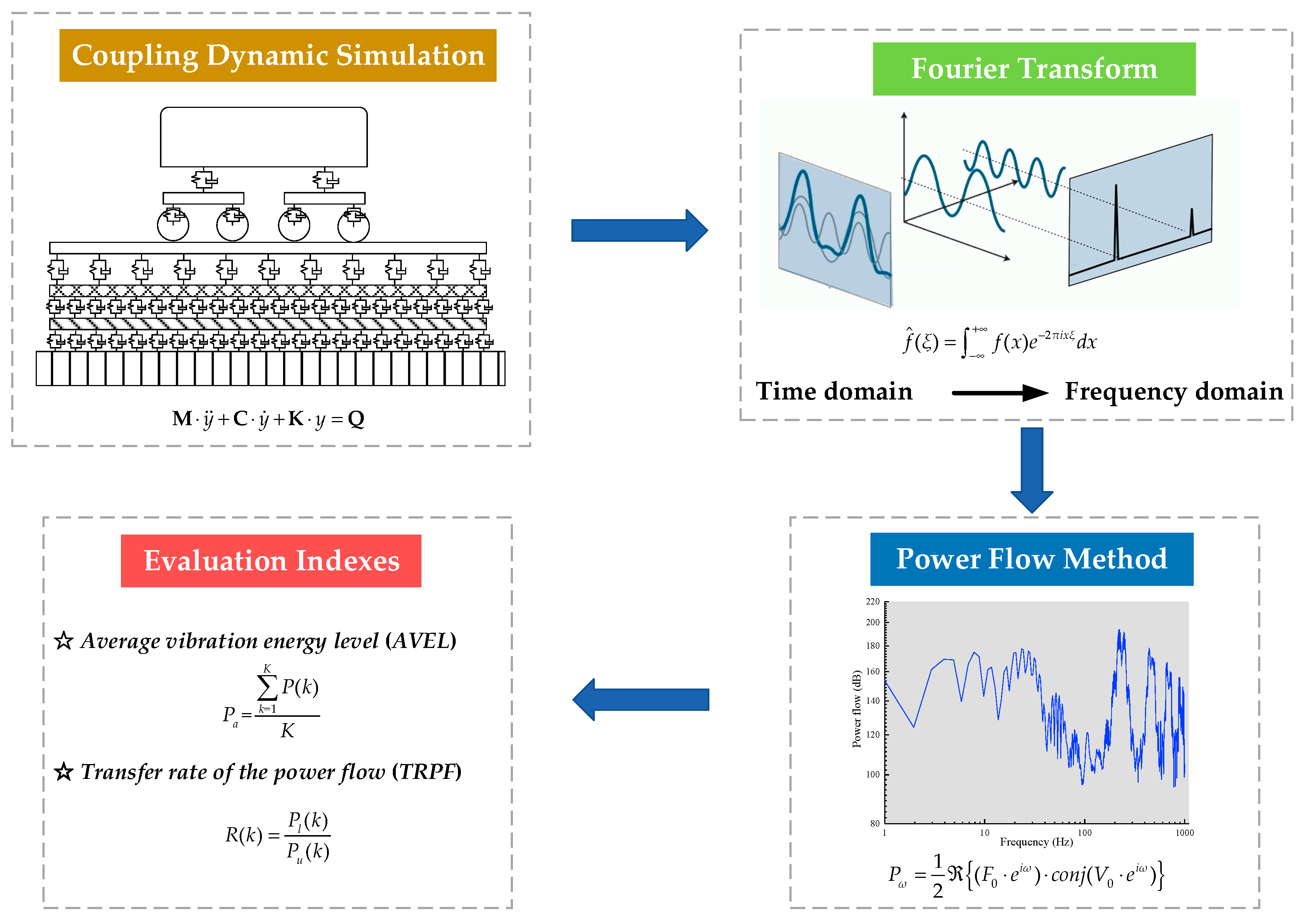
In this section, the vehicle-track-subgrade coupling dynamic model and power flow method are included. Additionally, the analysis of the vibration-energy properties by the means of MATLAB is illustrated in the flow chart of Figure 1.

2.1. Vehicle Model

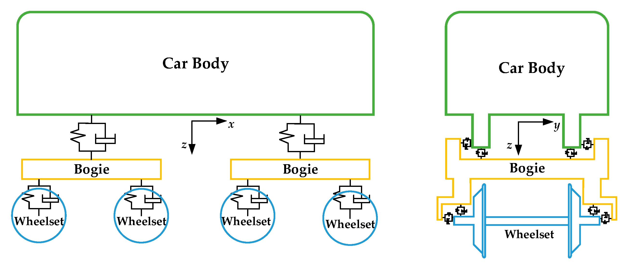
The CRH2 vehicle model is established by the means of the multi-body dynamics, which consists of one car body, two bogies, four wheelsets, and suspension systems, and the components are regarded as rigid bodies. What’s more, the vehicle model, with six degrees of freedom in the car body and bogies, and five degrees of freedom in wheelsets, has 38 degrees of freedom totally. The primary and secondary suspension systems are modeled by nonlinear springs, which take the stiffness and damping in the lateral, vertical, and longitudinal directions into account. The topological graph of the vehicle model is illustrated by Figure 2, in which x, y, and z denote the longitudinal, lateral, and vertical directions, respectively.
The kinematic equation of rigid body systems can be derived from the Newton–Euler method [18], as expressed by Equation (1):
M ( y , t ) y ¨ + k ( y , y ˙ , t ) = q ( y , y ˙ , t ) ,
where M, k, and q denote the mass matrix, the constraint matrix, and the general force matrix, respectively; y, y ˙ , and y ¨ refer to the displacement, the velocity, and the acceleration vector, respectively; t represents time.
The parameters of the CRH2 vehicle model established in this paper are listed in Table 1.

2.2. Track Model

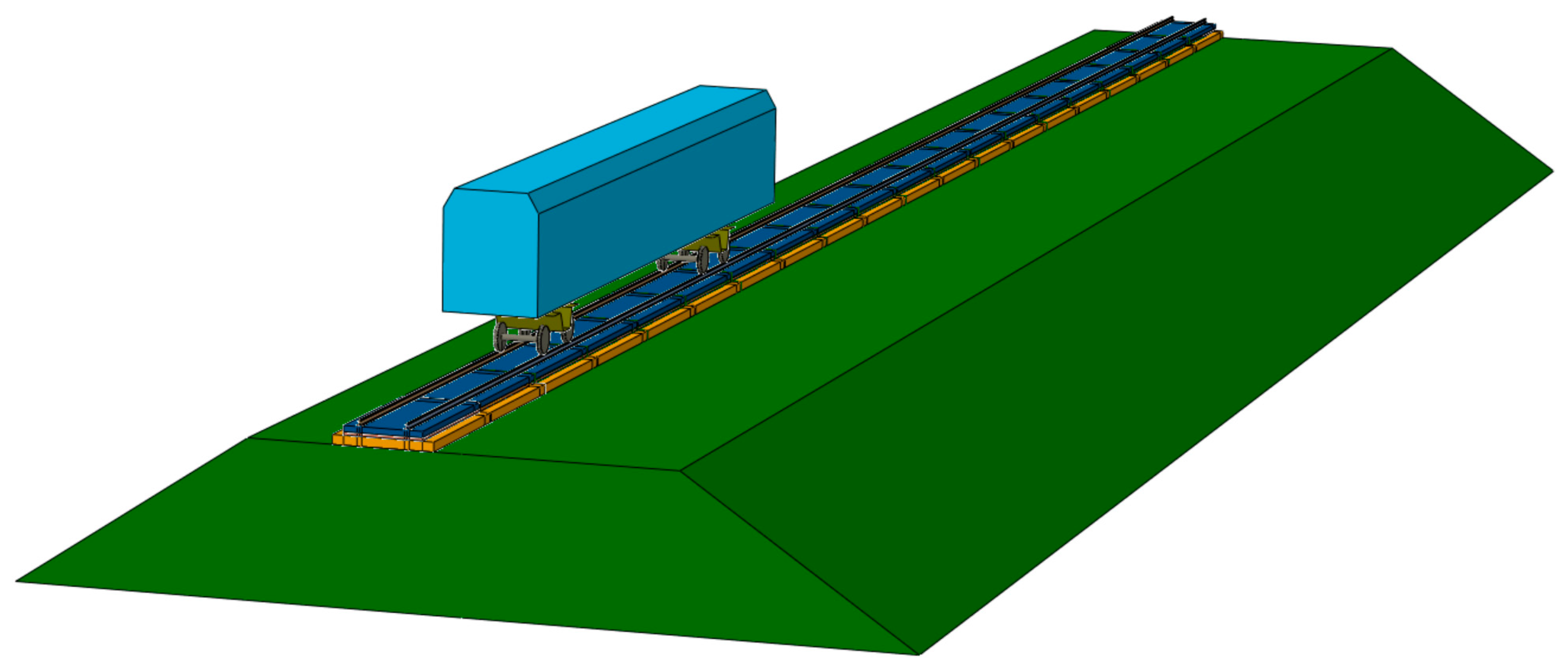
The CRTS-III track model developed in this paper from top to bottom comprises the rails, fasteners, the composite slab (including the slab and the self-compacting layer), rubber damping pads, and base slab, as shown in Figure 3. In addition, the longitudinal deformation of the track model is neglected, and the fasteners connecting rails and the composite slab are modeled by the spring-damper elements, which include lateral and vertical stiffness and damping. The rubber damping pads are modeled by spring-damper elements as well, which only considers the vertical stiffness and damping. Moreover, the rails, slab, self-compacting concrete, base slab, and subgrade are established by solid elements, which can reflect the geometry and physical properties of the track structure more truthfully. The main parameters of the track model developed in this paper are listed in Table 2.
The substructure model is derived by the method from Guyan [19] to reduce the stiffness and mass matrices, as described by Equation (2):
[ M e e M e i M i e M i i ] [ Y ¨ e Y ¨ i ] + [ C e e C e i C i e C i i ] [ Y ˙ e Y ˙ i ] + [ K e e K e i K i e K i i ] [ Y e Y i ] = [ F e F i ] ,
where M, C, K, F represent the mass matrix, damping matrix, stiffness matrix, and the load vector, respectively; Y, Y ˙ , and Y ¨ are the displacement, velocity, and acceleration vector, respectively; e denotes the external degree of freedom that can be reduced; i refers to the interior degree of freedom that can be reduced.
The displacement of the flexible track can be described by a dynamic equation in a fixed reference system, as expressed by Equation (3):
d ( y , t ) = r ( y r ( t ) ) + s ( y , t ) ,
where d ( y , t ) is the displacement of the flexible track; r ( y r ( t ) ) represents the Ritz method expressed by yr(t); s ( y , t ) refers to the small deformation of the flexible track, which can be expressed by Equation (4) in the low mode approximatively.
s ( y , t ) i = 1 I q i ( t ) s i ( y , t ) ,
where qi(t) denotes the vibration type of the elastic body; s i ( y , t ) represents the modality of vibration. And the dynamic responses of the track can be depicted by Equations (3) and (4).

2.3. Wheel/Rail Interaction Model

The interaction between the wheel and the rail is carried out by the wheel/rail contact. Moreover, the wheel/rail contact is divided into the normal contact and the tangent contact.

2.3.1. Normal Contact

The Hertz nonlinear contact theory is adopted to calculate the wheel/rail normal force [20], which is presented by Equation (5):
N = [ Δ Z ( t ) G ] 3 2 ,
where ΔZ(t) refers to the elastic penetration; G is the contact coefficient, and the value is 4.25342 × 10⁻⁸ in this study. Moreover, ΔZ(t) can be expressed by Equation (6):
Δ Z ( t ) = Z w i ( t ) Z r i ( x , t ) ξ ( x ) ,
where Zwi(t) is the vertical displacement of the ith wheel; Zri(x,t) represents the vertical displacement of the one side rail at the corresponding contact position; ξ(x) is the vertical irregularity. It is worth noting that when ΔZ(t) is less than zero, the wheel/rail normal force is regarded as zero.
Based on that, the normal force caused by the wheel/rail elastic compressibility can be obtained at every time step.

2.3.2. Tangent Contact

The FASTSIM theory is applied to calculate the wheel/rail tangent force [21], and the longitudinal creep rate ξx, lateral creep rate ξy, and spin creep rate ξspin utilized in that theory are presented in Equation (7):
{ ξ x = V w 1 V r 1 V ξ y = V w 2 V r 2 V ξ s p i n = Ω w 3 Ω r 3 V ,
where Vw1, Vw2, and Ωw3 are the longitudinal line velocity, the lateral line velocity, and the angular velocity of the wheel at the wheel/rail contact position, respectively; Vr1, Vr2, and Ωr3 refer to the longitudinal line velocity, the lateral line velocity, and the angular velocity of the rail at the wheel/rail contact position, respectively.
According to the FASTSIM theory, it is assumed that the contact region is completely regarded as the adhesion area and the distribution of the tangent force is symmetrical. Therefore, the longitudinal creep force has no relation to the lateral creep rate, and so do the lateral creep force with the longitudinal creep rate. The linear relationships between the creep force and the creep rate are expressed by Equation (8):
{ T x = f 11 ξ x T y = f 22 ξ y f 23 ξ s p i n M z = f 32 ξ y f 33 ξ s p i n ,
where f11 denotes the longitudinal creep coefficient; f22 represents the lateral creep coefficient; f23 and f32 are the lateral/spin creep coefficient; f33 refers to the spin creep coefficient. Furthermore, the creep coefficients can be obtained by Equation (9):
{ f 11 = E a b C 11 f 22 = E a b C 22 f 23 = f 32 = E ( a b ) 2 / 3 C 23 f 33 = E ( a b ) 2 C 33 ,
where a and b are the semi-major axis and semi-minor axis of the ellipse contact patch based on the Hertz nonlinear contact theory; E denotes the elasticity modulus; Cij represents the Kalker coefficient, which can be found in Kalker [21].
Based on these theories mentioned above, a fine vehicle-track-subgrade coupling model is developed, and the model is employed to conduct the analysis of the dynamic responses, which is shown in Figure 4.

2.4. Model Verification

To evaluate the correctness of the model, the simulation results are compared with those obtained by Lou et al. [22]. Further, the comparisons of dynamic responses are listed in Table 3, which are conducted under the same condition, such as the running speed is 250 km/h, the track is the CRTS-III track, irregularities are included, etc., and the details can be found in Lou et al. [22]. It can be observed from Table 3 that the simulated results in this paper are basically the same as those in Lou et al. [22]. Therefore, the model established in this paper can accurately depict the dynamic responses of the vehicle and the track structure.

2.5. Power Flow Method

The power flow method has already been applied in the field of vibrations, but the average power flow is more meaningful in the analysis of vibration. As a result, the frequency-domain average power flow [23] is utilized in this paper, and the mathematical expression is expressed by Equation (10):
P ω = 1 2 { ( F 0 · e i ω ) · c o n j ( V 0 · e i ω ) } ,
where { . } and c o n j ( . ) denote the real part and complex conjugate of a complex number, respectively; F0 and V0 represent the amplitudes of the force and velocity, respectively.
As for the track structure, the process of calculating the power flow is to obtain the time-domain results of nodes’ velocities and spring-damper elements’ forces first, and then the time-domain results are converted into the frequency-domain results by the Fourier transform. What’s more, the time-domain and the frequency-domain results are shown in the figure below, which are taken the nodes in the rail and fasteners as examples (seen in Figure 5). The power flow of the jth node at the frequency of kHz is described by Equation (11):
P j ( k ) = 1 2 { ( F j · e i k ) c o n j ( V j · e i k ) } ,
To depict the influence of the vehicle dynamic behavior on the vibration energy of the track structure, it is needed to sum up the power flow of all nodes in the area of interest. Furthermore, the mathematical expression is expressed as follows:
P ( k ) = 1 2 j = 1 J { ( F j · e i k ) · c o n j ( V j · e i k ) } ,
where J is the number of nodes; k refers to the frequency.
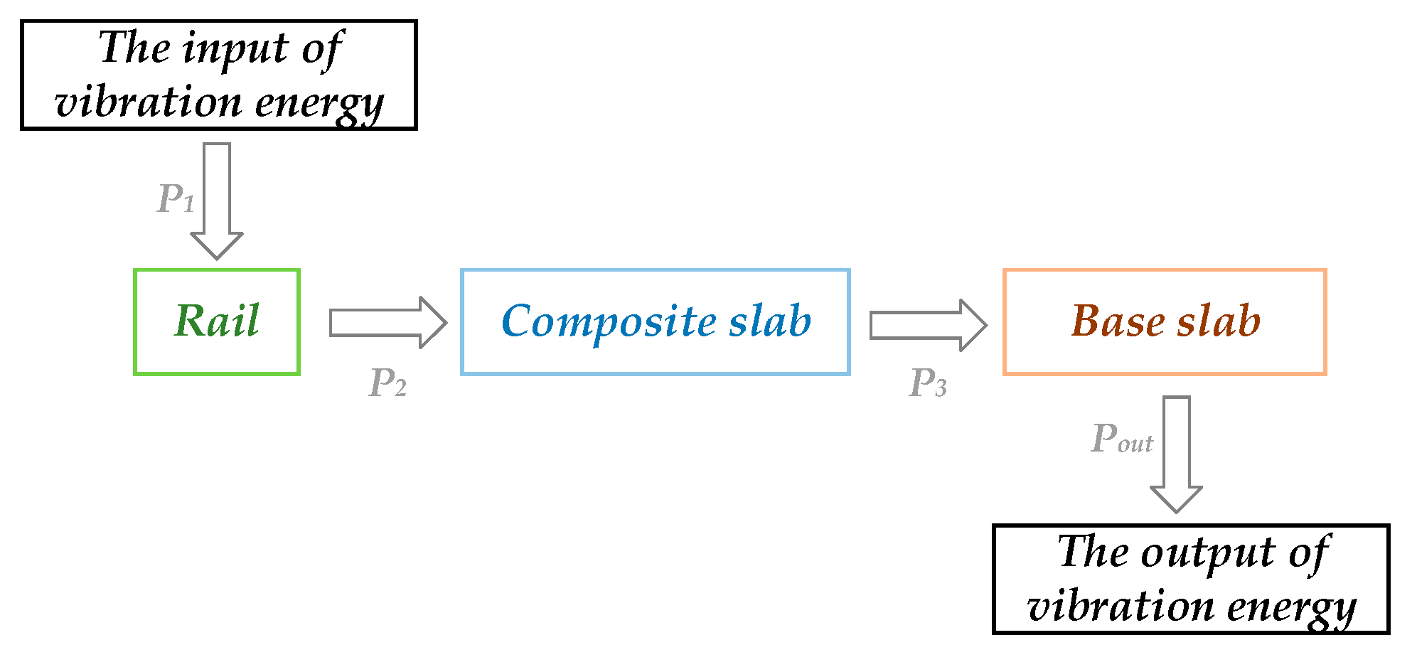
In order to balance the accuracy of the research and the computational efficiency, a proper area of interest needs to be selected. In this paper, the slab in the middle of the subgrade is selected to conduct the research of the power flow. What’s more, the power flow of the rail and the connected nodes of fasteners is summed up as the input power flow of the track structure, which is denoted as P1. The power flow of the composite concrete and the connected nodes of the rubber damping pads is summed up as the input power flow of the composite concrete, which is represented as P2. Moreover, the power flow of the base slab and the connected nodes of the rubber damping pads is summed up as the input power flow of the base slab, which is referred to as P3. Finally, the power flow is transferred from the base slab to the subgrade, which is denoted as Pout. Further, the vertical transfer of the power flow in the track structure is shown in Figure 6.
For the purpose of comparing the power flow obviously, it is necessary to calculate the relative power flow, which is expressed by Equation (13):
P r ( k ) = 20 × lg [ P s ( k ) P 0 ] ,
where Ps(k) is the total power flow; P0 refers to the reference power flow, whose value is set as 1 × 10⁻⁶ N·m/s.

2.6. Evaluationindexes of Vibration Energy

Referring to the present dynamic evaluation indexes of the track in frequency domain, the average vibration energy level (AVEL) and the transfer rate of the power flow (TRPF) are put forward in this section, which describe the vibration energy and its vertical transfer of the track structure on the whole.
The AVEL is defined by Equation (14):
P a = k = 1 K P ( k ) K ,
where Pa is the AVEL of one structure; K refers to the number of the frequency points investigated.
What’s more, the TRPF is expressed by Equation (15):
R ( k ) = P l ( k ) P u ( k ) ,
where Pl(k) represents the power flow of the lower structure connected by spring-damper elements in the track structure; Pu(k) denotes the power flow of the upper structure connected by spring-damper elements in the track structure. The TRPF depicts the rate of the energy transferring from the upper structure to the lower one. Further, the higher the TRPF is, the more energy transfers.

3. Results and Discussion

The power flows and corresponding evaluation indexes of the track structure under irregularities and various stiffness of fasteners and rubber damping pads are calculated, when the vehicle speed is set as 250 km/h.

3.1. Power Flow of the Track Structure under Irregularities

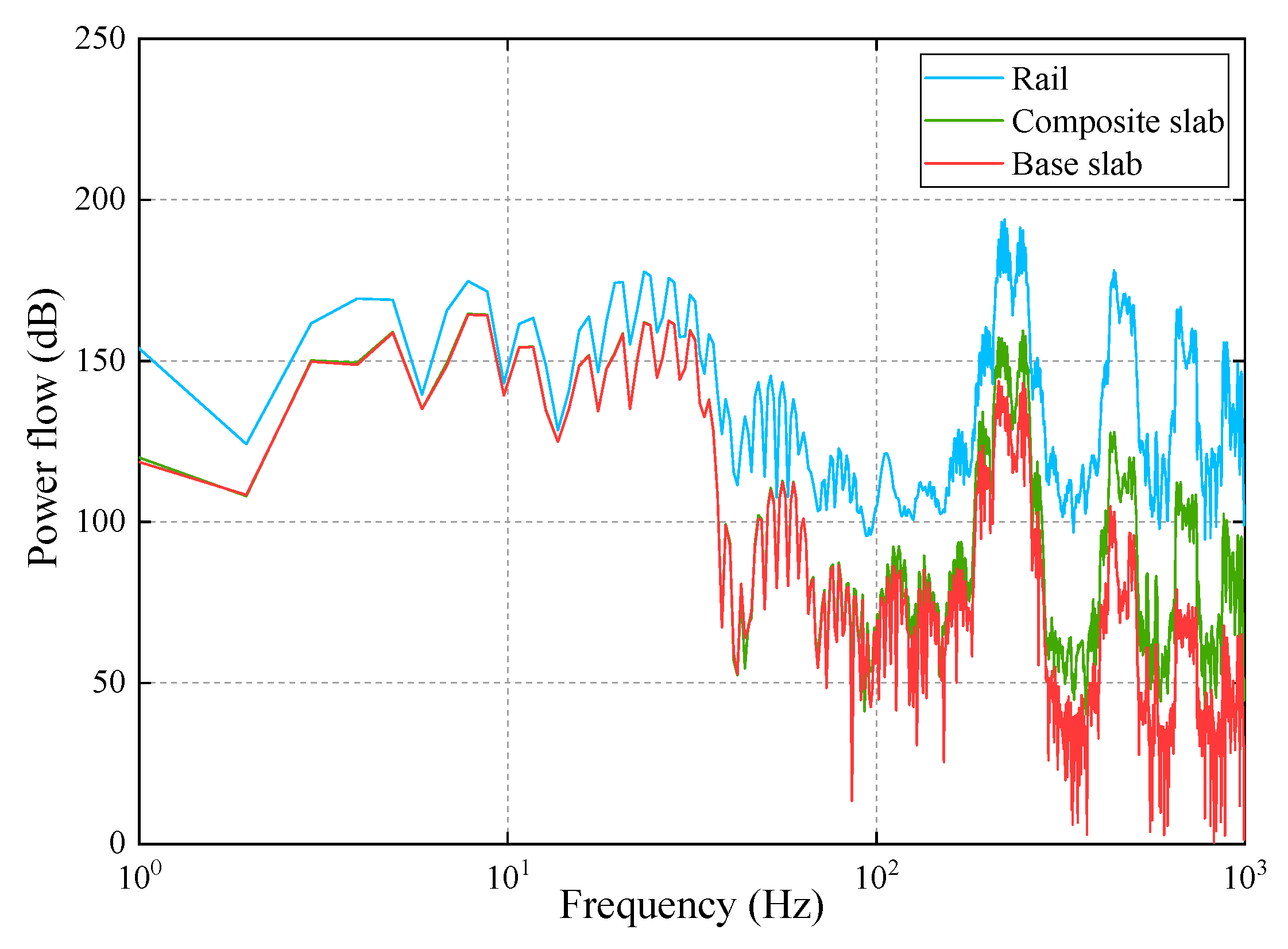
The dynamic responses of the track structure are obtained under the irregularities measured in China HSR, and then the power flow of the track structure is analyzed based on the dynamic responses mentioned above, which is illustrated in Figure 7.
It can be observed from Figure 7 that the power flow of the track structure decreases from top to bottom among the frequency range considered, and the decreasing trend is obvious. This occurrence of decreasing trend is because the vibration energy, which is generated by the interaction of the wheel and the rail, is stored and consumed partly in every structure during the transferring process from top to bottom. In addition, there are many peaks in the power flow of the track structure among the frequency range considered. Furthermore, the peaks of the track structure at the frequencies of 220 Hz and 250 Hz are much bigger, which are related to the vibration characteristics of the track structure and the irregularities. Additionally, the peaks of the track structure at the frequencies of 220 Hz and 250 Hz are much bigger, which are related to the vibration characteristics of the track structure and the irregularities. Because the irregularities employed in our model are sampled at the interval of 0.5 m, so the impact between the rail and wheel is at a certain frequency when the running speed is constant. Besides, the components of the track structure have several resonance frequencies. Therefore, the components of the track structure reach the peaks of the power flow at those frequencies.
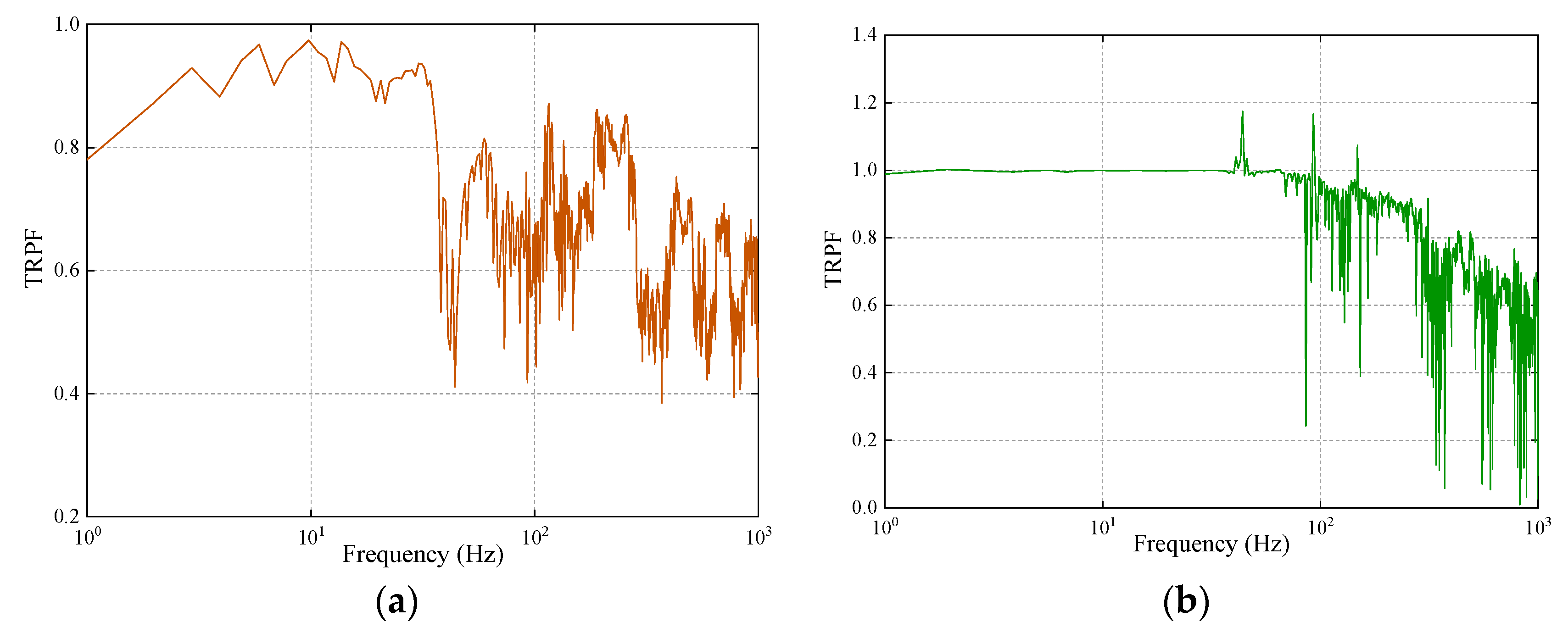
The TRPF of the track structure is shown in Figure 8. Further, it can be seen from Figure 8 that the TRPFs from the rail to the composite slab are always below 1.0, but those from the composite slab to the base slab sometimes exceed 1.0 whereas they are smaller than 1.0 on the whole. The reason why the TRPFs sometimes are larger than 1.0 is that at these frequencies the structure occurs the resonance phenomenon. What’s more, at the frequency ranges of 34 to 44 Hz, 65 to 102 Hz, 115 to 148 Hz, and 264 to 1000 Hz, the TRPFs from the rail to the composite slab tend to decrease, which are caused by the stiffness and damping of fasteners. As a result, the fasteners have a better vibration damping performance at those frequency ranges mentioned above. Besides, the TRPFs from the composite slab to the base slab tend to reduce at the frequency range of 100 to 1000 Hz, which are induced by the stiffness and damping of the rubber damping pads. It can be concluded that the rubber damping pads can achieve an excellent vibration damping effect at the frequency range of 100 to 1000 Hz.
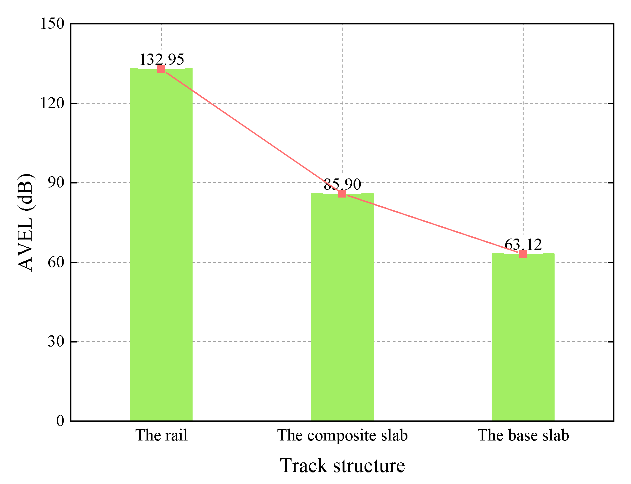
The AVEL of the track structure is demonstrated in Figure 9. It can be seen that similar to the power flow, the AVEL deceases obviously from the top to the bottom of the track structure, which is caused by the energy stored and consumed in every structure as well. Besides, the decrement of the AVEL from the rail to the composite slab is bigger than that from the composite slab and the base slab.

3.2. The Influence of the Stiffness of Fasteners on the Power Flow

To compare and analyze the influence of the stiffness of fasteners, the stiffness is set as 30 kN/mm, 40 kN/mm, 50 kN/mm, and 60 kN/mm, and the power flows, the TRPFs, and the AVELs are calculated.
The power flows of the track structure employing different stiffness of fasteners are illustrated in Figure 10. It can be seen from Figure 10a that the peak values of the rail decrease with the increase of fasteners’ stiffness at the frequency range of 3 to 36 Hz. The differences are seriously obvious when the fastener’s stiffness increases from 30 kN/mm to 40 kN/mm, and the maximum difference can reach to 4.92 dB. When the stiffness of fasteners exceeds 40 kN/mm, the differences of the power flows of the rail are less obvious than those mentioned above. Though the differences of the power flows of the rail are small from 36 to 1000 Hz, it can be noticed that when the stiffness of fasteners is 60 kN/mm the power flows are maximum by and large.
Figure 10b shows that the power flows of the composite slab does not simply change with the increases of fasteners’ stiffness. In the frequency range of 2 to 8 Hz, the power flows, when using the fasteners with stiffness of 40 kN/mm, are distinctly the minimum. Due to the track structure consisting of many components, the vibrations are interactional. Therefore, when employing certain stiffness, the power flows may be the minimum at a certain range of frequencies but may be the maximums at other ranges of frequencies. Although there are few differences in the power flows in other frequency ranges, it can be seen that the power flows basically reach the maximum when the stiffness of fasteners is 60 kN/mm. Besides, the power flows, when adopting the fasteners with stiffness of 30 kN/mm, are the minimum at the frequencies of 38 Hz, 42 Hz, 55 Hz, and so on.
It can be clearly observed from Figure 10c that the power flows of the base slab are the minimum at the frequency range of 2 to 8 Hz when employing the fasteners with stiffness of 40 kN/mm. Similar to the power flows of the composite slab, there are also few differences in other frequency ranges. However, at the frequencies of 38 Hz, 44 Hz, 73 Hz, and so on, the power flows of 40 kN/mm reach to the minimum. Besides, the power flows of 30 kN/mm also reach to the minimum when the frequencies are 42 Hz, 86 Hz, 152 Hz, and so on. The power flows of 60 kN/mm are basically the maximum among 1 to 1000 Hz.
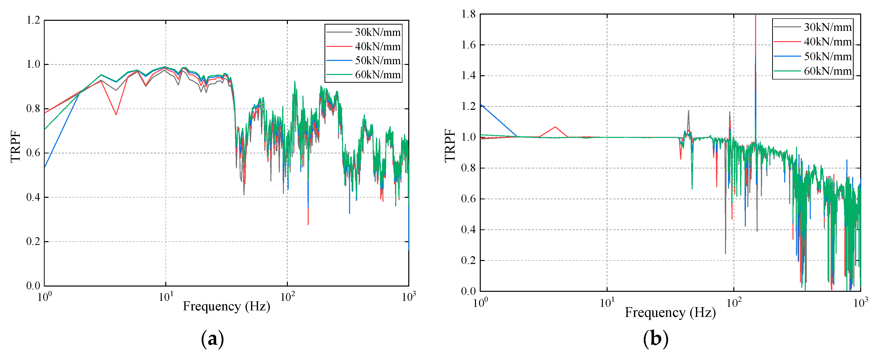
The TRPFs of the track structure applying different stiffness of fasteners are shown in Figure 11. Figure 11a demonstrates that the TRPFs from the rail to the composite slab are all below 1.0 among the frequency range considered and increase with the growth of the stiffness of fasteners except for some frequencies. Especially among the frequency range of 5 Hz to 37 Hz, the variations of the TRPFs can be seen obviously. Moreover, the TRPFs of 60 kN/mm reach to the maximum among the frequency range considered.
From Figure 11b, it can be observed that the TRPFs from the composite slab to the base slab are close to 1.0 when the frequency is below 37 Hz. Except for some frequencies, the TRPFs of four conditions are basically smaller than 1.0 and have few differences. What’s more, the maximum TRPFs appear at the frequency of 148 Hz, which reaches 1.79 when employing the fasteners with stiffness of 40 kN/mm. Nevertheless, the TRPFs of four conditions all show a downward trend when the frequency is larger than 148 Hz.
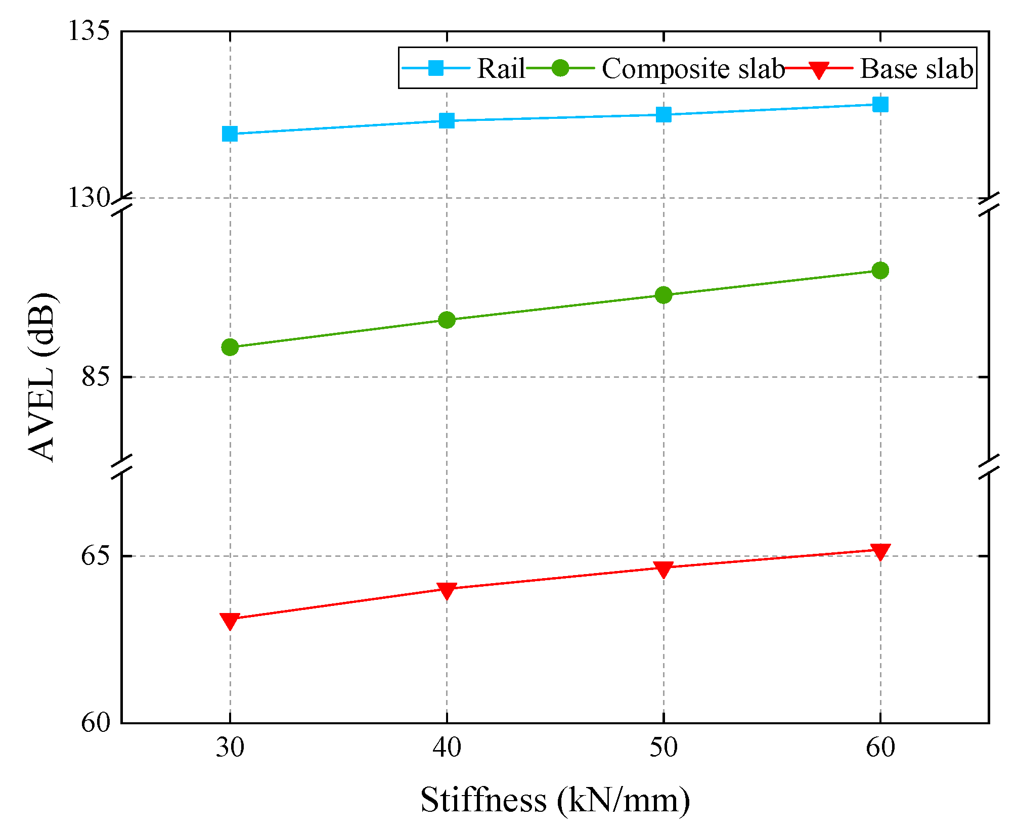
The AVEL of the track structure is demonstrated in Figure 12. It indicates that the AVELs of the track structure decrease with the growth of the stiffness of fasteners. What’s more, the increments of the composite slab and the base slab are more obvious than those of the rail. The increasing of the stiffness of fasteners causes that the vibration energy stored in the track structure increase. As a consequence, the AVEL of the track structure is sensitive to the variations of the stiffness of fasteners.
It can be concluded that with the rising of the stiffness of fasteners, the vibration energy stored in the track structure increase, and the increments of the composite slab and the base slab are more obvious.

3.3. The Influence of the Stiffness of Rubber Damping Pads on the Power Flow

In order to investigate the influence of the stiffness of rubber damping pad on the power flow, four kinds of stiffness are chosen, which are 200 MPa/m, 400 MPa/m, 600 MPa/m, and 800 MPa/m. In addition, the power flows, the TRPFs, and the AVELs are compared under these four conditions.
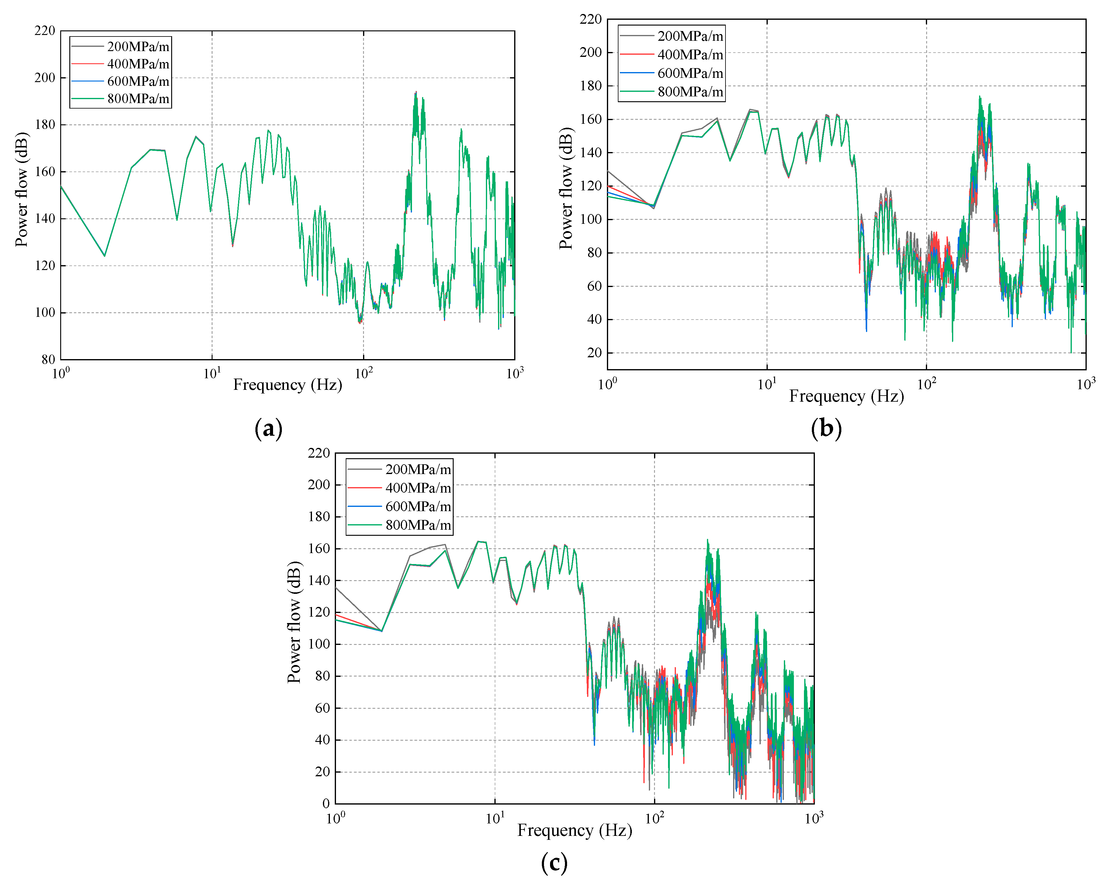
The power flows of the track structure with four kinds of stiffness is shown in Figure 13. It can be clearly seen from Figure 13a that the power flows of the rail nearly have no difference under four conditions, that is, the variations of the stiffness of the rubber damping pads cannot affect the power flows of the rail.
Figure 13b illustrates that the power flows of the composite slab with the stiffness of 200 MPa/m are the maximum when the frequency is below 9 Hz, and the power flows of 800 MPa/m reach to the minimum in the frequency range of 46 to 156 Hz. However, the power flows of 800 MPa/m are the maximum among the frequency range of 165 to 480 Hz. Except for those frequency ranges mentioned above, the power flows under four conditions exhibit very small deviations.
It can be observed from Figure 13c that the power flows of the base slab with the stiffness of 200 MPa/m are the maximum in the frequency ranges of 1 to 8 Hz and 39 to 107 Hz. Moreover, the power flows of 800 MPa/m reach the maximum at the frequency range of 166 to 1000 Hz, but the power flows of 800 MPa/m achieve the minimum among the frequency ranges of 46 to 76 Hz and 96 to 123 Hz. What’s more, it can be found that the power flows of the base slab increase with the rising of the stiffness of the rubber damping pads at the higher frequency.
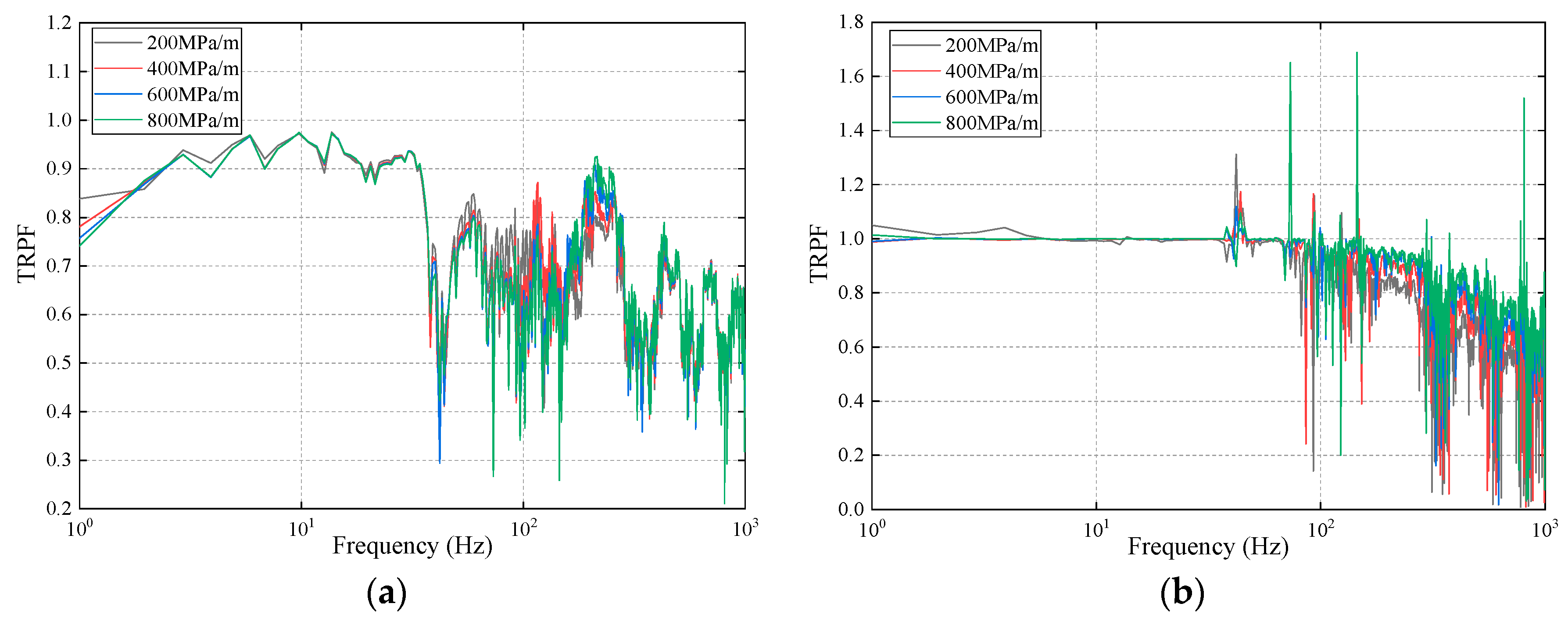
The TRPF of the track structure under four conditions is demonstrated in Figure 14. It can be found from Figure 14a that the TRPF from the rail to the composite slab is all below 1.0 in the frequency range considered. The TRPF of 800 MPa/m reaches the minimum in the frequency ranges of 3 to 10 Hz, 18 to 30 Hz, and 48 to 162 Hz, on the contrary, the TRPF of 800 MPa/m is the maximum at the frequency range of 166 to 490 Hz. In other frequency ranges, the TRPF shows few differences.
Figure 14b indicates that the TRPF from the composite slab to the base slab is basically below 1.0 except some frequencies. And the TRPF increases with the growth of the stiffness of rubber damping pads on the whole. It can be found that the bigger stiffness makes more energy transfer from the composite slab to the base slab, which goes against the reduction of ambient vibration.
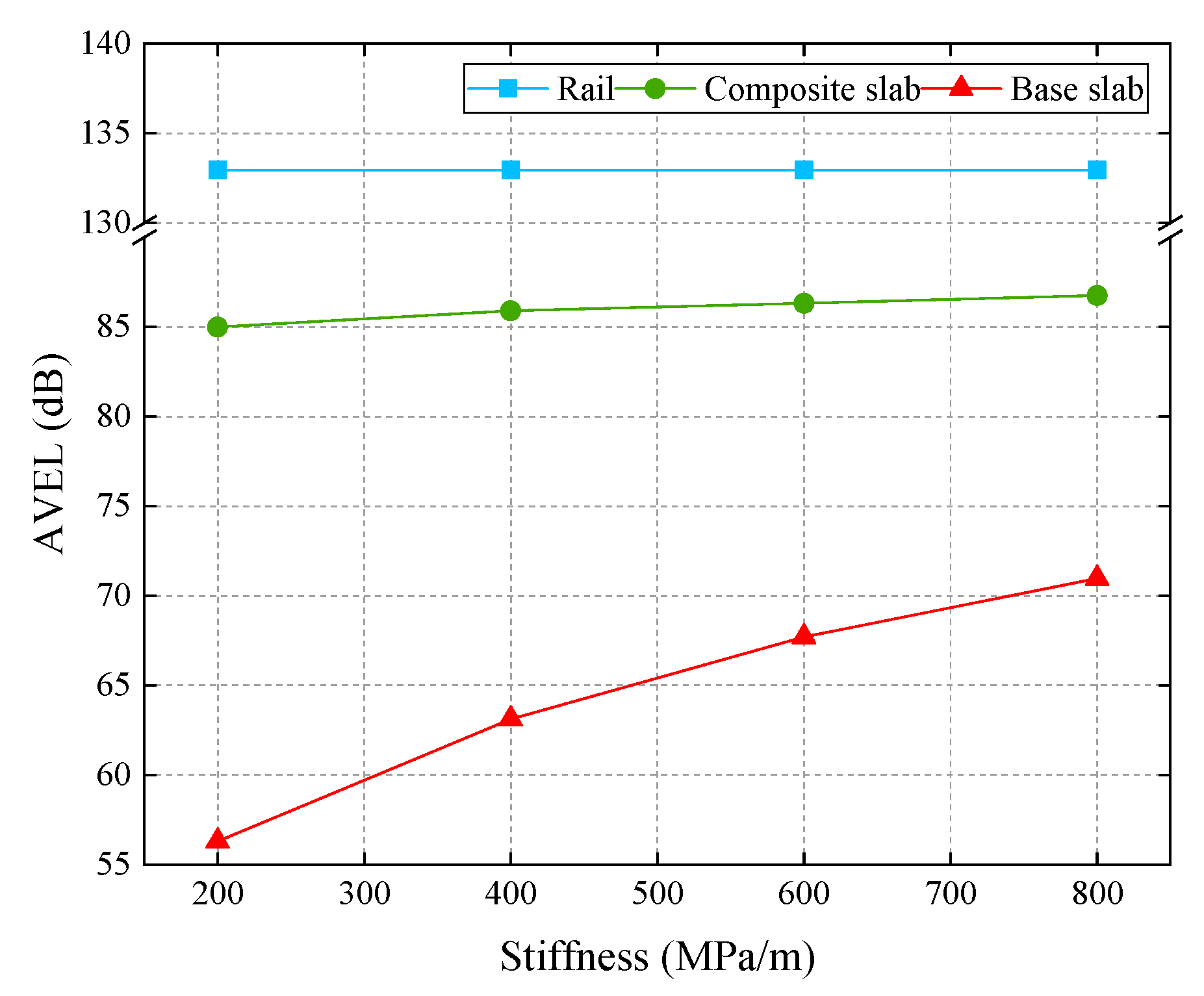
The AVEL is illustrated in Figure 15. It can be clearly found from Figure 15 that the AVELs of the base slab increase obviously with rising of the stiffness of rubber damping pads, and those of the composite slab also increase with the growth of the stiffness. However, the AVELs of the rail barely change with the variations of stiffness. As a result, the AVELs of the composite slab and the base slab are more sensitive to the variations of the stiffness of rubber damping pads than those of the rail.
Overall, it can be clearly found that the variations of the stiffness of rubber damping pads have little influence on the vibration energy stored in the rail. However, with the growth of the stiffness of rubber damping pads, the vibration energy stored in the composite slab and the base slab both increases. Among both, the changes of the base slab are particularly evident.

4. Conclusions

According to the rigid-flexible coupling dynamic theory, the vehicle-track-subgrade model is established to investigate the vibration-energy properties of the track structure under irregularities and different stiffness of fasteners and rubber damping pads. Furthermore, the detailed conclusions are drawn as follows:
(1) The vibration energy decreases from top to bottom of the track structure among the frequency considered, and the decreasing trend is obvious. The occurrence of the phenomenon is because the vibration energy, which is generated by the interaction of the wheel and the rail, is stored and consumed partly in every structure in the process of transferring from top to bottom.
(2) With the increase of the stiffness of fasteners, the vibration energy of the rail, the composite slab, and the base slab increase as well. In other words, the vibration energy of the track structure is sensitive to the stiffness of fasteners. Moreover, it also can be concluded that with the rising of the stiffness of fasteners, the vibration energy stored in the track structure augments likewise. Therefore, the fasteners employed should have reasonable stiffness, because the bigger stiffness will make the ambient vibration increase while the smaller stiffness will influence the running stability of vehicles even induce the rail corrugation. Based on that, the proposed value of the stiffness of the fasteners for the case under this study is 40 kN/mm.
(3) With the growth of the stiffness of rubber damping pads, the vibration energy of the rail has no variations basically, but the vibration energy of the composite slab and the base slab both increases. In addition, the variations of the base slab are particularly evident. Namely, the vibration energy of the composite slab and the base slab is more sensitive to the stiffness of rubber damping pads than that of the rail. As a result, the rubber damping pads applied is supported to have suitable stiffness, because the bigger stiffness will make the ambient vibration increase while the small stiffness will not be conducive to maintaining the track geometry. Based on that, the proposed value of the stiffness of the rubber damping pads for the case under this study is 400 MPa/m.
The conclusions drawn in this paper can provide a new perspective and method to study the vibration-energy properties and select the reasonable stiffness of the fasteners and the rubber damping pads of the CRTS-III track. Furthermore, this method can be also employed to study the vibration-energy properties of other type track structures in the HRS system.
Author Contributions

All authors contributed equally to this article. All authors have read and agreed to the published version of the manuscript.

Funding

This research was funded by the National Natural Science Foundation of China under Grant 51827813 and by the Key Program of National Natural Science Foundation of China under Grant U1734206.

Acknowledgments

The authors would like to thank the anonymous reviewers and Yinan Zhao for their valuable comments and advice.

Conflicts of Interest

The authors declare no conflicts of interest.

References

  1. Tang, L.; Kong, X.; Li, S.; Ling, X.; Ye, Y.; Tian, S. A preliminary investigation of vibration mitigation technique for the high-speed railway in seasonally frozen regions. Soil Dyn. Earthq. Eng. 2019, 127, 105841. [Google Scholar] [CrossRef]
  2. Rådeström, S.; Ülker-Kaustell, M.; Andersson, A.; Tell, V.; Karoumi, R. Application of fluid viscous dampers to mitigate vibrations of high-speed railway bridges. Int. J. Rail Transp. 2017, 5, 47–62. [Google Scholar] [CrossRef]
  3. Ferreira, P.A.; López-Pita, A. Numerical modelling of high speed train/track system for the reduction of vibration levels and maintenance needs of railway tracks. Constr. Build. Mater. 2015, 79, 14–21. [Google Scholar] [CrossRef]
  4. Olivier, B.; Connolly, D.P.; Alves Costa, P.; Kouroussis, G. The effect of embankment on high speed rail ground vibrations. Int. J. Rail Transp. 2016, 4, 229–246. [Google Scholar] [CrossRef]
  5. Liu, L.; Song, R.; Zhou, Y.; Qin, J. Noise and Vibration Mitigation Performance of Damping Pad under CRTS-III Ballastless Track in High Speed Rail Viaduct. KSCE J. Civ. Eng. 2019, 23, 3525–3534. [Google Scholar] [CrossRef]
  6. Yu, Z.; Xie, Y.; Shan, Z.; Li, X. Fatigue performance of CRTS III slab ballastless track structure un-der High-speed train load based on concrete fatigue damage constitu-tive law. J. Adv. Concr. Technol. 2018, 16, 233–249. [Google Scholar] [CrossRef] [Green Version]
  7. Xin, T.; Gao, L. Reducing slab track vibration into bridge using elastic materials in high speed railway. J. Sound Vib. 2011, 330, 2237–2248. [Google Scholar] [CrossRef] [Green Version]
  8. Zhao, C.; Wang, P. Experimental study on the vibration damping performance of rubber absorbers for ballastless tracks on viaduct. China Railw. Sci. 2013, 34, 8–13. [Google Scholar]
  9. Ren, J.J.; Zhao, H.W.; Li, X.; Xu, K. Analysis of harmonic response of CRTS III prefabricated slab track with anti-vibration structure. J. Railw. Eng. Soc. 2016, 33, 44–50. [Google Scholar]
  10. Xin, T.; Zhang, Q.; Gao, L.; Zhao, L.; Qu, J. Dynamic effect and structure optimization of damping layers of CRTS III slab ballastless track for high speed railway. China Railw. Sci. 2016, 37, 8–13. [Google Scholar]
  11. Zhao, C.; Ping, W. Effect of elastic rubber mats on the reduction of vibration and noise in high-speed elevated railway systems. Proc. Inst. Mech. Eng. Part F J. Rail Rapid Trans. 2018, 232, 1837–1851. [Google Scholar] [CrossRef]
  12. Goyder, H.G.D.; White, R.G. Vibrational power flow from machines into built-up structures, part I: Introduction and approximate analyses of beam and plate-like foundations. J. Sound Vib. 1980, 68, 59–75. [Google Scholar] [CrossRef]
  13. Goyder, H.G.D.; White, R.G. Vibrational power flow from machines into built-up structures, part II: Wave propagation and power flow in beam-stiffened plates. J. Sound Vib. 1980, 68, 77–96. [Google Scholar] [CrossRef]
  14. Goyder, H.G.D.; White, R.G. Vibrational power flow from machines into built-up structures, part III: Power flow through isolation systems. J. Sound Vib. 1980, 68, 97–117. [Google Scholar] [CrossRef]
  15. Petersson, B.; Plunt, J. On effective mobilities in the prediction of structure-borne sound transmission between a source structure and a receiving structure, part I: Theoretical background and basic experimental studies. J. Sound Vib. 1982, 82, 517–529. [Google Scholar] [CrossRef]
  16. Hussein, M.F.M.; Hunt, H.E.M. A power flow method for evaluating vibration from underground railways. J. Sound Vib. 2006, 293, 667–679. [Google Scholar] [CrossRef]
  17. Li, Q.; Wu, D.J. Analysis of the dominant vibration frequencies of rail bridges for structure-borne noise using a power flow method. J. Sound Vib. 2013, 332, 4153–4163. [Google Scholar] [CrossRef]
  18. Eberhard, P.; Schiehlen, W. Computational Dynamics of Multibody Systems: History, Formalisms, and Applications. J. Comput. Nonlin Dyn. 2005, 1, 3–12. [Google Scholar] [CrossRef]
  19. GUYAN, R.J. Reduction of stiffness and mass matrices. AIAA J. 1965, 3, 380. [Google Scholar] [CrossRef]
  20. Hertz, H. Verhandlungen des Vereins zur Beförderung des Gewerbefleisses; Duncker: Wien, Austria, 1882; pp. 174–196. [Google Scholar]
  21. Kalker, J.J. A fast algorithm for the simplified theory of rolling contact. Veh. Syst. Dyn. 1982, 11, 1–13. [Google Scholar] [CrossRef]
  22. Lou, P.; Gong, K.; Zhao, C.; Xu, Q.; Luo, R.K. Dynamic Responses of Vehicle-CRTS III Slab Track System and Vehicle Running Safety Subjected to Uniform Seismic Excitation. Shock Vib. 2019, 2019, 12. [Google Scholar] [CrossRef] [Green Version]
  23. Li, W.L.; Lavrich, P. Prediction of power flows through machine vibration isolators. J. Sound Vib. 1999, 224, 757–774. [Google Scholar] [CrossRef]
Figure 1. The illustration of the analysis of the vibration-energy properties of the track structure.
Symmetry 12 00069 g001
Figure 2. The vehicle model.
Symmetry 12 00069 g002
Figure 3. The track model.
Symmetry 12 00069 g003
Figure 4. The vehicle-track-subgrade coupling model.
Symmetry 12 00069 g004
Figure 5. The time-domain and frequency-domain of the nodes’ force and velocity. (a) and (b) are the time-domain results; (c) and (d) are the frequency-domain results.
Symmetry 12 00069 g005
Figure 6. The vertical transfer of the power flow.
Symmetry 12 00069 g006
Figure 7. The power flow of the track structure.
Symmetry 12 00069 g007
Figure 8. The transfer rate of the power flow (TRPFs) (a) from the rail to the composite slab and (b) from the composite concrete to the base slab.
Symmetry 12 00069 g008
Figure 9. The average vibration energy level (AVEL) of the track structure.
Symmetry 12 00069 g009
Figure 10. The power flows of (a) the rail, (b) the composite slab, and (c) the base slab.
Symmetry 12 00069 g010
Figure 11. The TRPFs (a) from the rail to the composite slab and (b) from the composite slab to the base slab.
Symmetry 12 00069 g011
Figure 12. The AVEL of the track structure.
Symmetry 12 00069 g012
Figure 13. The power flows of (a) the rail, (b) the composite slab, and (c) the base slab.
Symmetry 12 00069 g013
Figure 14. The TRPFs (a) from the rail to the composite slab and (b) from the composite slab to the base slab.
Symmetry 12 00069 g014
Figure 15. The AVEL of the track structure.
Symmetry 12 00069 g015
Table 1. The parameters of the CRH2 vehicle.
ParametersUnitValue
Mass of car bodykg33,200
Moment of inertia of car body frame about the x-axis/y-axis/z-axis kg·m21.076 × 105/1.571 × 106/1.402 × 106
Mass of bogiekg2600
Moment of inertia of bogie frame about the x-axis/y-axis/z-axis kg·m22106/1424/2600
Mass of wheelsetkg1970
Moment of inertia of wheelset about the x-axis/y-axis/z-axiskg·m2623/78/623
Longitudinal/lateral/vertical stiffness of primary suspensionkN/m980/980/1176
Longitudinal/lateral/vertical damping of primary suspensionkN·s/m0/0/19.6
Longitudinal/lateral/vertical stiffness of secondary suspensionkN/m178.4/193.1/193.1
Longitudinal/lateral/vertical damping of secondary suspensionkN·s/m58.8/58.8/98
Axle distancem2.5
Bogie distance m17.5
Rolling radius m0.43
Table 2. The parameters of the track.
ParametersUnit Value
Density of railkg/m37850
Elastic modulus of railN/m22.059 × 1011
Vertical/lateral stiffness of fastenerN/m2.5 × 107/5 × 107
Vertical/lateral damping of fastenerN·s/m2.6 × 104/1.24 × 104
Density of slab/self-compacting concrete/base slabkg/m32500/2500/2500
Elastic modulus of slabN/m23.65 × 1010
Elastic modulus of self-compacting concreteN/m23.25 × 1010
Elastic modulus of base slabN/m23.25 × 1010
Surface stiffness of rubber damping padMPa/m400
Surface damping of rubber damping padPa·s/m3.43 × 104
Density of subgradekg/m31750
Elastic modulus of subgradeN/m21.4 × 108
Table 3. The maximum values of dynamic responses.
Dynamic ResponsesWheel-Rail Vertical Force (kN)Rail Vertical Displacement (mm)Base Slab Vertical Acceleration (g)
Lou et al. [22]102.50.800.23
This paper106.60.830.21