Abstract
Aiming to successfully meet the requirements of a large output torque and a wide range of flux weakening speed expansion in permanent magnet synchronous motors (PMSM) for electric vehicles, a novel surface insert permanent magnet synchronous motor (SIPMSM) is developed. The method of notching auxiliary slots between the magnetic poles in the rotor and unequal thickness magnetic poles is proposed to improve the performance of the motor. By analyzing the magnetic circuit characteristics of the novel SIPMSM, the notching auxiliary slots between the adjacent magnetic poles can affect the q-axis inductance, and the shape of magnetic pole effects the d-axis inductance of the motor. The combined action of the two factors not only weakens the cogging torque, but also improves the flux weakening capability of the motor. In this paper, the response surface methodology (RSM) is used to establish a mathematical model of the relationship between the structural parameters of the motor and the optimization objectives, and the optimal design of the motor is completed by solving the mathematical model. Experimental validation has been conducted to show the correctness and effectiveness of the proposed SIPMSM.
1. Introduction
With the rapid development of the automobile industry, the two global problems of environmental pollution and energy shortage are becoming more and more serious. Under such a severe situation, many countries have begun to formulate plans to ban the sale of fuel vehicles. Electric vehicles are powered by electricity and have the advantages of zero emission, low noise and energy saving. Therefore, the development and promotion of electric vehicles is highly valued by governments all over the world [1].
As the core component of electric vehicle, the performance of the driving motor directly affects the performance of electric vehicles. The research and development of high-performance electric vehicle drive motors has become one of the important factors restricting the development of electric vehicles [2]. The main types of drive motors for electric vehicles are brushless DC motors, induction motors, switched reluctance motors and permanent magnet synchronous motors (PMSM). The PMSM has a series of advantages, such as a simple structure, high efficiency and excellent performance of flux-weakening speed expansion—making it more and more widely used as an electric vehicle drive motor in recent years [3]. However, for PMSM, the magnetic energy generated by the permanent magnet will interact with the stator slot, which will produce the slot effect, increase the harmonic content in the air gap, and reduce the control accuracy of the drive system. Therefore, reducing the cogging torque and improving the performance of flux-weakening speed expansion are the important research contents of PMSM for electric vehicles.
The cogging torque is reduced by changing the size and shape of the magnetic barrier of PMSM [4]. The auxiliary slot in the stator of the surface mounted PMSM is designed, and the mathematical model of the size of the auxiliary slot is established [5,6]. Through the analytical mathematical model, the cogging torque of the motor is optimized. A method of the axial combination of different permanent magnets in a rotor is proposed to reduce harmonic content in airgap and torque ripple [7]. Stator tooth modification is used to reduce the harmonic content of the teeth, thereby reducing the eddy current loss and vibration noise, and improving the efficiency of the motor [8,9,10]. In summary, most of the structure optimization methods of PMSM are based on a single parameter or index. The optimization values are determined by the parameters, then the other structure parameters are optimized one by one, and, finally, the optimized parameters are combined.
However, PMSM is difficult to obtain the optimal results by optimizing a single index or parameter. The Taguchi method is used to optimize the shape of permanent magnet, which improves the efficiency and reduces the torque ripple of the motor [11]. However, the optimal value obtained by this method can only be a combination of the levels used in the experiment, and the optimal result has certain limitations. A genetic algorithm is used to optimize the structural parameters of the interior asymmetric V type magnetic pole, which reduces the torque ripple of the motor [12]. However, the genetic algorithm can easily fall into the extreme point near the optimal solution in the later stage of calculation, so the results obtained by this method tend to approach the optimal solution rather than the optimal value. A particle swarm optimization algorithm is used to optimize the piecewise width and pole arc coefficient of the permanent magnet of the surface mounted PMSM, which improves the output characteristics of the motor [13]. However, the disadvantage of the particle swarm optimization algorithm is that the optimal results can easily fall into the problem of local optimum [14]. The structure optimization of flexible rotor of hollow traveling wave ultrasonic motor is carried out based on response surface methodology (RSM), and the experiment results verify the correctness of the optimization method. The correctness of the optimization method is verified by the experiment. RSM is used to optimize the design of slotless permanent magnet linear synchronous motor to increase the average reasoning and reduce the torque ripple [15]. The accuracy of RSM design method is verified by experiments. The emergence of RSM is the result of the close connection of statistics, mathematics and computer science. Owing to this optimization method takes many factors into account and it establishes complex multi-dimensional surface which is closer to the actual situation than other optimization methods, response surface method is widely used, so RSM is widely used in practical engineering.
In this paper, a novel surface insert permanent magnet synchronous motor (SIPMSM) is proposed, and the primary design parameters of the motor are determined by empirical formulas. By establishing the mathematical model of the cogging torque and inductance of the magnetic circuit of the SIPMSM, the influence factors of the cogging torque and flux-weakening speed expansion of the developed SIPMSM are deduced. Then the multi-objective mathematical model of the relationship between the structural parameters and the influencing factors of the motor is established by RSM. Optimal structural parameters are obtained by solving the mathematical model. Lastly, the traditional SIPMSM and the novel SIPMSM are trial-manufactured and compared.
2. The Proposed SIPMSM
2.1. Structure Design
The shape of magnetic pole effects the output characteristics of PMSM directly. The permanent magnet of typical SIPMSM is a tile shape with inner and outer arc centers at the same point—as shown in Figure 1. A PMSM with this kind of magnetic pole usually has the disadvantages of large cogging torque, large leakage and poor flux weakening capability [16]. Therefore, a novel SIPMSM is developed, as shown in Figure 2. The permanent magnet in the novel SIPMSM is an unequal thickness magnetic pole with different inner and outer radians, which results in the uneven distribution of the radial air-gap flux density and remarkable magnetic congregate effect. In order to reduce the leakage flux and the high harmonic content in the air-gap, an auxiliary slot is notched in the rotor, as shown in Figure 3.
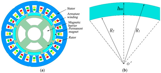
Figure 1.
Schematic diagram of typical SIPMSM and tile shape magnetic poles. (a) Schematic diagram of traditional SIPMSM; (b) Schematic diagram of tile shape magnetic poles.
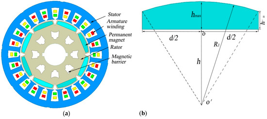
Figure 2.
Schematic diagram of the novel SIPMSM and unequal thickness magnetic poles. (a) Schematic diagram of the novel SIPMSM; (b) Schematic diagram of unequal thickness magnetic poles.
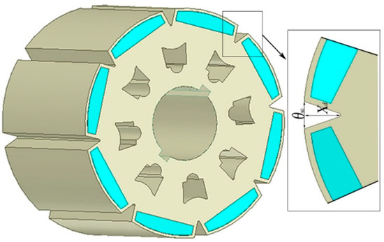
Figure 3.
Schematic diagram of auxiliary slot in rotor.
According to the performance requirements of PMSM for electric vehicles, the structure parameters of the novel SIPMSM are determined by using the empirical formula (see Table 1).

Table 1.
Initial Design Parameters of the novel SIPMSM.
2.2. Infulence on Cogging Torque
Compared with the traditional SIPMSM, the shape of the auxiliary slot and the unequal thickness of the permanent magnet between magnetic poles changes the harmonic content in the air gap flux density, which inevitably affects the cogging torque. In this paper, a mathematical model of the cogging torque of the novel SIPMSM is established based on the energy method, and the influence of auxiliary slot in the rotor on the cogging torque is analyzed.
The cogging torque is defined as the negative derivative of the magnetic field energy, relative to the position angle when the armature winding does not turn on the current [17]. The cogging torque of the permanent magnet motor can be expressed as
where E is the energy of the magnetic field in the air-gap; B is the air-gap flux density; V is the volume of air-gap between stator and rotor; α is the relative position angle between stator and rotor.
The energy of the air-gap magnetic field can be expressed as
where θ is the angle between the air-gap magnetic density and the central line of the magnetic pole; is vacuum permeability. The mathematical model of air-gap density distribution along the rotor surface with the unequal thickness magnetic pole is expressed as
where, is the distribution of the remanence of permanent magnet along the circumferential direction; is the distribution of effective air-gap length along the circumferential direction; is the distribution of the direction of magnetization along the circumferential direction at the minimum thickness of permanent magnet.
Substituting (2) into the E, we obtain
Perform Fourier decomposition of without considering the influence of the relative position of stator and rotor.
where, p is the number of pole pairs and is polar arc coefficient.
By Fourier transform formula , we can get
Substituted (2), (3), (4) and (5) into (1) and the expression of cogging torque is obtained by integrating the trigonometric functions within [0, 2π].
where La is the axial length of the motor; R1 is the outer arc radius of unequal thickness magnetic poles; h is the vertical distance from the center of the outer arc to the permanent magnet; n is an integer that makes (nz/2p) an integer.
According to the triangle similarity theorem, one can get
where hmax is the maximum thickness of permanent magnet; is the minimum thickness of permanent magnet; d is the width of permanent magnet.
Substitute (8) into (7), then the cogging torque expression of the SIPMSM with unequal thickness magnetic poles can be described as
When the auxiliary slot is notched between the magnetic poles, the back EMF and magnetic field distribution of the motor will be greatly affected, and the high-order harmonic content in the air-gap flux density will be reduced, so the cogging torque of the motor will be weakened [18].
When the number of auxiliary slots is k, the Fourier decomposition coefficients of in the can be expressed as:
where is the width of auxiliary slot in the rotor, Xd is auxiliary slot in rotor, and k = 1.
By substituting (10) into (9), the expression of cogging torque with slots between magnetic poles of unequal thickness can be obtained as
From (11), it can be seen that the structural parameters affecting the cogging torque include the axial length of the motor, the number of pole pairs, the maximum thickness of permanent magnet, the minimum thickness of permanent magnet, the width of permanent magnet, the width of slotting, the depth of the auxiliary slot and the number of stator slots. This paper mainly studies the influence of the notching auxiliary slot between adjacent magnetic poles.
2.3. Influence of Notching Auxiliary Slots
The auxiliary slots will increase the magnetic reluctance of the q axis magnetic circuit of SIPMSM. On the one hand, the difference of inductance between the d and q axis will produce reluctance torque. On the other hand, increasing the d axis inductance or reducing the q axis inductance can improve the flux weakening capability of the motor [19,20]. This section mainly studies the influence of the shape of unequal thickness magnetic poles and size of auxiliary slots on the flux weakening capability of the motor.
When the speed of PMSM exceeds the base speed, the phase current and phase voltage will reach the maximum value. In order to ensure that the limiting voltage does not exceed the limit voltage of the controller, the flux weakening control of PMSM is needed [21,22]. When the motor reaches the maximum speed, the stator current is used to weaken the magnetic field. The voltage amplitude is equal to the voltage limit of the controller. It can be seen that the d and q axis voltage in the rotating coordinate system can be expressed as:
where ud is the voltage of d axis; uq is the voltage of q axis; Rs is the resistance of armature winding; id is the current of d axis; iq is the current of q axis; Ψd is the flux linkage of d axis; Ψq is the flux linkage of q axis; ω is the angular speed of rotor rotation.
The change of current and flux linkage is zero when the motor is in steady state, so the steady state d and q axis voltage equation of the motor is obtained as:
When the motor is controlled by flux weakening control, the base speed of the motor can be expressed as:
where is the limit voltage; is the flux linkage of permanent magnet; is the d axis inductance of motor; is the q axis inductance of motor.
When the output current of the inverter is all d axis demagnetizing current, that is iq = 0. The ideal maximum speed of the motor can be expressed as
According to (14), the expansion of the weakening speed of the magnetic flux can be improved by reducing the permanent magnetic flux chain and increasing the d-axis inductance or reducing the q-axis inductance. According to (15), the expansion of the weakening speed of the magnetic flux can also be improved by increasing the limiting current and limiting voltage. Therefore, this paper mainly changes the inductance of the d and q-axis magnetic circuits by optimizing the design of unequal thickness magnetic poles and the slot size of the rotor. Changing these inductances can improve the performance of magnetic flux weakening speed. The ratio of the maximum speed to the base speed is the flux weakening expansion rate [23]. The expression of the flux weakening speed expansion can be expressed as:
Inductance is a physical quantity to measure the ability of a coil to produce electromagnetic induction, and it is the flux linkage produced by the unit current [24]. According to the definition, we can get the inductance of SIPMSM
where Fc is the magnetomotive of permanent magnet; RM is the magnetic resistance of magnetic circuit through which the self-induction flux; N is the number of turns of conductor.
The expressions for calculating the d axis inductance of the novel SIPMSM as:
where, Rr is the magnetic resistance at the maximum thickness of permanent magnet steel; Rz is the rotor core magnetic resistance between the permanent magnet steel and the air-gap; Ra is the magnetic resistance of the air-gap; Rs is the magnetic resistance of stator; Ry is the magnetic resistance of the stator yoke.
The expressions for calculating the q axis inductance of the novel SIPMSM as:
where, Rd is the magnetic resistance of auxiliary slot.
The developed SIPMSM adopts the asymmetric magnetic circuit; the d axis flux linkage passes through unequal thickness magnetic poles, rotor core and air-gap, stator teeth and stator yoke; the q axis flux linkage passes through the slot of slot, air-gap, stator boots and stator yoke. Due to large magnetic resistance of permanent magnet, the thickness of magnetic poles is approximately equal to the air-gap. When the auxiliary slot is notched between the magnetic poles in the rotor, the inductance in the q axis decreases with the increase in the depth of the auxiliary slot.
In summary, the depth of the auxiliary slot and maximum thickness of the permanent magnet influence the cogging torque and flux weakening speed expansion. This paper will optimize these two parameters.
3. Optimization Model
In the proposed SIPMSM, the complicated rotor topology and different saturation degree of the iron core make it difficult to solve the relationship between the object and the independent variables by analytic method. Because of the flexibility of the real response surface and the interaction between factors, the second order or higher order model is usually used to approximate the response objective function. The relationship between the maximum thickness of permanent magnet hmax, the depth of auxiliary slot Xd, the cogging torque Tcog and the flux weakening expansion rate ρ can be obtained by the combination of RSM and finite element method. The experimental arrangements and finite elements results are shown in Table 2, where X1 and X2 are the factor coded values, Y1 is the cogging torque, and Y2 is the flux weakening expansion rate. The second-order model can be expressed as follows:
where xi is the coded variables; βi is the linear effect of xi; βij is the interaction between xi and xj; βii is the quadratic effect of xi.

Table 2.
The design matrix and finite elements results.
Because of the space limitation of rotor, the parameter level is limited in a certain range. Therefore, the central composite surface design (CCF) is adopted in this paper. All test points do not exceed the requirements of the cube and meet the design requirements [25,26,27].
The regression models of Y1 and Y2 are analyzed using Design-Expert software. According to the regression model equation, the response surface and contour map of the interaction factors to peak value of cogging torque and flux magnetic speed expansion can be established, as shown in Figure 4 and Figure 5.
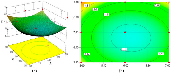
Figure 4.
Effect of interaction factors on peak value of cogging torque Y1: (a) 3D and (b) 2D contours.
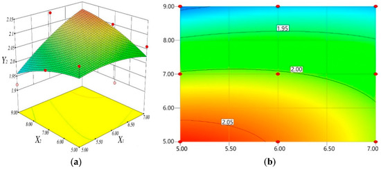
Figure 5.
Effect of interaction factors on peak value of cogging torque Y2: (a) 3D and (b) 2D contours.
It can be seen from Figure 4, when x1 varies from 5 to 7 mm, the peak value of the cogging torque decreases first and then increases. If x1 is fixed at a certain level, the peak value of the cogging torque decreases first and then increases. Therefore, according to the analysis of partial regression equation and contour plot, the effect of the depth of auxiliary slot in rotor on the flux magnetic speed expansion is greater than the maximum thickness of the permanent magnet.
It can be seen from Figure 5, when x1 changes from 5 to 7 mm, the value of flux weakening expansion ratio of the motor increases first and then decreases. If x1 is fixed at a certain level, with the increase in x2, the peak value of cogging torque trends to decrease. Therefore, according to the analysis of partial regression equation and the contour plot, the effect of the maximum thickness of the permanent magnet is greater than the depth of auxiliary slot in the rotor.
In the motor design, the cogging torque is always expected to be small, while the flux weakening speed expansion is always expected to be large. So, a quasi-function is constructed using RSM. The relationship between independent variables and response variables in the motor and the nonlinearity is solved by solving the mathematical model for multi-objective optimization. Thus, the global solution of optimization calculation is obtained: (hmax, Xd) = (6.40, 7). The optimal response is (Tcog, ρ) = (1.16, 2.08).
4. Experimental Validation
In order to verify the correctness of the optimization design and the superiority of the novel SIPMSM. In this paper, two SIPMSMs with the same-rated parameters were trial-produced, as shown in Figure 6 and Figure 7. The optimum design structures of traditional SIPMSM and the novel SIPMSM were tested and verified, and the performance of the test results was compared. The structure of the stator, winding layout, outer diameter of rotor, volume of permanent magnet and pole arc coefficient of the two motors are the same—the main difference between the two motors is that the maximum thickness of the rotor pole and slotting structure are different.

Figure 6.
The rotor structure of traditional SIPMSM.
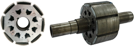
Figure 7.
The rotor structure of the novel SIPMSM.
The two prototypes were tested on the eddy current dynamometer, as shown in Figure 8. With the increase in the motor speed, the load increases continuously, so that the motor current reaches the limit value. Then the sensor detects and collects signals. Finally, the output characteristic curve and efficiency map of the two SIPMSMs are shown in Figure 9 and Figure 10.
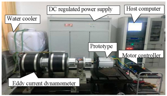
Figure 8.
Test platform of prototype.
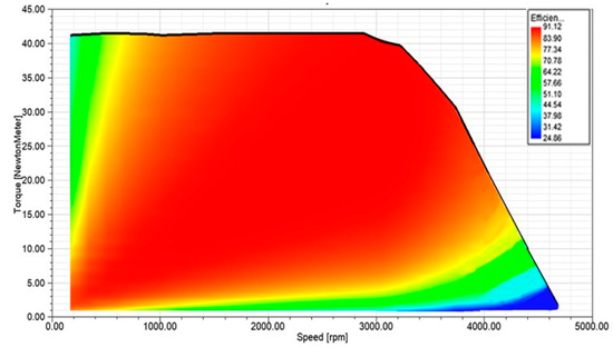
Figure 9.
Efficiency map and characteristic curve of traditional SIPMSM.
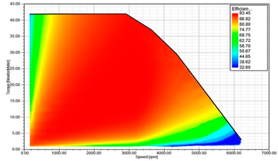
Figure 10.
Efficiency map and characteristic curve of the novel SIPMSM.
Compared with Figure 9 and Figure 10, it can be seen that the maximum efficiency of the novel SIPMSM is 91.12%, and the maximum speed that can be achieved is only 4750 rpm, while the maximum efficiency of traditional SIPMSM is 93.45%, and the maximum speed is 6250 rpm. Moreover, the novel SIPMSM has a wider range of high efficiency working area, which shows that the novel SIPMSM has a better performance in terms of flux magnetic speed expansion, thus verifying the veracity of theoretical analysis.
At the same time, PMSM for electric vehicles needs a variable speed drive and wide speed range, because electric vehicles need to start and stop frequently at low speeds under traffic congestion conditions, and good acceleration performance is required when traffic is smooth or running on highways [28,29]. Obviously, the novel SIPMSM has this output characteristic.
Finally, the experiment on the torque ripple was tested on the test platform from startup to related load, and the test results are shown in Figure 11.
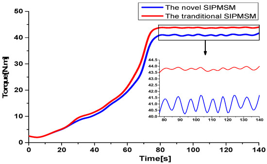
Figure 11.
Torque ripple comparison between motor startup and rated load.
From Figure 11, it can be seen that the output torque of the two SIPMSMs reaches a stable state at 77 s, owing to the same control mode and rated parameters. However, the output torque of the novel SIPMSM is clearly higher than the traditional SIPMSM. This is because the reasonable design of the permanent magnets with unequal thickness makes the air-gap magnetic field have a significant magnetic congregate effect and enhances the output torque. It is not difficult to see that the torque ripple of the novel SIPMSM is lower than the traditional SIPMSM when it reaches steady state.
Torque ripple of PMSM is composed of cogging torque and ripple torque [30]. However, ripple torque is mainly caused by the motor control mode. In order to control a single variable, this paper uses the same controller for two motors. In this case, torque ripple is only determined by the cogging torque. Compared with Figure 10 and Figure 11, it can be seen that the torque ripple of the novel SIPMSM is significantly lower than the traditional SIPMSM. Therefore, notching auxiliary slots in the rotor reduces the high order harmonic content in the air-gap flux density, weakens the cogging torque, and verifies the correctness of the design. The veracity of the theoretical analysis and optimization design is confirmed.
5. Conclusions
A novel SIPMSM by the method of notching auxiliary slots between the magnetic poles in the rotor and unequal thickness magnetic poles is developed. Compared with the traditional SIPMSM, it has the characteristics of large output torque, a wide range of speed regulation and a low cogging torque. The findings of the experimental results are described as follows:
- (1)
- The mathematical model of cogging torque of the novel SIPMSM is established, and the influence factors of the cogging torque and flux weakening speed expansion of the novel SIPMSM were deduced. Combining the RSM and finite element method, the multi-objective optimization design of the influencing factors was carried out. The optimization results show that when the maximum thickness of magnetic poles is 6.4mm and the depth of rotor slot is 7mm, the peak value of cogging torque is 1.16 nm and the flux weakening speed rate is 2.08.
- (2)
- The prototype test shows that—compared with the traditional SIPMSM—the new SIPMSM not only enhances the output torque and reduces the torque ripple, but also improves the performance of flux weakening speed expansion. At the same time, the high efficiency range of the constant power operation is widened, and more in line with the performance requirements of PMSM for electric vehicles. Therefore, the novel SIPMSM is more suitable for electric vehicles.
Author Contributions
S.M. and Y.L. conceived and designed the experiments; B.Q. and S.M. performed the experiments and wrote the paper; M.A.S. and Z.L. revised the paper; S.M., B.Q., M.A.S. and Z.L. analyzed the data. All authors have read and agreed to the published version of the manuscript.
Funding
The research was funded by the National Natural Science Foundation of China (No. 51875327, 51777055 and 51690181), the Natural Science Foundation of Shandong Province (No. ZR2018LE010 and ZR 2017MF045) and Australia ARC DECRA (No. DE190100931). And the APC was funded by 51777055.
Acknowledgments
The research is supported by the National Natural Science Foundation of China (No. 51875327, 51777055 and 51690181), the Natural Science Foundation of Shandong Province (No. ZR2018LE010 and ZR 2017MF045) and Australia ARC DECRA (No. DE190100931).
Conflicts of Interest
The authors declare no conflict of interest.
References
- Zhu, Z.Q.; Howe, D. Electrical Machines and Drives for Electric Hybrid and Fuel Cell Vehicles. IEEE Proc. 2007, 95, 746–765. [Google Scholar] [CrossRef]
- Zhang, X.; Du, Q.; Ma, S.; Geng, H.; Hu, W.; Li, Z.; Liu, G. Permeance Analysis and Calculation of the Double-Radial Rare-Earth Permanent Magnet Voltage-Stabilizing Generation Device. IEEE Access 2018, 6, 23939–23947. [Google Scholar] [CrossRef]
- Kim, K.; Lee, J.; Kim, H.; Koo, D. Multiobjective Optimal Design for Interior Permanent Magnet Synchronous Motor. IEEE Trans. Magn. 2009, 45, 1780–1783. [Google Scholar]
- Ping, J.; Shuhua, F.; Ho, S.-L. Distribution Characteristic and Combined Optimization of Maximum Cogging Torque of Surface-Mounted Permanent-Magnet Machines. IEEE Trans. Magn. 2018, 54, 1–5. [Google Scholar] [CrossRef]
- Xia, C.; Chen, Z.; Shi, T.; Wang, H. Cogging Torque Modeling and Analyzing for Surface-Mounted Permanent Magnet Machines with Auxiliary Slots. IEEE Trans. Magn. 2013, 49, 5112–5123. [Google Scholar] [CrossRef]
- Abbaszadeh, K.; Alam, F.R.; Teshnehlab, M. Slot opening optimization of surface mounted permanent magnet motor for cogging torque reduction. Energy Convers. Manag. 2012, 55, 108–115. [Google Scholar] [CrossRef]
- Bao, X.; Wu, C.; Fang, J. Cogging torque reduction in surface-mounted permanent magnet synchronous motor by combining different permanent magnets in axial direction. J. Electr. Eng. 2018, 33, 4231–4238. [Google Scholar]
- Hwang, S.M.; Eom, J.B.; Hwang, G.B.; Jeong, W.B.; Jung, Y. Cogging torque and acoustic noise reduction in permanent magnet motors by teeth pairing. IEEE Trans. Magn. 2000, 36, 3144–3146. [Google Scholar] [CrossRef]
- Kim, T.H.; Won, S.H.; Bong, K.; Lee, J. Reduction of cogging torque in flux-reversal machine by rotor teeth pairing. IEEE Trans. Magn. 2005, 41, 3964–3966. [Google Scholar]
- Song, J.; Dong, F.; Zhao, J.; Lu, S.; Dou, S.; Wang, H. Optimal Design of Permanent Magnet Linear Synchronous Motors Based on Taguchi Method. IET Electr. Power Appl. 2016, 11, 41–48. [Google Scholar] [CrossRef]
- Wang, H.; Qu, Z.; Tang, S.; Pang, M.; Zhang, M. Analysis and optimization of hybrid excitation permanent magnet synchronous generator for stand-alone power system. J. Magn. Magn. Mater. 2017, 436, 117–125. [Google Scholar] [CrossRef]
- Ren, W.; Xu, Q.; Li, Q. Asymmetrical V-Shape Rotor Configuration of an Interior Permanent Magnet Machine for Improving Torque Characteristics. IEEE Trans. Magn. 2015, 51, 1–4. [Google Scholar] [CrossRef]
- Niu, Z.; Sun, Z.; Chen, C.; Shi, Y. Optimization of the rotor structure of a hollow traveling wave ultrasonic motor based on response surface methodology and self-adaptive genetic algorithm. Proc. Chin. Soc. Electrical. Eng. 2014, 34, 5378–5385. [Google Scholar]
- Ashabani, M.; Mohamed, Y.A.-R.I. Multiobjective Shape Optimization of Segmented Pole Permanent-Magnet Synchronous Machines with Improved Torque Characteristics. IEEE Trans. Magn. 2011, 47, 795–804. [Google Scholar] [CrossRef]
- Kim, S.I.; Hong, J.P.; Kim, Y.K.; Nam, H.; Cho, H.I. Optimal design of slotless-type PMLSM considering multiple responses by response surface methodology. IEEE Trans. Magn. 2006, 42, 1219–1222. [Google Scholar]
- Si, M.; Yang, X.Y.; Zhao, S.W.; Gong, S. Design and analysis of a novel spoke-type permanent magnet synchronous motor. IET Electr. Power Appl. 2016, 10, 571–580. [Google Scholar] [CrossRef]
- Zhou, Y.; Li, H.; Meng, G.; Zhou, S.; Cao, Q. Analytical calculation of magnetic field and cogging torque in surface-mounted permanent magnet machines accounting for any eccentric rotor shape. IEEE Trans. Ind. Electron. 2015, 62, 3438–3447. [Google Scholar] [CrossRef]
- Soong, W.; Ertugrul, N. Field-weakening performance of interior permanent-magnet motors. IEEE Trans. Ind. Appl. 2002, 38, 1251–1258. [Google Scholar] [CrossRef]
- Ji, P.; Wang, X.; Wang, D.; Yang, Y. Study of Cogging Torque in Surface-Mouted Permanent Magnet Motor. Proc. Chin. Soc. Electrical. Eng. 2004, 24, 188–191. [Google Scholar]
- Kim, K.-C. A Novel Magnetic Flux Weakening Method of Permanent Magnet Synchronous Motor for Electric Vehicles. IEEE Trans. Magn. 2012, 48, 4042–4045. [Google Scholar] [CrossRef]
- Yin, S.; Wang, W. Study on the flux-weakening capability of permanent magnet synchronous motor for electric vehicle. Mechatronics 2016, 38, 115–120. [Google Scholar] [CrossRef]
- Pan, C.T.; Liaw, J.H. A robust field-weakening control strategy for surface-mounted permanent-magnet motor drives. IEEE Trans. Energy. Conver. 2005, 20, 701–709. [Google Scholar] [CrossRef]
- Xia, C.; Guo, L.; Zhang, Z.; Shi, T.; Wang, H. Optimal Designing of Permanent Magnet Cavity to Reduce Iron Loss of Interior Permanent Magnet Machine. IEEE Trans. Magn. 2015, 51, 1–9. [Google Scholar] [CrossRef]
- Cheng, S.K.; Yu, Y.J.; Chai, F.; Cho, H. Analysis of the inductance of interior permanent magnetsynchronous motor. Proc. Chin. Soc. Electrical. Eng. 2009, 29, 94–99. [Google Scholar]
- Kim, S.I.; Lee, J.Y.; Kim, Y.; Hong, J. Optimization for reduction of torque ripple in interior permanent magnet motor by using the Taguchi method. IEEE Trans. Magn. 2005, 41, 1796–1799. [Google Scholar]
- Abbaszadeh, K.; Alam, F.R.; Saied, S. Cogging torque optimization in surface-mounted permanent-magnet motors by using design of experiment. Energy Convers. Manag. 2011, 52, 3075–3082. [Google Scholar] [CrossRef]
- Shin, P.S.; Woo, S.H.; Koh, C.S. An optimal design of large scale permanent magnet pole shape using adaptive response surface method with Latin hypercube sampling strategy. IEEE Trans. Magn. 2009, 45, 1214–1217. [Google Scholar] [CrossRef]
- Trancho, E.; Ibarra, E.; Arias, A.; Kortabarria, I.; Jurgens, J.; Marengo, L.; Fricasse, A.; Gragger, J. PM-Assisted Synchronous Reluctance Machine Flux Weakening Control for EV and HEV Applications. IEEE Trans. Ind. Electron. 2018, 65, 2986–2995. [Google Scholar] [CrossRef]
- Zhao, W.; Zhao, F.; Lipo, T.A.; Kwon, B.-I. Optimal Design of a Novel V-Type Interior Permanent Magnet Motor with Assisted Barriers for the Improvement of Torque Characteristics. IEEE Trans. Magn. 2014, 50, 1–4. [Google Scholar] [CrossRef]
- Liu, X.; Chen, H.; Zhao, J.; Belahcen, A. Research on the Performances and Parameters of Interior PMSM Used for Electric Vehicles. IEEE Trans. Ind. Electron. 2016, 63, 3533–3545. [Google Scholar] [CrossRef]
© 2020 by the authors. Licensee MDPI, Basel, Switzerland. This article is an open access article distributed under the terms and conditions of the Creative Commons Attribution (CC BY) license (http://creativecommons.org/licenses/by/4.0/).