Article

Mechanical Behaviors of a Symmetrical Bolt Fasten Wedge Active Joint for Braced Excavations

Key Laboratory of Urban Security and Disaster Engineering, Ministry of Education, Beijing University of Technology, Beijing 100124, China
*
Author to whom correspondence should be addressed.
Symmetry 2020, 12(1), 140; https://doi.org/10.3390/sym12010140
Submission received: 17 December 2019 / Revised: 31 December 2019 / Accepted: 7 January 2020 / Published: 10 January 2020

Abstract

:
Joint-failure of steel tube bracing structures usually causes an excavation accident. A symmetrical bolt fasten wedge (BFW) active joint has been innovatively developed in this paper, which overcomes the shortcomings of the traditional steel wedge (SW) active joint. Three full-scale BFW active joint specimens were manufactured for field operation tests. The test results show that the proposed active joint had a good construction feasibility and a wide applicability. After the field operation tests, axial compression experiments were implemented. Meanwhile, a series of numerical simulations were performed. The numerical results agreed with that of the experiments. Both showed that the working principle and mechanical principle of the BFW active joint was reasonable and ingenious; it had outstanding mechanical properties. Overall, the BFW active joint had the advantages of structure and mechanical properties, and it is suitable for popularization and application.

1. Introduction

Steel tube bracing retaining structures have been widely used in municipal deep foundation pit engineering, especially in subway station construction, due to their advantages of being light-weight, easy hoisting, prefabricated construction, high quality control level, and fast construction [1]. A steel tube bracing structure is formed by connecting several components and joints in series. The active joint is positioned at the end of the steel tube and is in contact with the retaining structure. Furthermore, the joint has the function of filling the gap during the installation of the steel bracing and providing the gap during dismantling of the bracing system [2]. Once a failure of the joints occurs, stress redistribution will occur, which may lead to the collapse of the whole structure or even the whole foundation pit. Therefore, it is essential to investigate the mechanical behaviors of the joints in steel tube bracing structures [3,4,5].
Failure of the joints of the steel tube bracing structures is one of the main factors causing excavation accidents. Puzrin et al. [6] and Endicott [7] analyzed the collapse accident of the subway foundation pit next to Nicoll Highway in Singapore on 20 April 2004. They both pointed out that the yield deformation and insufficient rescue measures of the joints between the waist beam and the steel bracing was one of the causes that led to the eventual successive failure. Li and Wang [8] analyzed the collapse accident of a metro station deep excavation in China and pointed out that when the accident began, there were many cracks at the end of the steel tube bracing. They considered that the joints were broken first, then the steel tubes fell off and became unstable, and the foundation pit finally collapsed as a whole. Zhang and Li [9] analyzed the collapse accident of the foundation pit of Xianghu Station of Hangzhou Subway in China on November 15, 2008. They insisted that weak joints in the bracing system caused the accident. In response to this problem, they suggested that the structural connection design and welding requirements of the joints should be presented to avoid eccentricity and instability. In view of the analysis of the causes of many accidents, although the weak joints of the inner bracing system are not often noticed as details, they will affect the safety and quality of the whole engineering project.
For steel structural engineering, a great deal of attention has been paid to the weak joints [10,11]. Ataei et al. [12] pointed out that a new joint should provide high-strength and ductility through an experimental study. Grimsmo et al. [13] concluded that the joints at a key position should have better plasticity and impact resistance under extreme impulsive loads. Iwicki et al. [14] predicted the location of the joints that should be strengthened and analyzed the relationship between the key joints and the failure of large cylindrical steel silos. Guo et al. [15,16,17,18] studied and optimized a variety of new joints. For the retaining structures of braced excavations, the traditional steel wedge (SW) active joint is used in steel tube bracing structures. It consists of three parts, such as a movable part, fixed part, and some small steel wedges. When the SW active joint is extended by a hydraulic jack that is placed between the movable part and the fixed part, several steel wedges will be filled in the gap. After the jack is moved away, the wedges will be pressed against the purlin by the movable part that was connected with the steel tube. Some scholars considered that the SW active joint has many shortcomings, such as point contact surface, stress concentration, and poor integrity. Furthermore, they stated that the axial force is hard to maintain and the quality control level is low because of the uneven quality of the steel wedges [8,19]. Through a series of laboratory experiments, Zhang et al. [20] found that the design bearing capacity, stiffness, and ultimate bearing capacity of SW active joints are insufficient and the active joint is a weak link in the steel bracing system. Therefore, as a weak joint, many scholars have paid a lot of attention to the SW active joint, and many other kinds of active joints have been put forward by way of papers and patents [21]. However, most of the new active joints still stay at the stage of a design concept, while a few of them have been studied by experiments, numerical simulations, or field tests.
In this paper, a bolt fasten wedge (BFW) active joint, which is intended to increase the integration of the steel tube bracing system, has been developed as an innovative solution. First, the components and working principle of a BFW active joint are expounded, and the calculated design bearing capacity of the joint is shown to meet the application requirements. Second, three full-scale specimens of a BFW active joint were manufactured, their field operation tests were carried out, and their operation steps and technical details to be noted are summarized. Third, two of the specimens with a good condition were recycled for laboratory experiments and their mechanical properties were obtained. Finally, the numerical model of the joint was established, its numerical results were compared with the experimental ones, and the rationality of the numerical model was further verified. In addition, the interface between the steel tube/joints and the walls/piles may be not straight due to the action of pressure from the surrounding earth; therefore, sometimes eccentric loads will occur on the active joints. These eccentric loads may lead to complex stresses of the active joints, which is harmful to the bracing system. Fortunately, these eccentric loads can be evitable, or at least can be reduced by pre-treatment at the construction site, and they are usually very small in most situations. In this study, these eccentric loads were not considered in the field tests, laboratory experiments, or numerical simulations.

2. Design of the BFW Active Joint

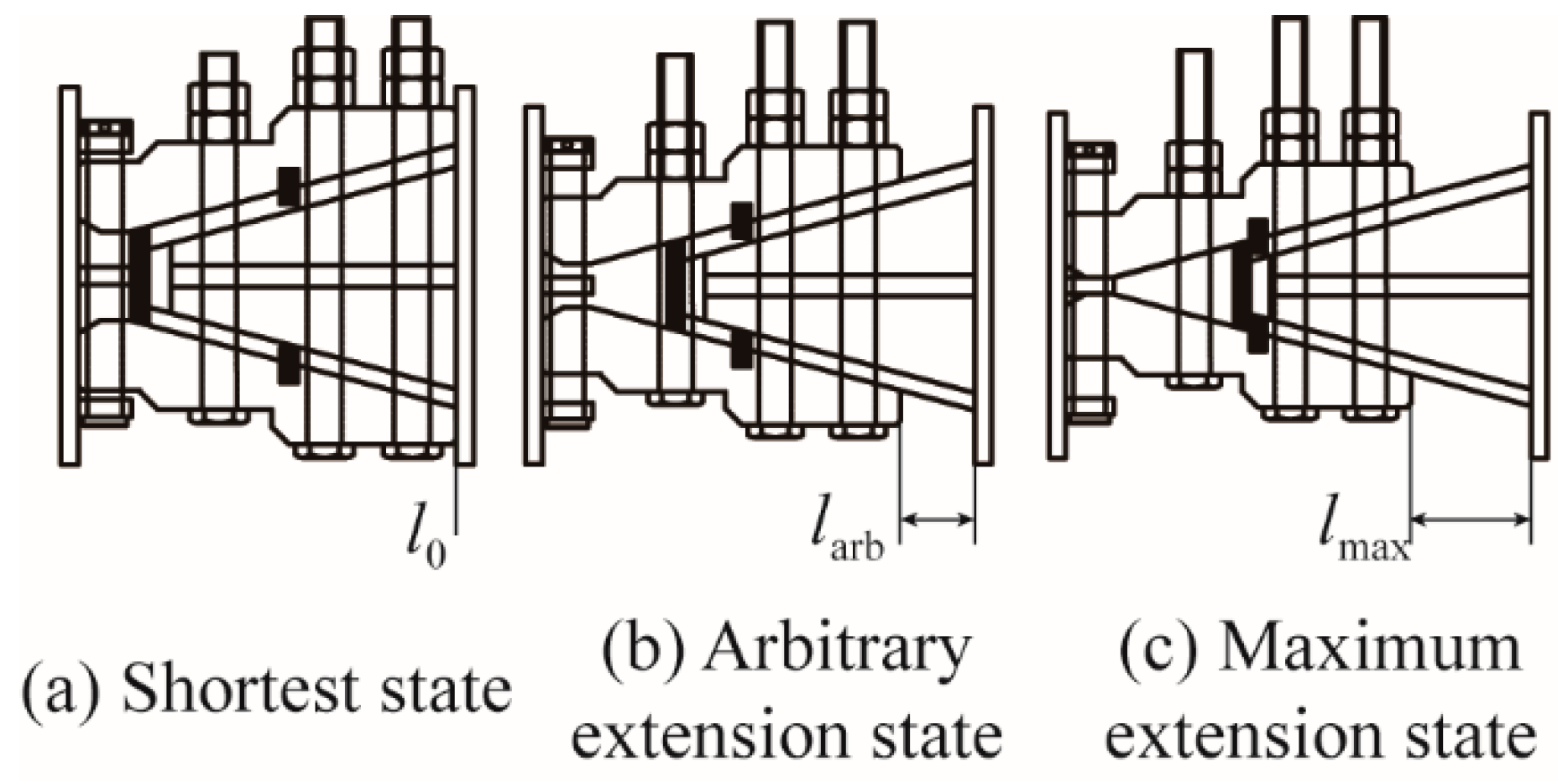
2.1. Basic Function of Active Joints

There are three main steps to complete the construction process of inner-braced retaining structures, as shown in Figure 1. The first step is to build the retaining piles or retaining walls. Then, excavation is conducted; meanwhile, the inner bracing structures are installed. Finally, the main structures are built and the inner bracing structures are demolished. The total length of steel tube bracing lSI should be smaller than the excavation length lEI such that the steel tubes can be put into the pit. In other words, there is a gap between the steel tube and the retaining structure. Simultaneously, an extra length is needed to fill this gap. An active joint is designed to play the role of this part. This active joint should have a large extension length with the help of a hydraulic jack, which can bring the steel bracing close to the side wall of the foundation pit, and the pre-axial force can be achieved. The steel bracing with the active joint should be able to be stressed separately after the jack as a tool is removed. In addition, the designed active joint should be self-locking without any other spare parts. Furthermore, in the demolition process, the active joint should be able to be shorten in length to eliminate the internal force of the steel bracings and facilitate the demolition of the steel bracings.
The deformation of the retaining piles/walls occurs in the process of excavation such that:
  • Before deformation (installation): lEI—excavation width, lSI—total length of the steel tube, lAI—length of the active joint, and lGI—length of the reserved gap.
  • In deformation (working): lEW—excavation width, lSW—total length of the steel tube, and lAW—length of the active joint.
  • After deformation (demolition): lED—excavation width, lSD—total length of the steel tube, lAD—length of the active joint, and lGD—length of the demolition required gap.

2.2. Components and Composition

The components and composition of the BFW active joint are plotted in Figure 2. The structure pattern of the BFW active joint is symmetrical, and the two symmetry planes are shown with the green and orange dotted lines. The symmetrical structure is favorable for the structure to bear the load evenly. The wedge seat is welded to the end plate, which is connected to the steel tube bracing. The splints, which can slide along the round rods, are connected to a steel base. The base is welded to another end plate, which compress tightly on the purlin. If the BFW active joint is installed on site, a hydraulic jack on the semi-open jack tray will be needed to exert a pre-axial force. When the pre-axial force reaches the intended value, the high-strength bolts will be fastened to push the splints that hold the wedge seat tightly. Then, the hydraulic jack will be unloaded and moved away. From then on, the BFW active joints work as a key joint in the steel bracing system.
Figure 3 shows the different extension states of a BFW active joint. The joint is in the shortest (l0) state before it is installed in site, and it will be in an arbitrary extension (larb) state when it is applying the intended pre-axial force. However, the maximum extension will be limited to the maximum extension (lmax) state, which may usually meet the requirements of exerting the pre-axial force on the basis of the construction practice of braced excavations.
A BFW active joint can be designed according to the diameters of the steel tubes, whose common types are Φ609 mm and Φ800 mm.

2.3. Working Mechanism

The structural design of the BFW active joint is based on the principle of force decomposition under static equilibrium. The force balance triangles show the axial force decomposition and transfer process in Figure 4 (taking one “leg” for analysis, such that the axial force is F/2 on each side). The high-strength bolts bear the tension force decomposed from the resistance between the splints and the wedge seat.
  • F/2: the axial force transferred by the steel tube to each side.
  • T: the tension provided by a high-strength bolt, where n is the number of the bolts on one side, and a BFW active joint contains 2n bolts.
  • R: the resistance between the splints and the wedge seat.
  • V: the supporting force between the splints and the base.
  • f: the friction between the bottom of the splints and the base.
  • δ: the steel friction angle, where μ is the steel static friction coefficient, and tan δ = μ.
  • θ: the angle between the direction of the axial force F/2 and the direction of the contact surface, where the contact surface is between the wedge seat and the splints.
The design bearing capacity N and design stiffness Kd is calculated under the most unfavorable condition. This condition is defined as when the extension length is the maximum extension lmax. According to the code for the design of steel structures [22], the design tensile bearing capacity of bolts Nbt can be calculated as follows [23]:
N bt = 0.8 P ,
where P is the intended pretension value for a high-strength bolt, and R is the resultant force that the axial F produces on the splints such that:
R = F / 4 cos ( 90 θ δ ) .
According to the force of the splints:
R cos ( θ + δ ) = n T + f ,
f = μ F / 4 .
Substituting Equations (2) and (4) into Equation (3):
F = 4 n T tan ( θ + δ ) 1 μ tan ( θ + δ ) ,
where the axial force is converted into a vertical force through the contact surface, which is shared by the bolts:
N 1 μ tan ( θ + δ ) 4 n tan ( θ + δ ) = N bt .
After the transformation:
N = N b t 4 n tan ( θ + δ ) 1 μ tan ( θ + δ ) .
Therefore, the design-bearing capacity N of a BFW active joint can be obtained.
In the design of a BFW active joint, the dimensions of each part shall be determined according to the following criterion:
A min A tube ,
where Atube is the cross-sectional area of the steel tube and Amin is the area of the minimum section of the BFW active joint when under the most unfavorable conditions.
Because the cross-section of a BFW active joint is not uniform, it is hard to calculate the stiffness using an analytical method. A model of a compressed column was established to estimate the stiffness of a BFW active joint as a simplified calculation method, i.e., the compressed column has the same volume and height as the BFW:
i = 1 m V i = A d h ,
where:
  • Vi—the volume of a component of the BFW active joint.
  • Ad—the cross-sectional area of the column.
  • h—the length of the BFW active joint.
  • m—the number of the components of the BFW active joint.
  • i—the component number.
Under normal use, the BFW active joint is generally in the elastic stage, so its design stiffness Kd can be calculated according to Hooke’s law:
K d = F Δ L = E A l = E A d h .

3. Field Operation Tests

3.1. Design of Specimens

In order to test the construction feasibility and applicability of this new style active joint, three BFW active joint specimens were designed and manufactured to conduct the field operation tests. In the manufacturing process, precision casting was implemented to obtain the splints, and welding after cutting was carried out to obtain the other components. The strengths of these BFW active joint specimens were designed on the basis of GB 50017-2017 (2017) [22] and GB T699-2015 (2015) [24]. The design drawing of the BFW active joint is shown in Figure 5.
The design calculation was conducted with the method mentioned in Section 2.3. Furthermore, the parameters were determined with reference to an SW active joint and other new active joints [21,25]: θ was 15° and μ was 0.15, such that the δ was 8.53°; n was 3; based on the engineering situation, the value of lmax was 150 mm; P was 570.4 kN; and the other size parameters are shown in Figure 5. Therefore, substituting the parameters into Equations (1)–(7) and Equations (9) and (10), this gives: Nbt was 456.3 kN, the design bearing capacity N of a BFW active joint was 2551 kN, and the design stiffness Kd was 297 kN/mm.
The design result should satisfy Equation (8) when the specimens are under the most unfavorable processing condition. For a BFW, the most unfavorable processing condition is the maximum extension state, so lmax was 150 mm and Amin was calculated to be 46,219.44 mm2. The Atube of the Φ609 mm × 14 mm steel tube was 26,169.47 mm2 and Atube of the Φ800 mm × 16 mm steel tube was 39,108.14 mm2. They were both smaller than the Amin, therefore Equation (8) was satisfied. Therefore, the design results satisfied the strength-checking calculation.
Three full-size specimens were named BFW-AJ1, BFW-AJ2, and BFW-AJ3. Their photos are shown in Figure 6.

3.2. Test Site and Preparation

The test site was located in the foundation pit of Heizhuanghu Station on the East Extension Line of Line-7 of Beijing Subway. The geological conditions and supporting system of the foundation pit are shown in Figure 7.
According to the design of the supporting system, the design axial force of the steel tube was 2480 kN, which was smaller than the design bearing capacity of a BFW active joint (2551 kN). Therefore, the BFW active joint met the design requirements of the bracing system, and it could be used instead of the SW one in a field operation test.
The BFW active joint specimens needed to be pre-processed at the test site before their installation into the bracing system. The end plate near the wedge seat needed to be welded with a short steel tube concentrically and tightly; then, the other side of the short steel tube was connected with a standard steel tube though a flange. The BFW active joints needed to be at a minimum length state and the bolts needed to be fastened. After the pre-process, the steel tube with the BFW active joint was installed into the foundation pit as a bracing.

3.3. Operation Process
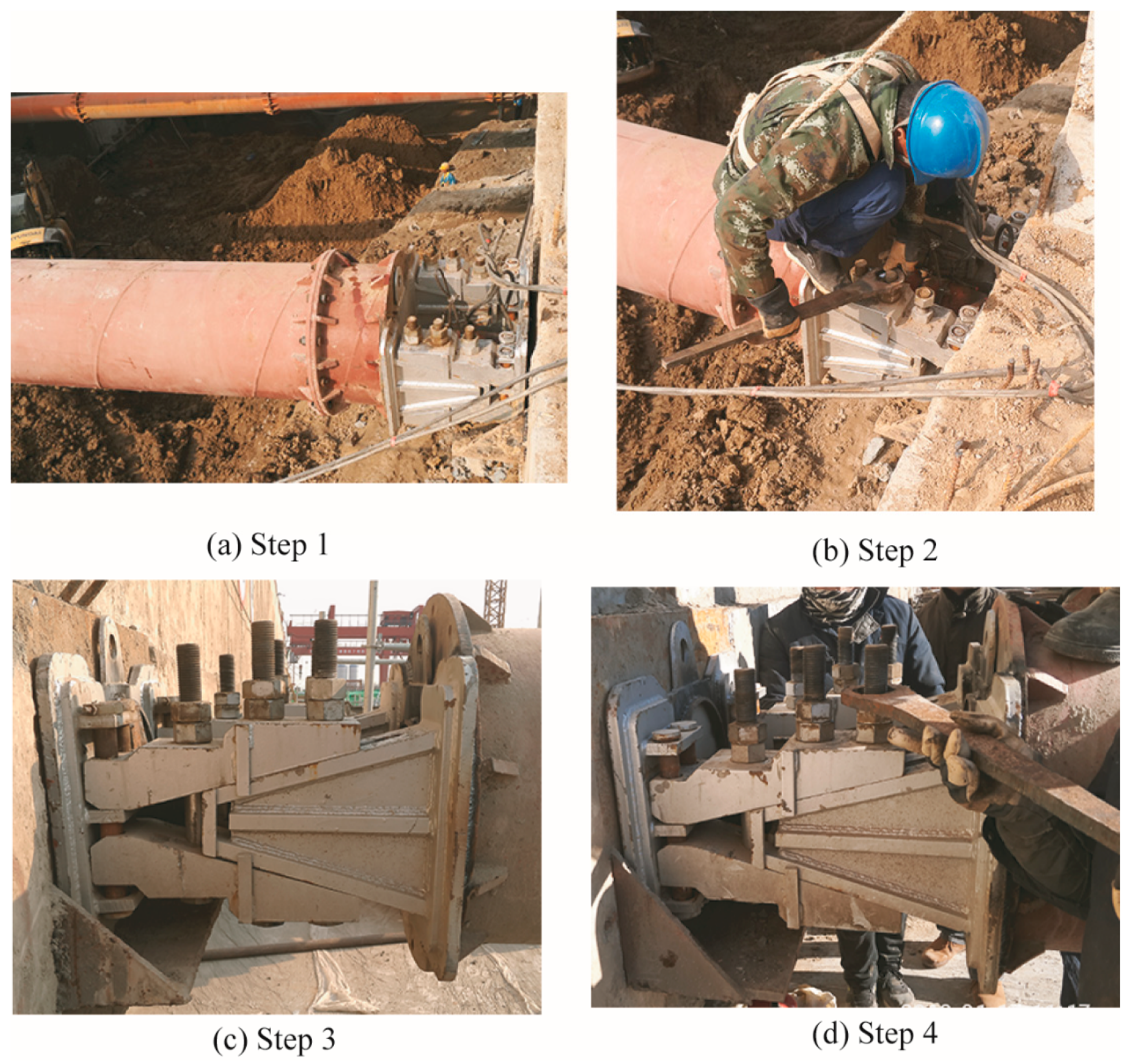
The steps of the installation and demolition of the steel tube bracing with the BFW active joint were as follows:
(1)
The gap was filled with fillers like steel wedges or cement, as shown in Figure 8a. It should be noted that the end plate near the splints must be kept parallel to the vertical plate of the buried tray. If there exists an angle between the two plates, it is necessary to fill the gap with fillers like steel wedges or cement.
(2)
The bolts were tightened step-by-step in the process of the jack force application, as shown in Figure 8b. The jack force application consists of three loading stages using a jack pressure gauge, i.e., 5 MPa, 12 MPa, and 25 MPa. Six bolts were fastened one-by-one on each stage. The jack force application was stopped when the loading using the jack pressure gauge reached 25 MPa which met the intended pre-axial force. All the bolts should be fastened at the same level, and the fastened torque should be 4111 Nm. No space should be left between the wedge seat and the splints.
(3)
The jack was unloaded and moved away, as shown in Figure 8c, and the BFW active joint started working. The earth pressure transmitted by the lateral walls of the foundation pit were borne by the steel tube bracings with the BFW active joints. The BFW active joints were connected with steel tubes in a series connection and they bore the same axial force as the steel tubes.
(4)
The steel tube bracing with the BFW active joint was demolished. The bolts were loosened after the axial force was applied by the jack, as shown in Figure 8d. Then, the BFW active joints were shortened and they were moved out of the pit with the steel tube bracings.

3.4. Analysis of the Field Operation Results

The field operation tests of the three BFW active joint specimens were successfully completed and the construction feasibility the joints was effectively verified. The BFW active joints can be conveniently designed to match different types of steel tube bracings. Furthermore, some technical points have been obtained from the field operation tests as follows:
(a)
It is important to weld the BFW active joint concentrically with the short steel tube in the pre-processing at the test site.
(b)
The total length of the BFW active joint and steel tube is a little smaller than the excavated width of the foundation pit, so a gap of 30–130 mm will be formed. At this time, since the BFW active joint is in the zero-extension state, it can be extended to eliminate the gap during jack force application.
(c)
It is necessary to keep the contact surface of the purlin or the diaphragm retaining walls flat and vertical.
(d)
It is important to ensure that the loading process is uniform and slow, and that the bolts are tightened to the same tightening torque (4111 Nm for the M39 type). Both the whole loading process and tightening process should be divided into three steps, step-by-step, which can provide a good loading effect. The bolts need to finally be fastened to a tightening torque of 4111 Nm.
(e)
The jack is used to supplement the axial force and then the bolts will be tightened according to the above steps once the axial force loss occurs with the variation of soil excavation and earth pressure change.

4. Laboratory Axial Compression Experiments

The construction feasibility of the BFW active joints was verified by the abovementioned field operation experiments. In order to investigate their mechanical behavior, laboratory axial compression experiments were conducted to obtain the ultimate bearing capacity and failure modes. BFW-AJ1 and BFW-AJ2 remained in good condition after field operation tests; therefore, they were taken to the laboratory for axial compression experiments.

4.1. Measurement Scheme of Displacements and Strains

Displacements and strains were monitored for the two BFW active joints during the loading procedure. Each side of BFW-AJ1 and BFW-AJ2 was placed with one sensor between the end plates to measure the overall axial deformation. One side was named DN and the other side was named DS, as shown in Figure 9a. Some strain gauges were installed in certain key positions to measure strain changes, shown as SNB1–SNB3, SSB1–SSB3, SN1–SN10, and SS1–SS10. Taking one specimen as an example, six strain gauges (SNB1–SNB3, SSB1–SSB3) were installed on the high-strength bolts in the direction of the bolt axis, and each bolt got one, as shown in Figure 9b; 20 strain gauges (SN1–SN10, SS1–SS10) were installed on the outer surface of two sides, and each side got 10, as shown in Figure 9c,d. Before sticking the strain gauge on, the surface of the bolts were properly polished.

4.2. Loading Schemes

As mentioned above, the maximum extension length of this BFW active joint was 150 mm. Its stiffness in this condition was the smallest. The laboratory axial compression experiments were conducted using a test loading device (4000-t multifunction structural test loader, POPWIL electrical and mechanical control engineering Co., Ltd., Hangzhou, Zhejiang, China). Displacements and strains were collected using a matching acquisition system. Two loading stages were performed as follows:
(a)
The specimens were loaded from 0 kN to 500 kN and unloaded back to 0 kN, where the loading rate was 30 kN/min. Gaps in the specimens could be closed in this stage of preloading.
(b)
Formal loading and data collection were applied under force control, where the loading rate was 50 kN/min. The loading started from 0 kN. When the bearing capacity of the specimens could no longer rise or had a large deformation or failure, loading was stopped. Then, unloading was slowed down and the test ended.

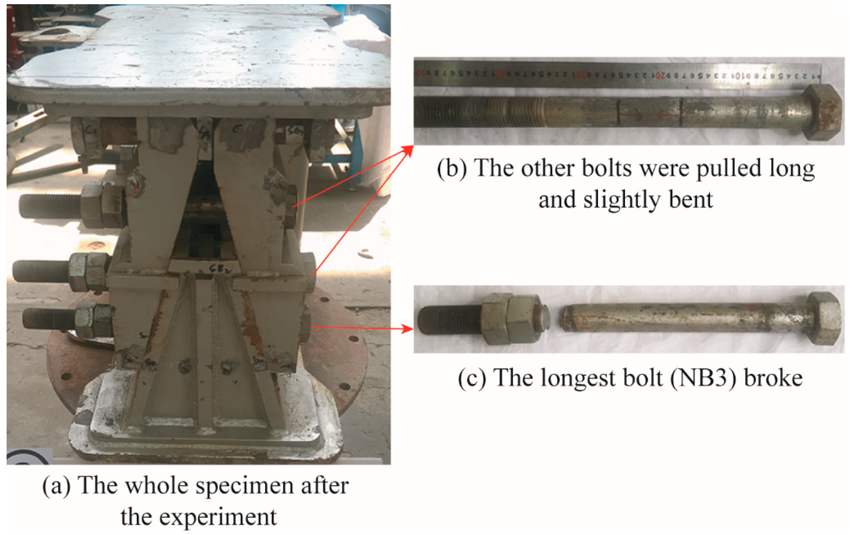
4.3. Experimental Phenomena and Failure Modes

When the loading reached about 4021 kN, BFW-AJ1 collapsed and the NB3 bolt broke. The failure loading of BFW-AJ2 was 4195 kN.
The loading pressure of the loading device dropped suddenly with a loud noise, which was caused by the breaking of the NB3 bolts. At this time, the specimens were regarded as failures, and the loading process ended. The failure phenomena of the two specimens gradually appeared when the loading range was from 4000 kN to 4200 kN. Due to their size and type, test conditions and loading schemes of two specimens were the same, the failure modes were almost the same as shown in Figure 10. The high-strength bolt (NB3) was broken at the position of the nut inner side. The breaking of the bolt was a brittle fracture due to the material property of the high-strength bolts. Furthermore, the remaining five high-strength bolts were pulled slightly longer than the initial state in the axial direction and slightly bent. Both of the specimens broke at the same position and in the same mode; therefore, the results were repeatable.

4.4. Bearing Capacities and Stiffness

The bearing capacities and the stiffness of the two specimens were obtained from the load–displacement curves, as shown in Figure 11. For both BFW-AJ1 and BFW-AJ2, the overall displacement on the north side was larger than that on the south side. That results showed that a little eccentric loading existed in the loading device itself and the loading center deviated to the north side. Because the lengths of the NB3 and SB3 bolts were longer than those of the other bolts and were affected by the eccentric loadings, the NB3 bolts were the first one to be pulled apart. In addition, the development trends of the four curves were basically the same, as shown by the load–displacement situations of BFW-AJ1 and BFW-AJ2 being very similar. With similar curves and failure modes, the mechanical properties of BFW active joints were shown to be repeatable, reliable, and remained in a stable state.
During the loading procedure, the load–displacement curves of these BFW active joint specimens gradually developed from straight lines to curves: at the beginning of the loading procedure, the load–displacement curves presented elastic behavior; when the loading of BFW-AJ1 reached 2625 kN and the loading of BFW-AJ2 reached 3065 kN, the specimens changed from the elastic phase to the plastic phase in the axial direction; and when the loading of BFW-AJ1 reached 4021 kN and the loading of BFW-AJ2 reached 4195 kN, the curves terminated, which meant the NB3 bolts were pulled apart. Due to the brittle fracture of high-strength bolts, the load-displacement curve of the specimen does not show a falling section, so the yield-failure mode of low carbon steel cannot be completely copied.
In the engineering field, the large plastic deformation of the components is generally not allowed and there is no obvious yield phase of the two specimens. Therefore, the conditional yield strength was determined according to the load–displacement curves. The standard strength (yield strength) of a BFW active joint (M39 type) was determined to be 3164 kN according to the average value of the four curves, and the partial safety factor of resistance was 1.175, such that the test design bearing capacity was 2693 kN [23]. The test stiffness of a BFW active joint was 325 kN/mm by taking the average value of the elastic segment of the curves. The calculated design bearing capacity was 2551 kN and the deviation between the calculated value and the test value was 5.27%; the calculated design stiffness was 297 kN/mm and the deviation between the calculated value and the test value was 8.62%. These deviations are small, thus the reliability of the calculation method was verified. The summary of the test results of the two specimens is shown in Table 1.

4.5. Strain Distributions

Figure 12 shows the variations of the axial strains of the six high-strength bolts of the BFW-AJ1 and BFW-AJ2 specimens.
The high-strength bolts were designed as the core stress members; therefore, they bore the axial force, which was converted through the contact surface. In general, the bolts appeared to display excellent load-deformation characteristics. At the beginning of the loading process, the curves were nearly straight lines and the bolts were in the elastic deformation stage. As the loading increased, the curves entered the nonlinear stage and the bolts exceeded the elastic deformation. Further, as the loading increased, the strain increased more significantly. Furthermore, the curves of the same type of bolts are compared in a same diagram. It can be evidently observed that the curves were close to each other, especially at the elastic deformation stage, such that the results of the mechanical experiments of the bolts could be repeated, which met the design expectations. Therefore, the tensile strength of the bolts determined the overall strength of the BFW active joint within a certain range. In addition, since the pressure of the loading device on the two sides was not uniform, there was a slight eccentric compression phenomenon, where the curves on both sides were not exactly the same. The slight eccentric compression phenomenon may also occur during actual engineering, but the bolts and the whole specimens will not be affected too much. Consequently, the results showed that the BFW active joint had a good adaptability to the uneven loading within a normal range.
Figure 13 shows the variations of the strains of the key positions of the BFW-AJ1 and BFW-AJ2 specimens.
It was found that the overall mechanical properties of a BFW active joint were repeatable and the load–strain curves at the key positions were almost the same, especially in Figure 13b,d,e. The curves of SN1–SN10 and SS1–SS10 indicated that the specimens gradually entered the inelastic deformation stage from the elastic deformation stage, then they underwent plastic deformation until their compression and bending failure occurred. The deformation of the main body of the specimens was smaller than that of the bolts, and the stiffness of the main body of the specimens was larger than that of the bolts. However, the degree of deformation of different parts on the main body was not the same, i.e., the positions of SN1–SN2, SN7–SN10, SS1–SS2, and SS7–SS10 had a greater deformation than the positions of SN3–SN6 and SS3–SS6. Therefore, within the structure, the effect of the axial force was greater than that of the bending moment, and the deformation results provided guidance for optimizing the design scheme. Furthermore, from Figure 13a–c, it was found that the strain of some curves appeared in the opposite direction of the whole trend at a certain stage, then moved back to the whole trend, and even appeared to be almost symmetrical curves in Figure 13c. This phenomenon also proved that the loading device had an eccentric compression; the compression of the two sides was not consistent; and in the direction of the bolts’ axis, there was also a small eccentric compression. As the pressure increased, the eccentric compression of some positions recovered. The eccentric compression in some positions continued to develop due to the structural characteristics, but the overall deformation was in the normal range. Therefore, the load–strain curves at the key positions also proved that the BFW active joint showed a good compression performance and eccentricity resistance.

5. Numerical Simulation and Validation

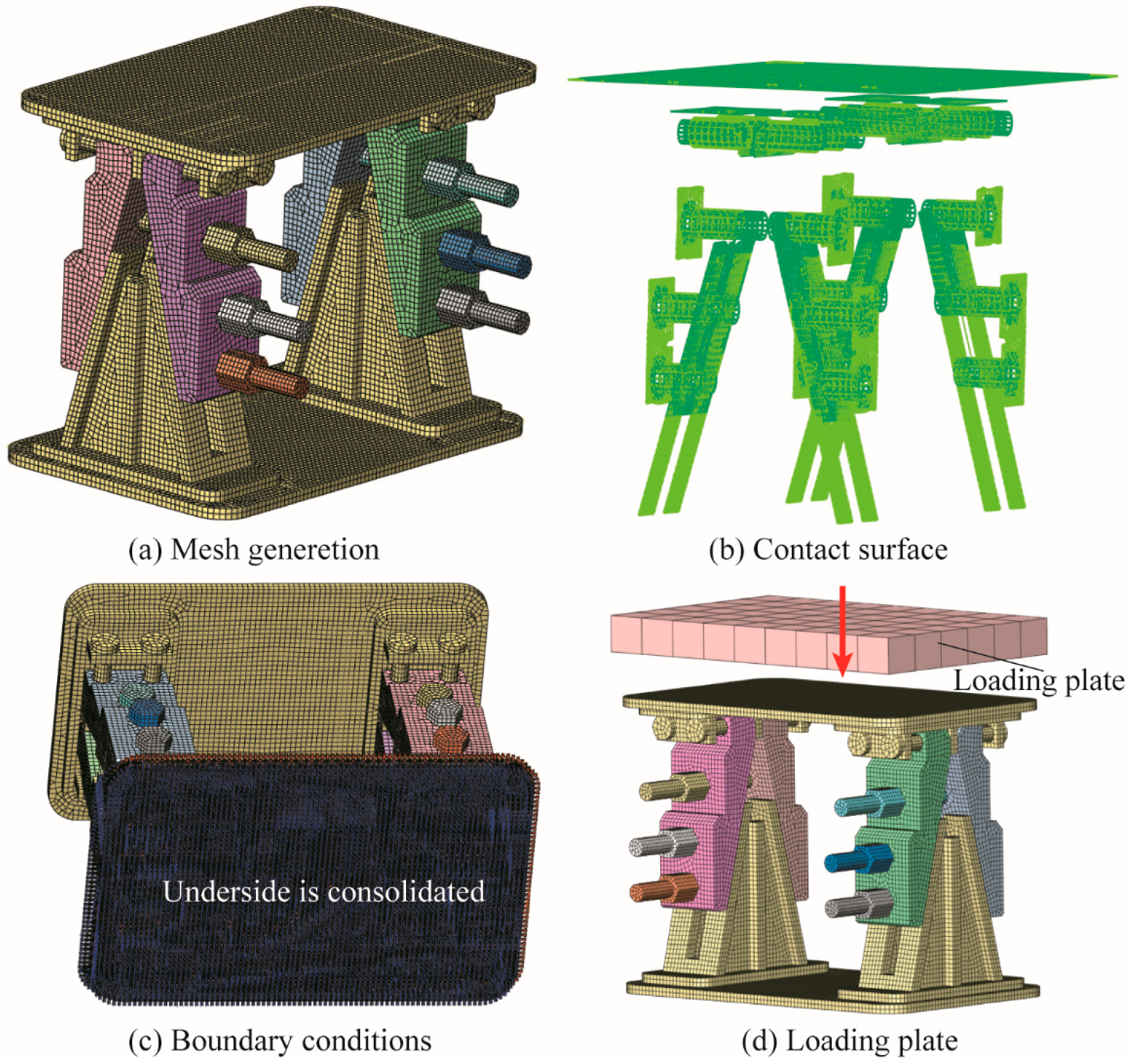
5.1. Numerical Model

A series of numerical simulations were conducted using the finite element software MIDAS FEA (3.7.0, MIDAS Information Technology Co., Ltd., Seoul, South Korea) for further investigation of the compression bearing capacity and the stiffness of the BFW active joints. The geometrical dimensions of all the numerical model components were the same as those of the BFW active joint specimens. Furthermore, in the model, different welded steel plates were combined into one component because the welds and the steel plates had the same strength and the welds would not crack under the axial compressive force [15,26,27,28]. The numerical simulation was extremely sensitive to the selection of the element type and mesh generation [16]. As there were many surface-to-surface contact interactions in the numerical model and the nonlinear material properties were taken into consideration, a suitable element type would need to be selected for the numerical model to obtain reliable results. All the components of the BFW active joint were mainly meshed using hexahedron solid elements, as shown in Figure 14. The bolts and the contact surfaces, which were the key parts, were meshed using the small size elements to improve the accuracy of the calculation. The element size ranged from 3 mm to 8 mm.
A nonlinear analysis was performed in the numerical model by taking both the material and geometric nonlinearities into consideration. The material parameters are shown in Table 2. The loading plate was modeled as rigid elements with a large Young’s modulus of E = 2.06 × 10⁸ N/mm2. Because the BFW active joint was assembled using multiple components, there were multiple contact surfaces among the different components. The setup of the contact pairs in the numerical model are listed in Table 3. Most of contact pairs were simulated using a surface-to-surface contact method called a axisymmetric general contact. In this condition, the two objects in the space can be in contact with each other but not through each other, and the two contact surfaces can be separated and contacted. A stiffness coefficient of 1 represents hard contact. The tangent friction force was applied through a penalty method, and according to the handbook of mechanical design [25], the friction coefficient was 0.15. The boundary condition was set up to consolidate the bottom surface of the lower end plate. The loading form was simulated by the loading plate, just like the loading of the laboratory press. A vertical loading was loaded on the surface center of the loading plate, and the automatic-loading-step number was selected in the software to improve the calculation efficiency. Finally, the ultimate loading of the experiment, i.e., 4195 kN, was uniformly loaded in seven steps.

5.2. Comparisons of Numerical and Experimental Results

5.2.1. Failure Modes

The comparisons of the failure modes of the BFW active joint are shown in Figure 15. The results of the numerical analysis were consistent with those of the test. First, the longest bolts, the NB3 bolt and SB3 bolt, were stretched a lot, and according to the material condition of a 10.9-class, high-strength bolt, fracture had already occurred. Six high-strength bolts were mainly subjected to tensile deformation, where the amount of plastic deformation was greater than that of other parts. Second, due to the folding-line structure of the splints, a certain rotation of the splints occurred after compression, such that the bolt shanks were bent by the bolt holes in the splints. Therefore, the bolts not only had an axial tensile deformation but also a bending deformation. The above two failure modes were presented by the numerical simulation.
Using the comparisons, further optimization could be carried out in in terms of the ductility and model class of the bolts.

5.2.2. Load–Displacement Curves

The comparisons of the load–displacement curves of the BFW active joint are shown in Figure 16, where it can be seen that the curves obtained numerically and experimentally were extremely similar over the whole range.
In the initial stage, the numerical simulation results in the elastic range were very close to the experimental ones. From 0 kN to 2500 kN, the maximum deviation, minimum deviation, and average deviation between the numerical result curve and the BFW-AJ2 DS curve were 16.70%, 3.74%, and 10.22%, respectively. The deformation of the numerical model was smaller than that of the BFW-AJ2 DS. In the second half of the plastic section, there was still a certain deviation, but the deviation was not large. The numerical result curve was more similar to the BFW-AJ2 DN curve. From 2500 kN to 4000 kN, the maximum deviation, minimum deviation, and average deviation between the numerical result curve and the BFW-AJ2 DN curve were 30.01%, 7.08%, and 18.54%, respectively. The deformation of the numerical model gradually became larger than that of the BFW-AJ2 DN. The numerical curve was generally among the four test curves. Therefore, more material nonlinearity factors should be considered in further simulations.

5.2.3. Load–Strain Curves

The load–strain curves of the bolts found using numerical simulations were compared with those found using experiments, as shown in Figure 17. The results of the numerical simulation and the experiments were in good agreement with each other. In order to highlight the core stress component, a comparisons between the high-strength bolts’ curves was undertaken.
In the initial stage, the numerical simulation results in the elastic range were very close to the experimental ones. From 0 kN to 2500 kN, the maximum deviation, minimum deviation, and average deviation between the numerical result curve FEM SB1 and the test curve BFW AJ1 SSB1 were 27.20%, 16.10%, and 21.65%, respectively; the three deviations between the numerical result curve FEM SB2 and the test curve BFW AJ2 SSB2 were 25.21%, 7.12%, and 16.16%, respectively; and the three deviations between the numerical result curve FEM SB3 and the test curve BFW AJ2 SSB3 were 17.54%, 13.46%, and 15.50%, respectively.
In the plastic section, from 2500 kN to 4000 kN, the maximum deviation, minimum deviation, and average deviation between the numerical result curve FEM SB1 and the test curve BFW AJ1 SSB1 were 23.23%, 14.00%, and 18.62%, respectively; the three deviations between the numerical result curve FEM SB2 and the test curve BFW AJ1 SNB2 were 25.47%, 8.11%, and 16.79%, respectively; and the three deviations between the numerical result curve FEM SB3 and the test curve BFW AJ2 SSB3 were 14.59%, 2.60%, and 8.60%, respectively. The deviation values showed that the curves simulated using the numerical model were in good agreement with the experimental results, whether using bolt 1, bolt 2, or bolt 3. The numerical simulation results basically accorded with the changing trend of the bolt strain. Therefore, in the subsequent optimization design, the numerical model can be used for fine adjustment and improvement in order to predict the results accurately and save the cost of experimentation.

6. Conclusions

The field operation tests of the BFW active joints showed that they could be installed and dismantled easily and quickly at the construction site and may have a good construction feasibility and a wide applicability. In addition, the axial force could be supplemented during work by the Jack once the axial force loss occurs.
The laboratory axial compression experiments of the BFW active joints showed that they had outstanding mechanical properties, good compression performance, and eccentricity resistance. The experiments obtained a yield strength, design bearing capacity, and stiffness of the BFW active joints of 3164 kN, 2693 kN, and 325 kN/mm, respectively. The calculated design-bearing capacity was 2551 kN, and the calculated design stiffness was 297 kN/mm. The experimental results verified the reliability of the calculation method.
The numerical simulation results were in good agreement with the experimental ones in terms of the failure modes, load–displacement curves, and load–strain curves. The numerical model could effectively predict the mechanical properties of a BFW active joint, and may provide support for further optimization.
In conclusion, the BFW active joint has the advantages of high-quality structural and mechanical properties, and is suitable for popularization and application.

Author Contributions

M.Z. designed the new joint and conceived the studying route; M.Y. conducted all experiments, analyzed the results, and wrote the manuscript; P.L. revised the manuscript and improved the language writing; and Y.G. checked the manuscript and made some modifications. All authors have read and agreed to the published version of the manuscript.

Funding

This work was partially supported by the National Natural Science Foundation of China under Grant No. 51538001, 51738010, and 51978018.

Acknowledgments

We would like to thank the anonymous reviewers for their careful reading and useful comments that helped us to improve the final version of this paper.

Conflicts of Interest

The authors declare that there are no conflict of interest.

References

  1. Tan, Y.; Li, M. Measured performance of a 26 m deep top-down excavation in downtown Shanghai. Can. Geotech. J. 2011, 48, 704–719. [Google Scholar] [CrossRef]
  2. Zhang, M.; Yang, M.; Li, P.; Lu, D. An innovative bolt fastener for steel tube bracing in deep excavations. In Proceedings of the China-Europe Conference on Geotechnical Engineering, Vienna, Austria, 13–16 August 2018. [Google Scholar]
  3. El-Sawy, K.M. Inelastic stability of liners of cylindrical conduits with local imperfection under external pressure. Tunn. Undergr. Space Technol. 2013, 33, 98–110. [Google Scholar] [CrossRef]
  4. Feng, R.; Lin, J.; Mou, X. Experiments on hybrid tubular K-joints with circular braces and square chord in stainless steel. Eng. Struct. 2019, 190, 52–65. [Google Scholar] [CrossRef]
  5. Lam, E.S.S.; Li, B.; Xue, Z.H.; Leung, K.T.; Lam, J.Y.K. Experimental studies on reinforced concrete interior beam-column joints strengthened by unsymmetrical chamfers. Eng. Struct. 2019, 191, 575–582. [Google Scholar] [CrossRef]
  6. Puzrin, A.M.; Alonso, E.E.; Pinyol, N.M. Braced excavation collapse: Nicoll Highway, Singapore. In Geomechanics of Failures; Springer: Dordrecht, The Netherlands, 2010; pp. 151–181. [Google Scholar]
  7. Endicott, J. Lessons learned from the collapse of the Nicoll Highway in Singapore April 2004; IABSE Symposium Report; International Association for Bridge and Structural Engineering: Zurich, Switzerland, 2013; Volume 101, pp. 1–6. [Google Scholar]
  8. Li, H.; Wang, G. Causes and suggestion on deep foundation excavation accident in some. Constr. Technol. 2010, 39, 57. [Google Scholar]
  9. Zhang, K.; Li, J. Accident analysis for “08.11.15” foundation pit collapse of Xianghu station of Hangzhou metro. Chin. J. Geotech. Eng. 2010, 32, 338–342. [Google Scholar]
  10. Costa, R.; Valdez, J.; Oliveira, S.; da Silva, L.S.; Bayo, E. Experimental behaviour of 3D end-plate beam-to-column bolted steel joints. Eng. Struct. 2019, 188, 277–289. [Google Scholar] [CrossRef]
  11. Gil-Martín, L.M.; Hernández-Montes, E.; Shin, M.; Aschheim, M. Developments in excavation bracing systems. Tunn. Undergr. Space Technol. 2012, 31, 107–116. [Google Scholar] [CrossRef]
  12. Ataei, A.; Bradford, M.A.; Valipour, H.R.; Liu, X. Experimental study of sustainable high strength steel flush end plate beam-to-column composite joints with deconstructable bolted shear connectors. Eng. Struct. 2016, 123, 124–140. [Google Scholar] [CrossRef]
  13. Grimsmo, E.L.; Clausen, A.H.; Langseth, M.; Aalberg, A. An experimental study of static and dynamic behaviour of bolted end-plate joints of steel. Int. J. Impact Eng. 2015, 85, 132–145. [Google Scholar] [CrossRef] [Green Version]
  14. Iwicki, P.; Wójcik, M.; Tejchman, J. Failure of cylindrical steel silos composed of corrugated sheets and columns and repair methods using a sensitivity analysis. Eng. Fail. Anal. 2011, 18, 2064–2083. [Google Scholar] [CrossRef]
  15. Peng, L.; Guo, X.; Huang, Z.; Xiong, Z.; Yang, S. Experimental studies on behaviour of bolted ball-cylinder joints under axial force. Steel Compos. Struct. 2016, 21, 137–156. [Google Scholar]
  16. Guo, X.; Huang, Z.; Xiong, Z.; Yang, S.; Peng, L. Numerical studies on behaviour of bolted ball-cylinder joint under axial force. Steel Compos. Struct. 2016, 20, 1323–1343. [Google Scholar] [CrossRef]
  17. Zeng, Q.; Guo, X.; Huang, Z.; Zong, S. Uniaxial compression bearing capacity of bolted ball-cylinder joint. Eng. Struct. 2019, 183, 976–986. [Google Scholar] [CrossRef]
  18. Guo, X.; Xiong, Z.; Luo, Y.; Qiu, L.; Liu, J. Experimental investigation on the semi-rigid behaviour of aluminium alloy gusset joints. Thin Walled Struct. 2015, 87, 30–40. [Google Scholar] [CrossRef]
  19. Wang, S.; Zhang, Y.; L, J. Field test verification of new flexible head steel support and deep foundation excavation support effect. Constr. Technol. 2019, 48, 72–77. [Google Scholar]
  20. Zhang, M.; Xie, Z.; Liu, Y. Mechanical properties and improvement measures of the active node in steel braced foundation pit engineering for subway. J. Beijing Jiaotong Univ. 2019, 43, 66–73. [Google Scholar]
  21. Zhang, M.; Yang, M.; Wang, X. Innovative study on active node of steel tube bracing system for braced excavations. Eng. Mech. 2018, 35, 88–94. [Google Scholar]
  22. Editorial Group. GB 50017-2017, Code for Design of Steel Structures; Ministry of Housing and Urbanrural Development of the People’s Republic of China: Beijing, China; General Administration of Quality Supervision, Inspection and Quarantine of the People’s Republic of China: Beijing, China, 2017.
  23. Zhang, M.; Yang, M.; Li, P. Field application and experimental verification of dismountable double-section BFW active nodes for braced excavations. In Proceedings of the 13th Chinese National Conference on Soil Mechanics and Geotechnical Engineering (CNCSMGE), Tianjin, China, 18–21 July 2019; Volume 2, pp. 437–446. [Google Scholar]
  24. Editorial Group. GB T699-2015, Quality Carbon Structure Steels; General Administration of Quality Supervision, Inspection and Quarantine of the People’s Republic of China: Beijing, China; Standardization Administration of the People’s Republic of China: Beijing, China, 2015.
  25. Cheng, D. Handbook of Mechanical Design; Chemical Industry Press: Beijing, China, 2016. [Google Scholar]
  26. Sultan, A.; John, P.; Nikolaos, N. Time-dependent behaviour of cracked, partially bonded reinforced concrete beams under repeated and sustained loads. Eng. Struct. 2018, 163, 267–280. [Google Scholar]
  27. Li, P.; Zou, H.; Wang, F.; Xiong, H. An analytical mechanism of limit support pressure on cutting face for deep tunnels in the sand. Comput. Geotech. 2020, 119, 103372. [Google Scholar] [CrossRef]
  28. Zhang, M.; Li, S.; Li, P. Numerical analysis of ground displacement and segmental stress and influence of yaw excavation loadings for a curved shield tunnel. Comput. Geotech. 2020, 118, 103325. [Google Scholar] [CrossRef]
Figure 1. Construction processes of inner bracing excavation.
Symmetry 12 00140 g001
Figure 2. Components and composition of a bolt fasten wedge (BFW) active joint.
Symmetry 12 00140 g002
Figure 3. The different extension states of a BFW active joint.
Symmetry 12 00140 g003
Figure 4. The axial force decomposition and transfer process.
Symmetry 12 00140 g004
Figure 5. Design drawing of the BFW active joint.
Symmetry 12 00140 g005
Figure 6. BFW active joint specimens.
Symmetry 12 00140 g006
Figure 7. Geological conditions and supporting system of the foundation pit.
Symmetry 12 00140 g007
Figure 8. Field installation and demolition operation process of a BFW active joint.
Symmetry 12 00140 g008
Figure 9. Position of the displacement and strain measuring points.
Symmetry 12 00140 g009
Figure 10. Main failure modes.
Symmetry 12 00140 g010
Figure 11. Load–displacement curves of the specimens.
Symmetry 12 00140 g011
Figure 12. Load–strain curves of the high-strength bolts.
Symmetry 12 00140 g012
Figure 13. Load-strain curves of key positions.
Symmetry 12 00140 g013
Figure 14. Numerical model of the BFW active joint.
Symmetry 12 00140 g014
Figure 15. Comparisons on the failure modes.
Symmetry 12 00140 g015
Figure 16. Comparisons of the load–displacement curves. FEM: finite element model.
Symmetry 12 00140 g016
Figure 17. Comparisons of the load–strain curves of the bolts.
Symmetry 12 00140 g017
Table 1. Summary of the bearing capacity and stiffness.
SpecimenBCmax of EP (kN)Δe (mm)BCult (kN)Δu (mm)YScon (kN)Stiffness (kN/mm)
BFW-AJ126258.87402126.762952295.9
BFW-AJ230658.67419517.573376353.5
BCmax of EP is the maximum bearing capacity in the elastic phase, Δe is the displacement in the elastic phase, BCult is the ultimate bearing capacity, Δu is the ultimate displacement, YScon is the conditional yield strength, and stiffness is the whole specimen’s axial stiffness in the elastic phase.
Table 2. Material parameters of the numerical model.
High-Strength BoltsOther Components
Young’s modulus E2.06 × 105 N/mm22.06 × 105 N/mm2
Gravimetric density7.70 × 10−5 N/mm37.70 × 10−5 N/mm3
Poisson ratio ν0.30.3
Constitutive modelvon Misesvon Mises
Initial yield stress fy355 N/mm2900 N/mm2
Ultimate yield stress fu600 N/mm21080 N/mm2
Table 3. Setup of the contact pairs.
No.Master Surface to Slave SurfaceType
1Wedge seat to splintsSurface-to-surface
2Splints’ heels to baseSurface-to-surface
3Splints to boltsSurface-to-surface
4Splints to polish round rodsSurface-to-surface
5Base to polish round rodsSurface-to-surface
6Loading plate to end plateSurface-to-surface

