Article

Power Beacon-Assisted Energy Harvesting Wireless Physical Layer Cooperative Relaying Networks: Performance Analysis

1
Faculty of Electronics Technology, Industrial University of Ho Chi Minh City, Ho Chi Minh City 700000, Vietnam
2
Power System Optimization Research Group, Faculty of Electrical and Electronics Engineering, Ton Duc Thang University, Ho Chi Minh City 700000, Vietnam
3
Faculty of Electrical and Electronics Engineering, Ton Duc Thang University, Ho Chi Minh City 700000, Vietnam
4
Faculty of Engineering and Technology, Van Hien University, 665-667-669 Dien Bien Phu, Ho Chi Minh City 700000, Vietnam
*
Author to whom correspondence should be addressed.
Symmetry 2020, 12(1), 106; https://doi.org/10.3390/sym12010106
Submission received: 1 December 2019 / Revised: 19 December 2019 / Accepted: 2 January 2020 / Published: 6 January 2020

Abstract

:
In this research, we proposed and investigated the physical layer system called the full-duplex (FD) power beacon-assisted (PB) energy harvesting (EH) relaying cooperative network. The system model has one PB node, one destination (D), one source (S), and one relay (R) node. We investigated the system performance in terms of outage probability (OP) and system throughput (ST) with the power-splitting (PS) protocol in both delay-tolerant (DTT) and delay-limited (DLT) transmission modes. Moreover, the optimal power splitting (PS) factor in both DDT and DLT modes is proposed and derived. Finally, the mathematical closed-form expressions of the OP and ST are derived by using the Monte Carlo simulation with the help of MATLAB software. From the results, it can be observed that the analytical values and simulation values are the same in the effect of the main system parameters.

1. Introduction

When energy harvesting (EH) from green environmental sources, radio frequency (RF) signals can be considered as electrical sources for cooperative network devices. In the comparison of other green environmental electrical sources, the RF signals’ source has excellent advantages, such as small dimensions, low cost, and independence with regard to time and location in urban areas; thus, it is the novel solution for communication devices. In addition, RF signals can provide both information and energy in the communication network nodes through a well-known technique in the communication cooperative network called wireless powered networks (WPNs). From that point of view, WPNs are part of the leading research direction in both academia and industry [1,2,3,4,5]. WPNs have a significant advantage in comparison with the others in many applications and living areas because WPNs do not require the charging, servicing, and maintenance of many battery-powered devices. Instead, battery charging operations can take place through the air without physical cable connections and recharging, replacing the battery. Thus, they are a novel solution for the current and future networks, especially for future applications and technology such as the Internet of Things (IoT) and the Internet of Everything (IoE) [1,2,3,4,5,6,7]. Over the last decade, many studies investigated the system performance of the EH relaying communication network. The paper [8] investigated a wireless-powered cooperative network in which the source cooperates with the hybrid access point (AP) via the relay node. In this paper, the outage probability (OP) and average system throughput (ST) are derived, and the results are validated by the Monte Carlo simulation. In the same direction, the authors in [9] proposed a wireless powered communication network (WPCN) with harvesting energy at the relay that used this energy to transfer information to the destination. In [10], the probability density function (PDF) and cumulative distribution function (CDF) of the cooperative relaying network are proposed and investigated for system performance analysis. The authors in [11] proposed the energy harvesting system with TSR and PSR protocols of a wireless cooperative or sensor network. Then, [12] presented the system performance of a two-way amplify-and-forward (AF) energy harvesting relay network over the Rician fading environment and verified the correctness of the analytical expression by Monte Carlo simulation. Moreover, the authors in [13] proposed the energy harvesting cooperative relaying network with the energy-constrained relay, the source, and the destination under the effect of the co-channel interference. The performance analysis of an energy harvesting relaying cooperative network under a slow fading channel and deriving the closed-form expression of outage probability is focused on, as in [14]. All these researches focus on the cooperative relaying communication network, where the relay nodes harvest energy from the RF signal for transferring the information from the source to the destination nodes.
For enhancing the EH and IT in the cooperative relaying sensor network, some papers proposed the power beacon node (PB) in the cooperative relaying network for transfering the energy to the relay (R) node not only from the source (S) but also from the PB node [15,16,17]. The main point of [15] is investigating the optimal resource allocation in a power beacon-assisted wireless-powered communication network (PB-WPCN). The authors in [16] proposed and investigated the deployment of PBs for powering a cellular network via MPT. [17] investigated an energy-harvesting heterogeneous network (EHHN) with a power beacon (PB). In all the above studies, the authors did not consider the EH relaying network with the presence of the PB node. In addition, the system model was not investigated in the full-duplex in both delay-tolerant and delay-limited transmission modes. From that point of view, this remaining gap can be considered in this research.
In this research, the system performance analysis of the full-duplex (FD) power beacon-assisted (PB) energy-harvesting (EH) relaying cooperative network in the power-splitting (PS) protocol is investigated in both delay-tolerant (DTT) and delay-limited (DLT) transmission modes. After that, we derive the integral closed-form mathematical expressions of the outage probability (OP), the ergodic capacity (EC), and the system throughput (ST). Furthermore, we demonstrate the optimal PS factor of the proposed system. Finally, the analytical mathematical expressions can be verified by using the Monte Carlo simulation. The followings draw some main contributions of this research:
(1) A system model of an FD PB EH relaying sensor network with the PS protocol in DLT and DTT modes are presented.
(2) Closed-form expressions of OT, EC, and ST are derived.
(3) The optimal PS factor of the proposed system is demonstrated for both DTT and DLT modes.
(4) The correctness of the analytical expressions can be verified by using the Monte Carlo simulation.
The rest of this paper can be formulated as followings. The system model is presented in Section 2. The system performance (in terms of the OP and ST) and optimal PS factors are investigated and derived in Section 3. The research results and some discussion are provided in Section 4. Finally, Section 5 concludes the research.

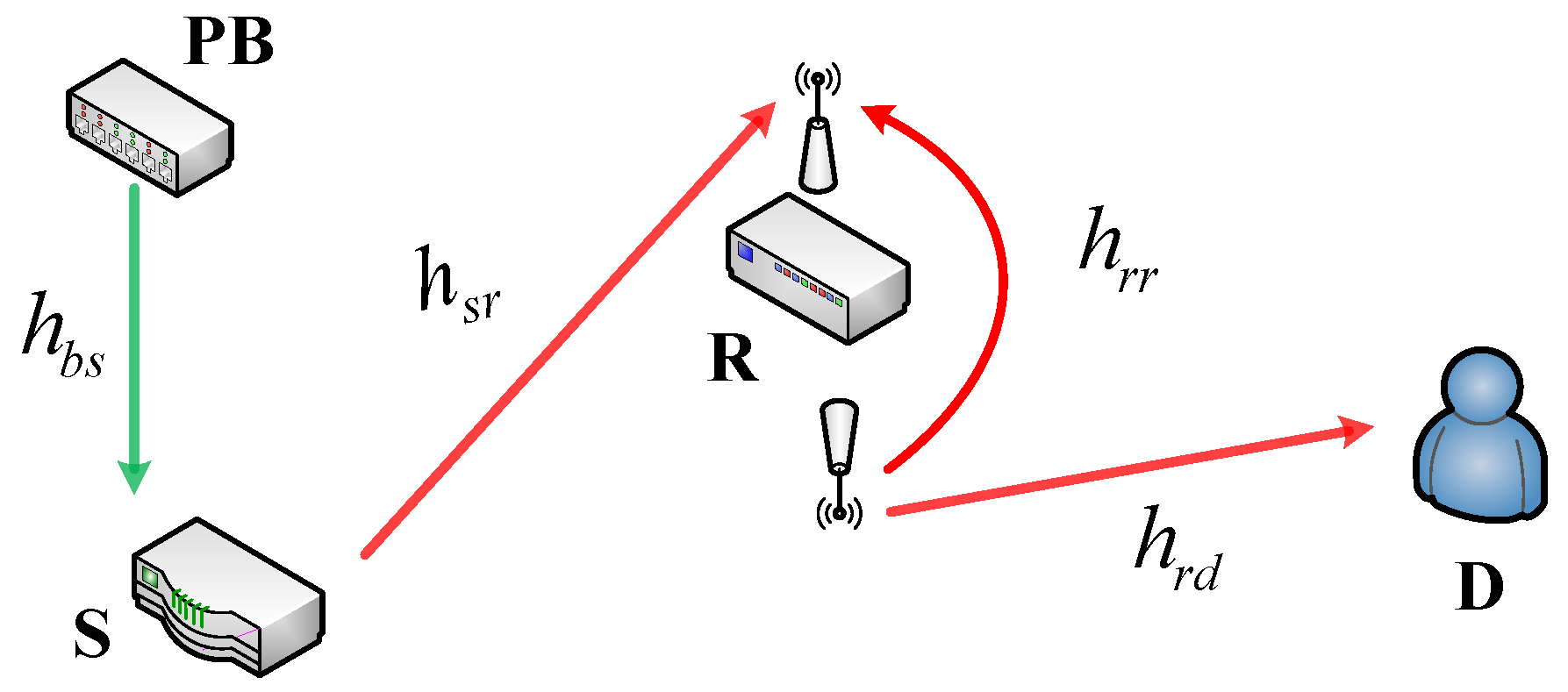
2. Relaying Network Model

In this section, the FD PB EH relaying cooperative network with the PS protocol is drawn in Figure 1. In Figure 1, S transfers the signal to the destination (D) with the help of R, and S receives the energy from PB. In this system model, all the block-fading channels are the Rayleigh fading channels. In this model, we assume that the source is located near the PB, while the distance between the relay and the PB is large enough such that we cannot rely on the energy received from the PB at the relay. In this research, we assume that the system model is working in the PS-based protocol, as displayed in Figure 2. In the first half interval αT time, the PB node transfers energy to the S node, where α is the time-switching factor and 0 < α < 1. In the remaining half-interval time (1 − α)T, the source transfers the energy ρPs to the R and uses the remaining energy (1 − ρ)Ps for the information transmission from the S to the D via the help of R, where 0 < ρ < 1 [18,19].
The received signal at the relay (R) node is expressed as the following equation:
y r = 1 ρ h s r x s + h r r x r + n r .
The received signal at the D node is calculated as
y d = h r d x r + n d .
Then, the harvested energy at the S node from the PB node can be formulated as the following equation
E s = α T η b P B | h b s | 2 .
Then, the average transmits power at the S node can be calculated as
P s = E s ( 1 α ) T = α η b P B | h b s | 2 1 α = k η b P B | h b s | 2
where k = α 1 α .
Then, the harvested energy at R can be calculated by
E r = ( 1 α ) T η s ρ P s | h s r | 2 .
Here, the average transmits power at the relay is formulated as
P r = E r ( 1 α ) T = η s ρ P s | h s r | 2 .
From Equations (4) and (6), we have
P r = η s ρ P s | h s r | 2 = k η s η b ρ P B | h b s | 2 | h s r | 2 .

3. Outage Probability and Throughput Analysis

The signal-to-noise ratio (SNR) at the relay from Equation (1) can be formulated as
γ 1 = E { | s i g n a l | 2 } E { | n o i s e | 2 } = ( 1 ρ ) | h s r | 2 P s | h r r | 2 P r + N 0 .
From Equations (4), (7), and (8), we have
γ 1 = ( 1 ρ ) | h s r | 2 k η b P B | h b s | 2 | h r r | 2 k η s η b ρ P B | h b s | 2 | h s r | 2 + N 0   =   ( 1 ρ ) k η b γ 0 | h s r | 2 | h b s | 2 | h b s | 2 | h s r | 2 | h r r | 2 k η s η b ρ γ 0 + 1
where γ 0 = P B N 0 . We assume that η b = η s = η and denote X = | h s r | 2 | h b s | 2 , Y = | h r r | 2 . Then, the SNR as shown in Equation (9) can be rewritten as
γ 1 = ( 1 ρ ) k η γ 0 X X Y k η 2 ρ γ 0 + 1 .
At the high SNR, it means that γ 0 . Equation (8) can be rewritten as the following equation:
γ 1 = ( 1 ρ ) k η γ 0 X X Y k η 2 ρ γ 0 + 1 ( 1 ρ ) ρ Y η .
The SNR at the D node from (2) can be formulated as:
γ 2 = P r | h r d | 2 N 0 = k η 2 ρ γ 0 | h b s | 2 | h s r | 2 | h r d | 2 = k η 2 ρ γ 0 X Z
where Z = | h r d | 2 . For the decode and forward mode, the end to end SNR can be calculated as
γ e 2 e = min ( γ 1 , γ 2 ) .
Here, we denote that h s r , h r d , h b s , h r r are the Rayleigh fading channels.
Lemma 1.
The probability density function (PDF) of | h i | 2 can be formulated by Equation (14):
f | h i | 2 ( x ) = λ i e λ h i x
where i ( s r , r d , b s , r r ) . Moreover, the cumulative distribution function (CDF) of | h i | 2 also can be obtained by Equation (15):
F | h i | 2 ( x ) = 1 e λ i x
where λ i is the mean value of the exponential random variable | h i | 2 .
Lemma 2.
The cumulative distribution function (CDF) of X = | h s r | 2 | h r d | 2 can be computed as
F X ( x ) = 0 F | h s r | 2 ( x | h r d | 2 | | h r d | 2 = x ) f | h r d | 2 ( x ) d x .
Utilizing the result in [18], the CDF of X can be formulated as:
F X ( x ) = 1 2 λ s r λ b s x K 1 ( 2 λ s r λ b s x )
where K v ( ) is the modified Bessel function of the second kind and vth order.

3.1. Delay-Limited Transmission (DLT)

3.1.1. The Outage Probability (OP)

The system outage probability (OP) can be formulated by
O P = Pr ( γ e 2 e < γ t h ) = Pr [ min ( γ 1 , γ 2 ) < γ t h ]
O P = Pr { min ( ( 1 ρ ) ρ Y η , k η 2 ρ γ 0 X Z ) < γ t h } = 1 Pr [ ( 1 ρ ) ρ Y η γ t h ] × Pr ( k η 2 ρ γ 0 X Z γ t h )
where γ t h = 2 R 1 , and R is the source rate. Here, we denote
P 1 = Pr [ ( 1 ρ ) ρ Y η γ t h ]   =   Pr [ Y ( 1 ρ ) ρ η γ t h ] = F Y [ ( 1 ρ ) ρ η γ t h ] .
From Equation (15), P1 can be obtained as:
P 1 = 1 exp [ λ r r ( 1 ρ ) ρ η γ t h ]
P 2 = Pr ( k η 2 ρ γ 0 X Z γ t h ) = 1 Pr ( X < γ t h k η 2 ρ γ 0 Z ) = 1 0 F X ( γ t h k η 2 ρ γ 0 Z | Z = z ) f Z ( z ) d z .
From Equation (16), we can reformulate Equation (22) as the following:
P 2 = 1 0 [ 1 2 λ s r λ b s γ t h k η 2 ρ γ 0 z K 1 ( 2 λ s r λ b s γ t h k η 2 ρ γ 0 z ) ] f Z ( z ) d z
P 2 = 2 λ r d 0 λ s r λ b s γ t h k η 2 ρ γ 0 z K 1 ( 2 λ s r λ b s γ t h k η 2 ρ γ 0 z ) e λ r d z d z .
By changing variable t = z k η 2 ρ γ 0 λ s r λ b s γ t h , Equation (24) can be rewritten by
P 2 = 2 λ r d λ s r λ b s γ t h k η 2 ρ γ 0 0 1 t × e t λ s r λ r d λ b s γ t h k η 2 ρ γ 0 × K 1 ( 2 t ) d t .
Applying Mathematica software, Equation (25) can be reformulated as
P 2 = λ r d λ s r λ b s γ t h k η 2 ρ γ 0 × G 0 , 3 3 , 0 ( λ r d λ s r λ b s γ t h k η 2 ρ γ 0 | 1 2 , 1 2 , 1 2 )
where G p , q m , n ( z | a 1 , , a p b 1 , , b q ) is the Meijer G function.
Substituting Equations (20) and (26) into Equation (18), the OP of the system can be obtained as
O P = 1 λ r d λ s r λ b s γ t h k η 2 ρ γ 0 × { 1 exp [ λ r r ( 1 ρ ) ρ η γ t h ] }   × G 0 , 3 3 , 0 ( λ r d λ s r λ b s γ t h k η 2 ρ γ 0 | 1 2 , 1 2 , 1 2 ) .

3.1.2. Average System Throughput (ST)

The average system throughput (ST) can be defined as the following formula:
R D L = ( 1 O P ) × R T × ( T / 2 ) = ( 1 O P ) × R 2 = R 2 × λ r d λ s r λ b s γ t h k η 2 ρ γ 0 × { 1 exp [ λ r r ( 1 ρ ) ρ η γ t h ] }   × G 0 , 3 3 , 0 ( λ r d λ s r λ b s γ t h k η 2 ρ γ 0 | 1 2 , 1 2 , 1 2 ) .

3.2. Delay-Tolerant Transmission (DTT)

We use the received signal SNR in Equations (11) and (12), respectively in order to calculate the ergodic capacity of the DF system, C D F = min ( C s r , C r d ) . C s r and C r d are given by the following equations:
C s r = E | h r r | 2 { log 2 ( 1 + γ 1 ) }
C r d = E | h s r | 2 , | h b s | 2 , | h r d | 2 { log 2 ( 1 + γ 2 ) } .
Proposition 1.
The ergodic capacity of the S–R link can be calculated as
C s r = 0 f γ 1 ( γ t h ) log 2 ( 1 + γ t h ) d γ t h = 1 ln 2 0 1 F γ 1 ( γ t h ) 1 + γ t h d γ t h .
From Equation (11), we have:
F γ 1 ( γ t h ) = Pr ( γ 1 < γ t h ) = Pr ( ( 1 ρ ) ρ Y η < γ t h ) = 1 Pr ( Y 1 ρ γ t h ρ η ) .
From Equation (21), Equation (32) can be reformulated as:
F γ 1 ( γ t h ) = exp [ λ r r ( 1 ρ ) ρ η γ t h ] .
Substituting Equation (33) into Equation (29), the EC of the S–R link can be obtained as
C s r = 1 ln 2 0 { 1 exp [ λ r r ( 1 ρ ) ρ η γ t h ] } 1 + γ t h d γ t h .
Applying Mathematica software, Equation (34) can be reformulated by
C s r = 1 ln 2 [ e λ r r ( 1 ρ ) η ρ + E i ( λ r r ( 1 ρ ) η ρ ) + E c + ln ( λ r r ( 1 ρ ) η ρ ) ]
where E i ( x ) = x e t t d t is the exponential integral function, and E c is the Euler–Mascheroni constant.
Proposition 2.
The EC of the R–D link can be computed as
C r d = 1 ln 2 0 1 F γ 2 ( γ t h ) 1 + γ t h d γ t h .
From Equation (12), we have:
F γ 2 ( γ t h ) = Pr ( k η 2 ρ γ 0 X Z < γ t h ) = Pr ( X < γ t h k η 2 ρ γ 0 Z ) .
From Equation (24) and applying Equation (25), Equation (37) can be reformulated as
F γ 2 ( γ t h ) = 1 λ r d λ s r λ b s γ t h k η 2 ρ γ 0 × G 0 , 3 3 , 0 ( λ r d λ s r λ b s γ t h k η 2 ρ γ 0 | 1 2 , 1 2 , 1 2 ) .
Substituting Equation (38) into Equation (36) and then applying Equation [7.811,5] of [20], finally, the EC of the R–D link can be claimed by
C r d = λ r d λ s r λ b s k η 2 ρ γ 0 × G 1 , 4 4 , 1 ( λ r d λ s r λ b s k η 2 ρ γ 0 | 1 2 1 2 , 1 2 , 1 2 , 1 2 ) .
Finally, the EC of our proposed system can be obtained by
C D F = min { 1 ln 2 [ e λ r r ( 1 ρ ) η ρ + E i ( λ r r ( 1 ρ ) η ρ ) + E c + ln ( λ r r ( 1 ρ ) η ρ ) ] , λ r d λ s r λ b s k η 2 ρ γ 0 × G 1 , 4 4 , 1 ( λ r d λ s r λ b s k η 2 ρ γ 0 | 1 2 1 2 , 1 2 , 1 2 , 1 2 ) } .
The average ST in DTT mode can be formulated by
R D T = ( T / 2 ) C D F T = C D F 2 .

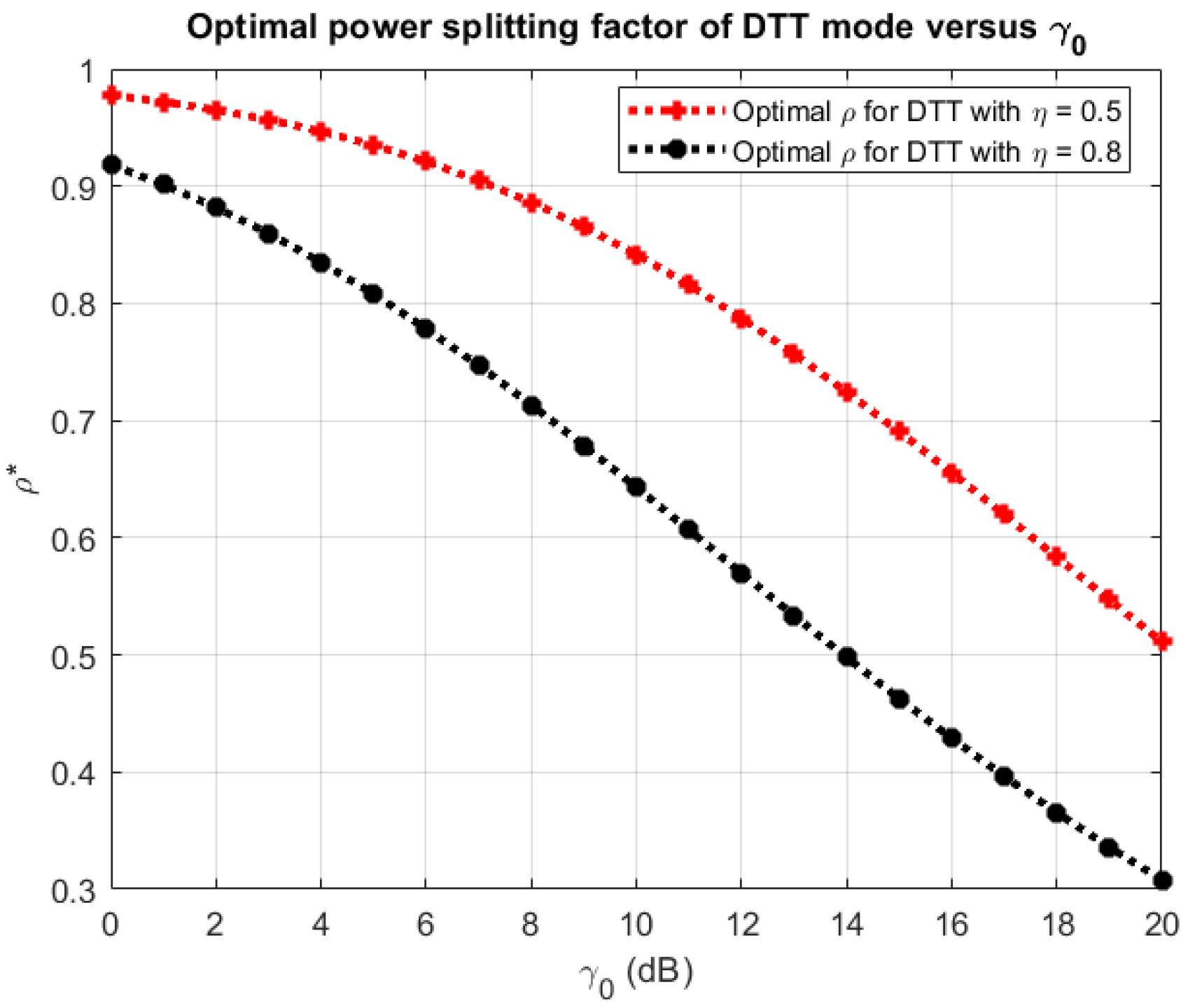
3.3. Optimal PS Factor

The optimal PS factor value ρ * can be obtained by solving the equation d R D L ( ρ ) d ρ = 0 . This mathematical algorithm is based on the global optimization problems in communication networks, as shown in [19]. More detail of this algorithm and the theory can be followed as shown in [21].

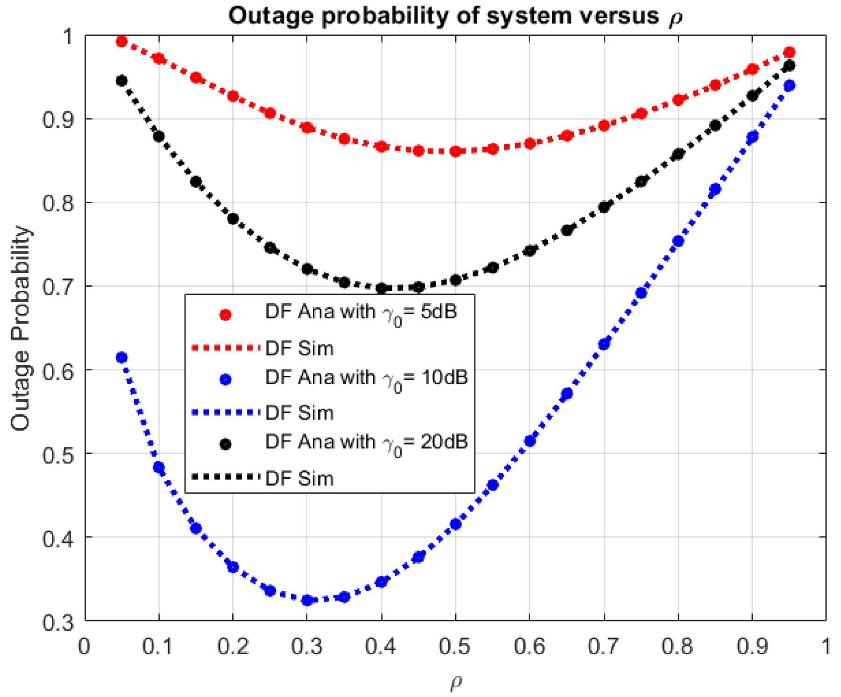
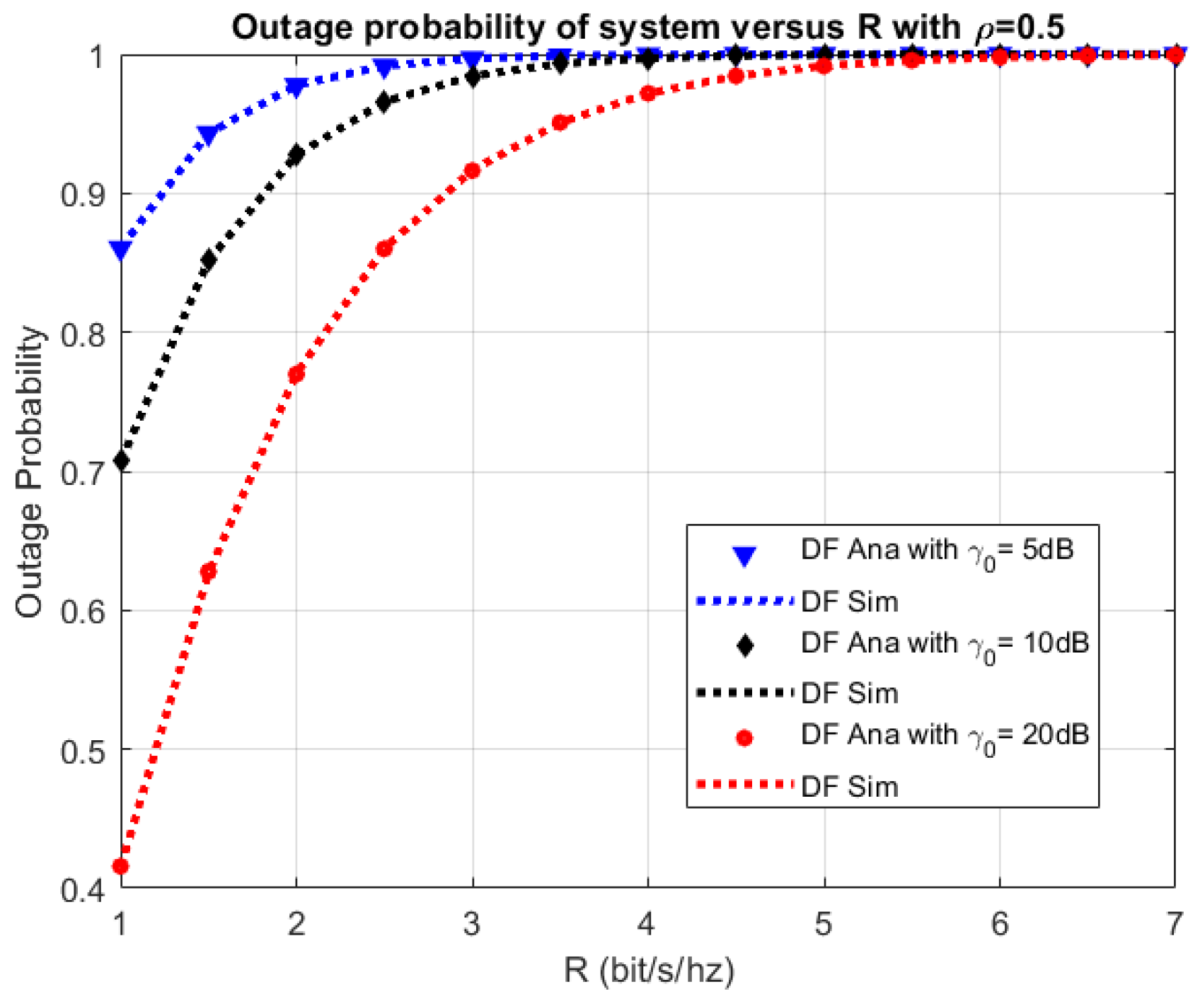
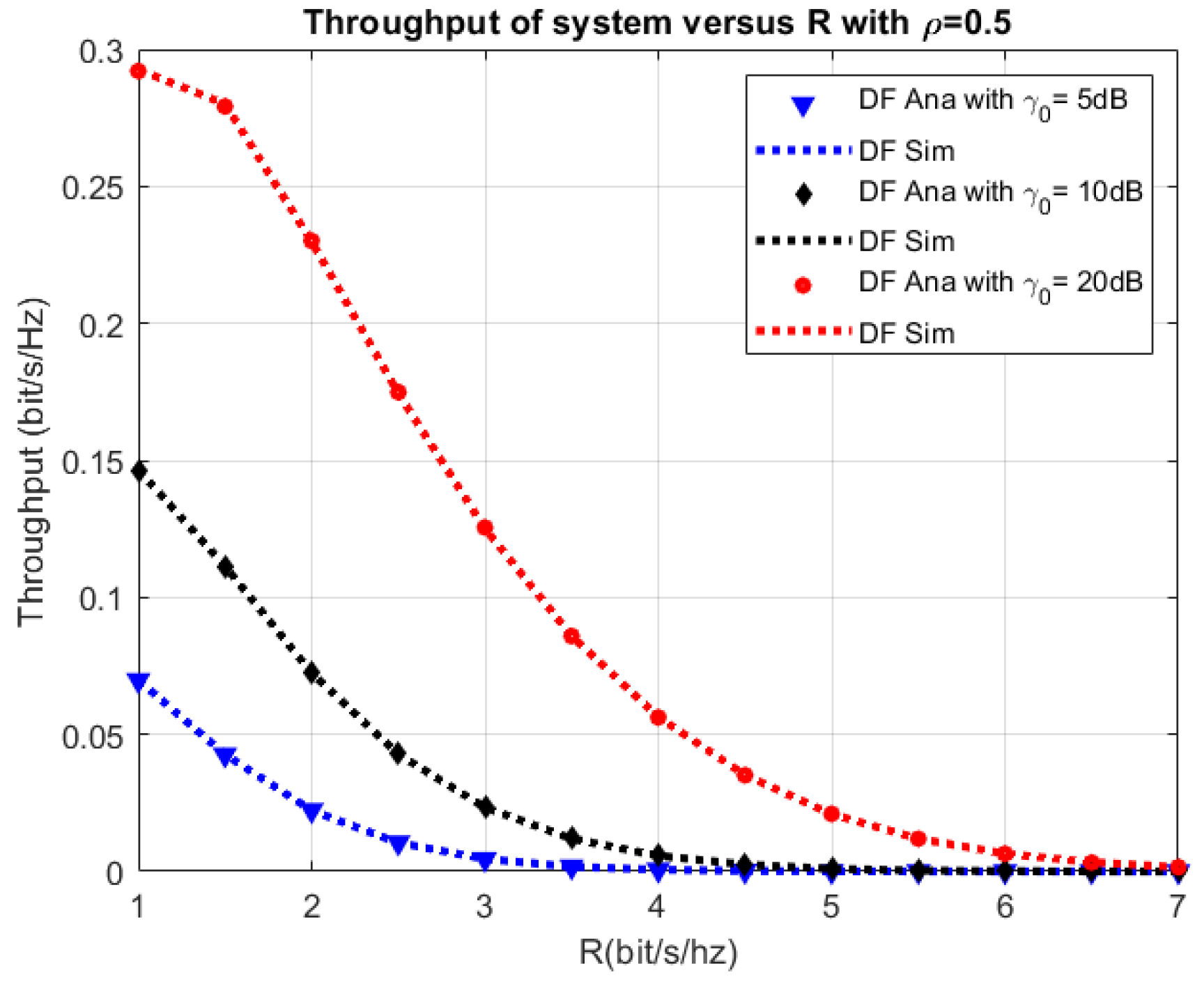
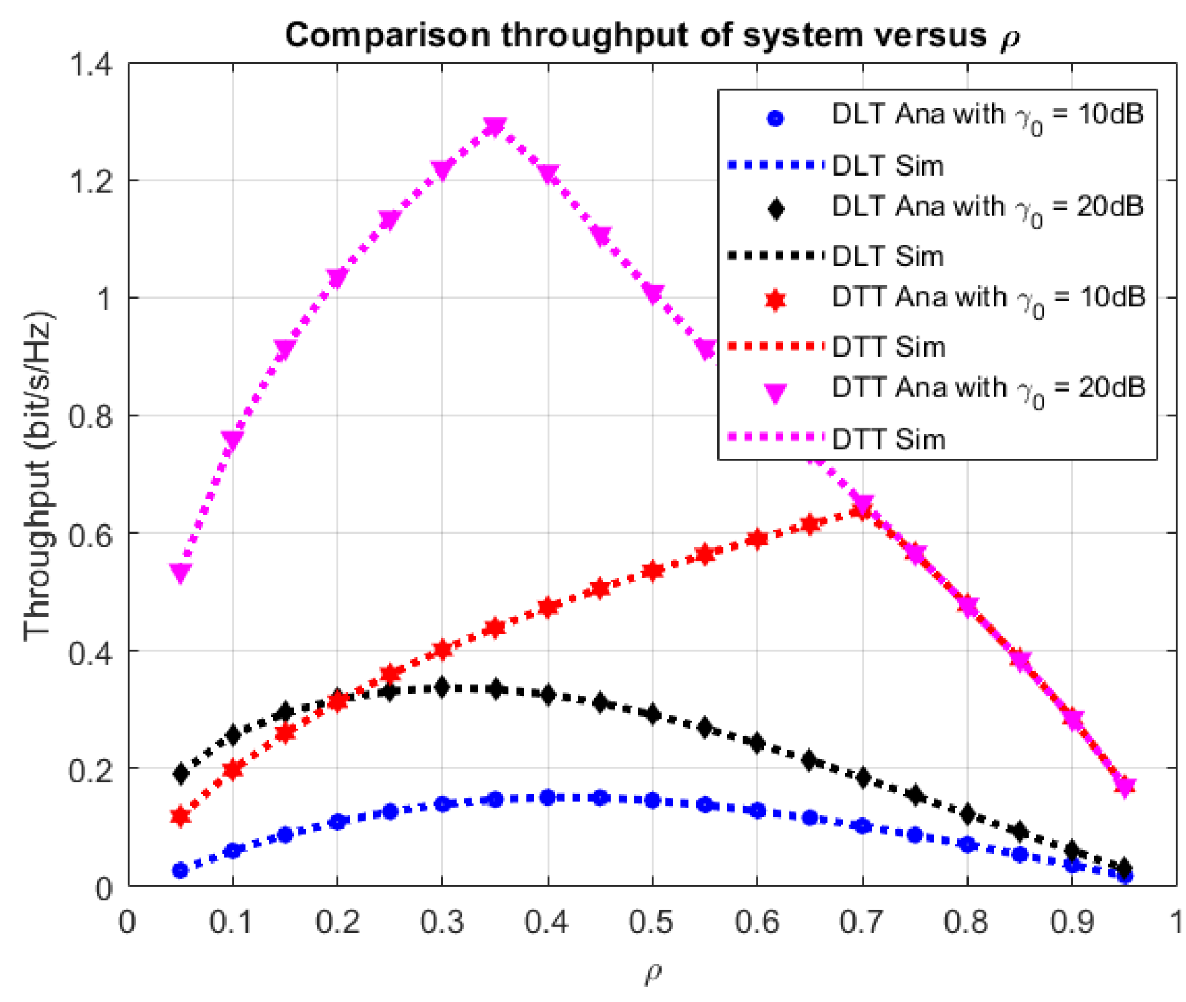
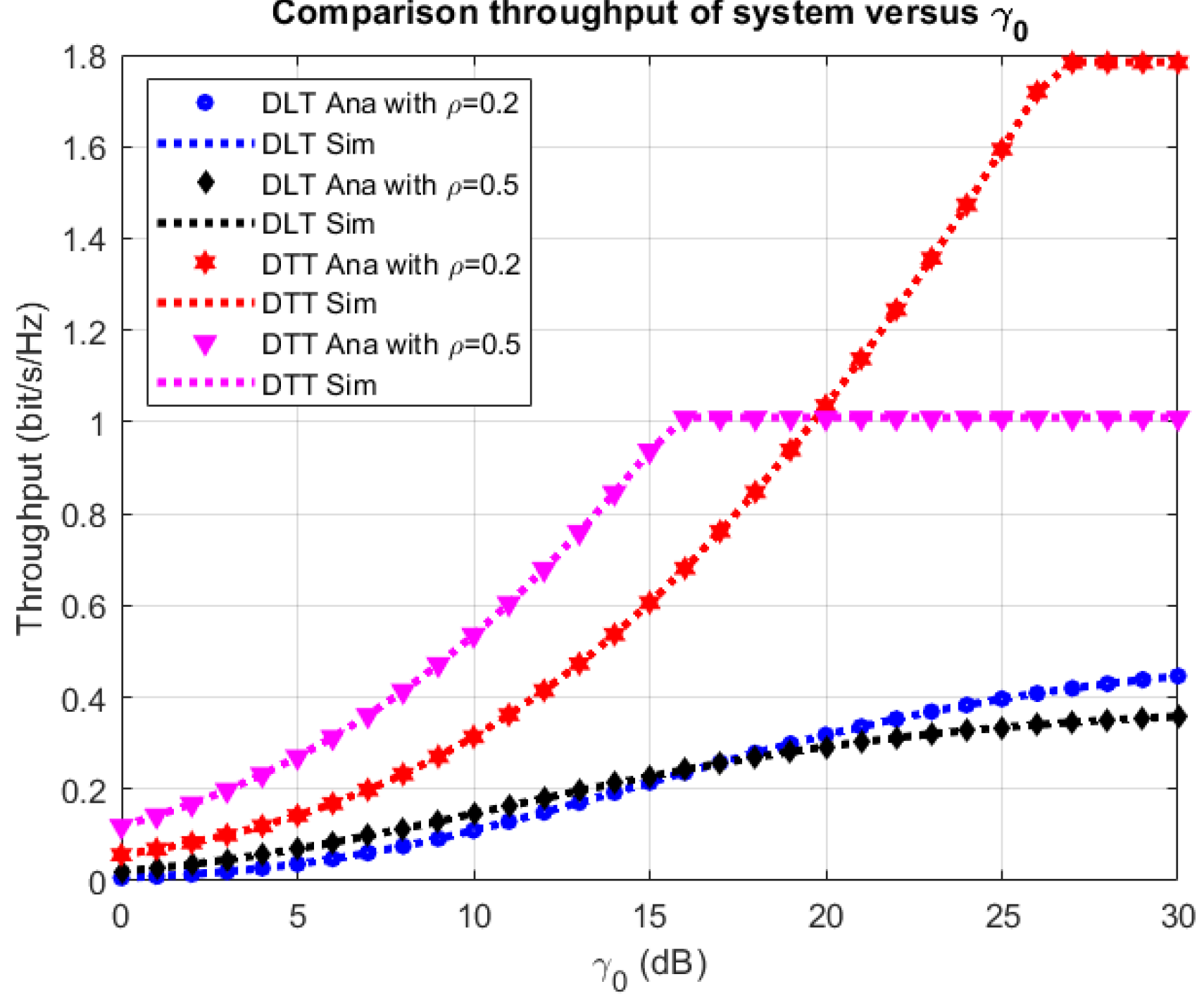
4. Numerical Results and Discussion

In Section 4, the Monte Carlo simulation is conducted for validation of the correctness of the system performance analysis in terms of the derived OP and EC expressions. In addition, we investigate the influence of the primary system parameters on system performance. The comparison of the analytical and the simulation results are provided by generating 106 random samples of each Rayleigh distributed channel gain [22,23,24,25,26,27,28]. The analytical and simulation results should match together to verify the correctness of our analysis. In Table 1, we propose some main system parameters.
Figure 3 and Figure 4 show the OP and ST versus ρ. In Figure 3 and Figure 4, we set γ 0 at 5 dB, 10 dB, and 15 dB, respectively, where α = 0.5 and ρ varies from 0 to 1. From Figure 3 and Figure 4, the OP has a slight decrease when ρ increases from 0 to 0.3, and then has a significant increase. Moreover, Figure 3 shows that the ST falls as ρ increases from 0.3 to 1 and increases with ρ from 0 to 0.3, respectively. The gain of the PS factor means that more power is harvested in the R node and less energy is used for transferring the information to the D node. This fact causes more OP and less ST in the model system. In both Figure 3 and Figure 4, the analytical and simulation results agree very well with each other. Furthermore, Figure 5 and Figure 6 propose the effect of η on the OP and ST with α = 0.5 , ρ = 0.2, 0.6, 0.9, and γ 0 at 10 dB. From Figure 5, we can see that the OP decreases while η increases from 0 to 1, and as shown in Figure 6, the ST has a considerable improvement when η increases from 0 to 1. In all the above figures, the analytical values match well with the simulation values.
Moreover, the OP and ST versus R are shown in Figure 7 and Figure 8, respectively. Similarly, we set at γ 0 at 5, 10, and 20 dB; α = 0.5 ; and ρ at 0.5. From Figure 7, we see that the OP increases. This result is because the higher source rate R can lead to improving the ST and decreasing the system OP. In contrast, the ST decreases (Figure 8). Then, Figure 9 and Figure 10 present the effect of the ratio γ 0 to the OP and ST, while we set α = 0.5 and ρ = 0.3, 0.5, and 0.7. In addition, Figure 11 and Figure 12 show the optimal PS factor of the proposed system at α = 0.5 , R = 0.5, and 2 bps. From these figures, we show that the optimal PS factor significantly decreases with increasing γ 0 . Similarly, we set γ 0 in all figures, and the analytical values are the same with the simulation values.
Finally, Figure 13, Figure 14 and Figure 15 plot the ST comparison between DLT and DTT modes in connection with ρ, γ 0 , and α, respectively. In this simulation, we set γ 0 at 10 and 20 dB and ρ from 0 to 1 (Figure 13), ρ = 0.2 and 0.5 and γ 0 from 0 to 30 dB (Figure 14), and ρ = 0.5, γ0 = 10 and 20 dB and α from 0 to 1 (Figure 5). The results show that the ST in the DTT mode is better than that in the DLT mode, and all the analytical and simulation results are the same.

5. Conclusions

In this paper, an FD PB EH relaying cooperative network with PS protocol in DLT and DTT modes is investigated. For the system performance analysis, the closed-form mathematical expressions of OP, EC, and ST are proposed and derived in the PS protocol with both DLT and DTT modes. Moreover, the analytical analysis is convinced entirely by the Monte Carlo simulation in connection with the primary system parameters. The results show that all the analytical and simulation results agreed well with each other. In addition, the optimal PS factor also is demonstrated. The research results can provide the recommendation for improving the system performance of the FD PB EH relaying cooperative network.

Author Contributions

Methodology, P.T.T. and D.H.H.; Data curation, D.H.H.; software, P.T.T., B.H.D. and T.T.T.; validation, P.T.T., B.H.D. and T.T.T.; writing—original draft preparation, B.H.D.; writing—review and editing, T.N.N., B.H.D.; supervision, T.N.N. All authors have read and agreed to the published version of the manuscript.

Funding

This research received no external funding.

Conflicts of Interest

The authors declare no conflict of interest.

References

  1. Bi, S.; Ho, C.K.; Zhang, R. Wireless powered communication: Opportunities and challenges. IEEE Commun. Mag. 2015, 53, 117–125. [Google Scholar] [CrossRef] [Green Version]
  2. Niyato, D.; Kim, D.I.; Maso, M.; Han, Z. Wireless Powered Communication Networks: Research Directions and Technological Approaches. IEEE Wirel. Commun. 2017, 24, 88–97. [Google Scholar] [CrossRef]
  3. Yu, H.; Lee, H.; Jeon, H. What is 5G? Emerging 5G Mobile Services and Network Requirements. Sustainability 2017, 9, 1848. [Google Scholar] [CrossRef] [Green Version]
  4. Zhou, X.; Zhang, R.; Ho, C.K. Wireless Information and Power Transfer: Architecture Design and Rate-Energy Tradeoff. IEEE Trans. Commun. 2013, 61, 4754–4767. [Google Scholar] [CrossRef] [Green Version]
  5. Nguyen, T.N.; Tran, M.; Ha, D.; Trang, T.T.; Voznak, M. Multi-source in DF Cooperative Networks with the PSR Protocol Based Full-duplex Energy Harvesting over a Rayleigh Fading Channel: Performance Analysis. Proc. Est. Acad. Sci. 2019, 68, 264. [Google Scholar] [CrossRef]
  6. Nguyen, T.N.; Tran, M.; Nguyen, T.L.; Ha, D.H.; Voznak, M. Performance Analysis of a User Selection Protocol in Cooperative Networks with Power Splitting Protocol-Based Energy Harvesting Over Nakagami-m/Rayleigh Channels. Electronics 2019, 8, 448. [Google Scholar] [CrossRef] [Green Version]
  7. Nguyen, T.; Quang Minh, T.; Tran, P.; Vozňák, M. Energy Harvesting over Rician Fading Channel: A Performance Analysis for Half-Duplex Bidirectional Sensor Networks under Hardware Impairments. Sensors 2018, 18, 1781. [Google Scholar] [CrossRef] [Green Version]
  8. Gu, Y.; Chen, H.; Li, Y.; Vucetic, B. An adaptive transmission protocol for wireless-powered cooperative communications. In Proceedings of the IEEE International Conference on Communications (ICC), London, UK, 8–12 June 2015; pp. 4223–4228. [Google Scholar]
  9. Ju, H.; Zhang, R. Throughput Maximization in Wireless Powered Communication Networks. IEEE Trans. Wirel. Commun. 2014, 13, 418–428. [Google Scholar] [CrossRef] [Green Version]
  10. Bhatnagar, M.R. On the Capacity of Decode-and-Forward Relaying over Rician Fading Channels. IEEE Commun. Lett. 2013, 17, 1100–1103. [Google Scholar] [CrossRef] [Green Version]
  11. Nasir, A.A.; Zhou, X.; Durrani, S.; Kennedy, R.A. Relaying Protocols for Wireless Energy Harvesting and Information Processing. IEEE Trans. Wirel. Commun. 2013, 12, 3622–3636. [Google Scholar] [CrossRef] [Green Version]
  12. Tan, N.; Nguyen, T.H.Q.; Minh, P.; Tran, T.; Voznak, M. Adaptive Energy Harvesting Relaying Protocol for Two-Way Half Duplex System Network over Rician Fading Channels. Wirel. Commun. Mob. Comput. 2018, 2018, 10. [Google Scholar]
  13. Gu, Y.; Aissa, S. RF-Based Energy Harvesting in Decode-and-Forward Relaying Systems: Ergodic and Outage Capacities. IEEE Trans. Wirel. Commun. 2015, 14, 6425–6434. [Google Scholar] [CrossRef]
  14. Li, T.; Fan, P.; Letaief, K.B. Outage Probability of Energy Harvesting Relay-Aided Cooperative Networks over Rayleigh Fading Channel. IEEE Trans. Veh. Technol. 2016, 65, 972–978. [Google Scholar] [CrossRef]
  15. Ma, Y.; Chen, H.; Lin, Z.; Li, Y.; Vucetic, B. Distributed resource allocation for power beacon-assisted wireless-powered communications. In Proceedings of the IEEE International Conference on Communications (ICC), London, UK, 8–12 June 2015; pp. 3849–3854. [Google Scholar]
  16. Huang, K.; Lau, V.K.N. Enabling Wireless Power Transfer in Cellular Networks: Architecture, Modeling and Deployment. IEEE Trans. Wirel. Commun. 2014, 13, 902–912. [Google Scholar] [CrossRef] [Green Version]
  17. Park, J.-H.; Jeon, Y.-S.; Han, S. Energy Beamforming for Wireless Power Transfer in MISO Heterogeneous Network With Power Beacon. IEEE Commun. Lett. 2017, 21, 1163–1166. [Google Scholar] [CrossRef]
  18. Zhong, C.; Jin, S.; Wong, K.-K.; Mckay, M.R. Ergodic Mutual Information Analysis for Multi-Keyhole MIMO Channels. IEEE Trans. Wirel. Commun. 2011, 10, 1754–1763. [Google Scholar] [CrossRef]
  19. Duong, T.Q.; Duy, T.T.; Matthaiou, M.; Tsiftsis, T.; Karagiannidis, G.K. Cognitive cooperative networks in dual-hop asymmetric fading channels. In Proceedings of the IEEE Global Communications Conference (GLOBECOM), Atlanta, GA, USA, 9–13 December 2013; pp. 955–961. [Google Scholar]
  20. Zwillinger, D. Table of Integrals, Series, and Products; Springer: New York, NY, USA, 2015. [Google Scholar] [CrossRef]
  21. Chong, E.K.P.; Zak, S.H. An Introduction to Optimization, 4th ed.; Wiley: New York, NY, USA, 2013; pp. 1–640. [Google Scholar]
  22. Nguyen, T.N.; Minh, T.H.Q.; Tran, P.T.; Voznak, M.; Duy, T.T.; Nguyen, T.L.; Tin, P.T. Performance Enhancement for Energy Harvesting Based Two-way Relay Protocols in Wireless Ad-hoc Networks with Partial and Full Relay Selection Methods. Ad Hoc Netw. 2019, 84, 178–187. [Google Scholar] [CrossRef]
  23. Tan, N.; Phuong, N.; Tran, T.; Minh, T.H.Q.; Voznak, M. Two-Way Half Duplex Decode and Forward Relaying Network with Hardware Impairment over Rician Fading Channel: System Performance Analysis. Elektron. Ir Elektrotechnika 2018, 24, 74–78. [Google Scholar]
  24. Phan, V.D.; Nguyen, T.N.; Tran, M.; Trang, T.T.; Voznak, M.; Ha, D.H.; Nguyen, T.L. Power Beacon-Assisted Energy Harvesting in a Half-Duplex Communication Network under Co-Channel Interference over a Rayleigh Fading Environment: Energy Efficiency and Outage Probability Analysis. Energies 2019, 12, 2579. [Google Scholar] [CrossRef] [Green Version]
  25. Nguyen, T.N.; Tran, M.; Ha, D.H.; Nguyen, T.L.; Vozňák, M. Energy Harvesting Based Two-way Full-duplex Relaying Network over a Rician Fading Environment: Performance Analysis. Proc. Est. Acad. Sci. 2019, 68, 111. [Google Scholar] [CrossRef]
  26. Nguyen, T.; Tran, M.; Nguyen, T.L.; Ha, D.H.; Voznak, M. Multisource Power Splitting Energy Harvesting Relaying Network in Half-Duplex System over Block Rayleigh Fading Channel: System Performance Analysis. Electronics 2019, 8, 67. [Google Scholar] [CrossRef] [Green Version]
  27. Nguyen, T.N.; Tran, M.; Tran, P.T.; Tin, P.T.; Nguyen, T.L.; Ha, D.H.; Voznak, M. On the Performance of Power Splitting Energy Harvested Wireless Full-Duplex Relaying Network with Imperfect CSI over Dissimilar Channels. Secur. Commun. Netw. 2018, 2018, 6036087. [Google Scholar] [CrossRef]
  28. Nguyen, T.; Tran Tin, P.; Ha, D.; Voznak, M.; Tran, P.; Tran, M.; Nguyen, T.L. Hybrid TSR–PSR Alternate Energy Harvesting Relay Network over Rician Fading Channels: Outage Probability and SER Analysis. Sensors 2018, 18, 3839. [Google Scholar] [CrossRef] [PubMed] [Green Version]
Figure 1. The relaying network model.
Symmetry 12 00106 g001
Figure 2. The energy harvesting (EH) and delay-tolerant (DT) processes in the power-splitting (PS) protocol.
Symmetry 12 00106 g002
Figure 3. Outage probability (OP) versus ρ.
Symmetry 12 00106 g003
Figure 4. System throughput (ST) versus ρ.
Symmetry 12 00106 g004
Figure 5. OP versus η.
Symmetry 12 00106 g005
Figure 6. ST versus η.
Symmetry 12 00106 g006
Figure 7. OP versus relay (R).
Symmetry 12 00106 g007
Figure 8. ST versus relay (R).
Symmetry 12 00106 g008
Figure 9. OP versus γ 0 .
Symmetry 12 00106 g009
Figure 10. ST versus γ 0 .
Symmetry 12 00106 g010
Figure 11. Optimal PS factor versus γ 0 in delay-limited transmission (DLT).
Symmetry 12 00106 g011
Figure 12. Optimal PS factor versus γ 0 in delay-tolerant transmission (DTT).
Symmetry 12 00106 g012
Figure 13. ST comparison between DTT and DLT versus ρ.
Symmetry 12 00106 g013
Figure 14. ST comparison between DTT and DLT versus γ 0 .
Symmetry 12 00106 g014
Figure 15. ST comparison between DTT and DLT versus α .
Symmetry 12 00106 g015
Table 1. Simulation parameters.
SymbolNameValues
η b = η s = η Energy-harvesting efficiency0.05–0.95
λ b s Mean of | h b s | 2 0.5
λ r r Mean of | h r r | 2 0.5
λ s r Mean of | h s r | 2 0.5
λ r d Mean of | h r d | 2 0.5
γthSNR threshold1
PB/N0Beacon power-to-noise ratio0–30 dB
RSource rate1 bps/Hz
ρPower-splitting factor0.05–0.95
αTime-switching factor0.05–0.95

