Article

A Novel Linear Antenna Synthesis for Linear Dispersion Codes Based on an Innovative HYBRID Genetic Algorithm

1
School of Information Science & Engineering, Dalian Polytechnic University, Dalian 116034, China
2
School of Electronic, Electrical and Computer Engineering, the University of Western Australia, M350, Perth WA 6009 Australia
*
Author to whom correspondence should be addressed.
Symmetry 2019, 11(9), 1176; https://doi.org/10.3390/sym11091176
Submission received: 9 August 2019 / Revised: 11 September 2019 / Accepted: 11 September 2019 / Published: 17 September 2019

Abstract

:
As far as taking-away of the symmetry constraints is concerned, as a scientifically symmetry problem, the global synthesis for antenna arrays that produce the desired radiation pattern is also a highly nonlinear optimization issue in fact. Besides this, the built criteria offer the reasonable power patterns. The consequent synthesis could be implemented by looking for a nominal pattern. When the criteria are already sufficient, it can simply do the whole synthesis process. To utilize multiple antennae, a method to choose a transmit antenna for the linear dispersion codes (LDC-TAS) is implemented in this paper. The authors used the max–min-post- signal to noise ratio (SNR) criteria to select these optimal transmitting antennae while this dependent, linear receiver is applied to the varying and slow channel. The simulated results illustrate that this max–min-post-SNR criterion outperforms the Bell Labs layered space time transmitting antenna selection (BLAST-TAS) applying the same spectral efficiency than space–time block codes (STBC)-TAS in the environment with low SNR. Furthermore, once the M antennae are selected under the selection criteria, a max–min-post-SNR rule, a novel linear antenna synthesis to linear dispersion codes on the basis of an innovative HYBRID (of mixed characters or solutions) genetic algorithm has been presented and evaluated to formulate and address the optimal problem to non-uniformly spaced and linear arrays. The restricted side-lobes level, the main-lobe width, and the shaped beam pattern are contemporarily concerned via maximizing a pretty suitable cost function through the innovational advanced genetic-algorithm-based algorithm. The method proposed in this paper can provide flexibility and a simple insertion of the a priori knowledge under a small computing pressure. At last, a computing simulation is completed well and the results are shown. It should be noticed that some extensions of the presented method could also be easily utilized without an obvious increase in the algorithm complexity.

1. Introduction

An array of the antennae can offer an efficient way for processing and detecting the signals coming from some different orientations. Contrasted to a single antenna, a specific array of sensors is able to have its own beam pattern modified through the amplitude and phase distribution named the weights of this array. In order to achieve an array beam pattern of the antennae, the signals could be power weighted and accumulated once the pre-process on the antenna outputs is over. The problem on the antenna array pattern synthesis includes how to get the weights to satisfy a series of specifications over the beam pattern.
In this paper, we make the purpose of proposing a specific modular algorithm on the basis of the genetic algorithms (GAs) for various restrictions, just like the array thinned, the linear dimension minimization, the side-lobes peak minimization, BP (beam pattern) shape modeling, etc. Some completely experimental instances show that the method presented can work well. The presented GAs-based processing method is suitable and flexible to the antenna array.
Contrasted to the traditional SISO system (single-input single-output system), the MIMO system (multiple-input multiple-output system) can provide a huge capacity gain [1,2]. Assuming that only the receiver has known the channel state information, the MIMO system has two modulation methods: Diversity and multiplexing [3,4]. The orthogonal space–time block codes do not achieve the overall channel capacity in the MIMO channels in spite of its advantage of maximizing the diversity. Scientists Hassibi and Hochwald [5] firstly presented the revolutionary linear dispersion codes (LDCs). The researcher Robert W. Heath [6] proposed a family of LDC designs on the basis of the frame theory, which certifies good performance in terms of the diversity advantage. While the MIMO system can increase system capacity and assure communication quality, but an introduction of multiple RF (Radio Frequency) links requires additional requirements according to volume, power consumption, and costs of the hardware. Therefore, antenna selection becomes a cheap and low-complexity application method [5]. Space–time coding schemes, involved in STTC (space–time trellis codes) [6,7] and STBC (space–time block codes) [8,9], have also been studied. Reference [10] proposes a BLAST-TAS (Bell Labs layered space time transmitting antenna selection) system for zero-force (ZF) receivers.
The multiple antenna system can improve the reliability and increase the capacity in the mobile communication. However, the RF chains are expensive depending on size, the hardware and the power. Consequently, the antenna selection intends to be the lower cost and lower complexity alternative scheme to catch a lot of the merits of the MIMO systems [11]. In order to apply multiple antennae, some articles [11,12,13,14,15] have already come out lately in the research report in which the conception over the antenna selection was proposed for the space–time codes. Other authors [16,17] proposed a complete performance analysis on orthogonal STBCs using the antenna selection. The quasi-orthogonal STBCs were researched in some papers [18,19].
In order to increase the transmission rate and improve the diversity gain of the system, the article used a transmit antenna selection [11,12] scheme based on linear dispersion code (LDC-TAS). This system scheme adopts the minimum posterior signal to noise ratio (SNR) criterion, which can be applied to any configuration of the number of antennae at both transmitters and receivers, so as to provide diversity capability [13,14] under the condition of maximizing mutual information between transmitters and receivers. The computer simulation results illustrate that the minimum posterior SNR criterion outperform the other criterions under the different modulation ways just like 8PSK, 16QAM, and QPSK. Additionally, Contrasted to BLAST-TAS [15], this presented method still has significant diversity gain at the same spectral efficiency as well as low signal-to-noise ratio.
The global combining for antenna arrays that produce the desired radiation pattern [16,17,18] is also a nonlinear optimization issue. A number of mathematical algorithms have already been presented on this solution. Those examples of the analytical technologies including the Chebishev [19] method and Taylor algorithm [20], which are both well-known. Nevertheless, the calculus or analytical ways commonly used cannot optimize the power weights and positions of the array elements at the same time. To treat huge nonlinear searching spaces and enlarge the research to include an efficient placement of elements, stochastic methods are essential.
The problem-oriented genetic algorithms (GAs) have been extended to utilize some different experimental instances [21,22,23]. As for the symmetrical array synthesis, the real-coded GA-based process was presented in the article [24] to optimize the array power weights while sensors are λ/2-spaced. Moreover, the binary genetic method [25] was utilized to address the problem of isophorical array thinning, and the stochastic approach was proposed [26] to optimize isophorical arrays with a certain number of the elements. The methods above consider symmetric arrays to reduce the calculating time.
However, then this arrays optimizing [27,28] have already been researched via considering one higher number of degrees of freedom just like the elements position as well as weighting. From then on, the optimization algorithm based on a simulation annealing procedure was used in order to optimize both the positions and power weights, and in the article [29,30] to the beam pattern shaping and the global array combinations [31,32,33].
The arrangement of the article is organized as the following parts. After authors offer the specific background of this paper in advance. Firstly, the linear dispersion code is reviewed in Section 2. Secondly, a model of the system over the LDC-TAS is introduced, then some assumptions are also offered inside Section 3, and the full description about the antenna selection methods for LDCs based on ZF receiver is shown in detail in Section 4. Thirdly, in Section 5, this paper focuses on proposing that the modular algorithm, according to the genetic algorithm, can combine the linear real-weighted arrays based on different restrictions, including arrays thinning, the side-lobe peak minimization, the beam pattern (BP) shape modeling, and the minimization of the linear dimension. Then, Section 6 includes the numerical computing simulation results and the complete analysis to those results. Finally, Section 7 presents our conclusions.

2. Linear Dispersion Code
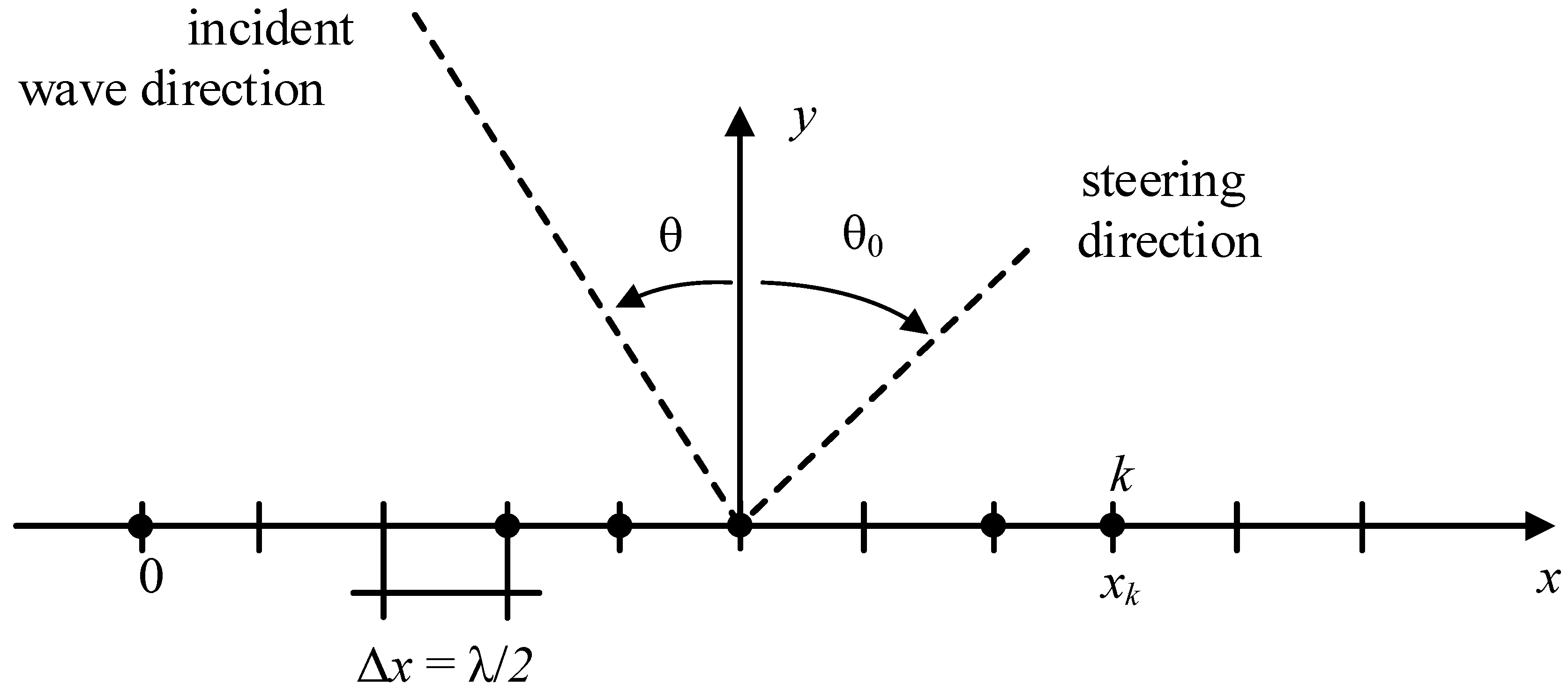
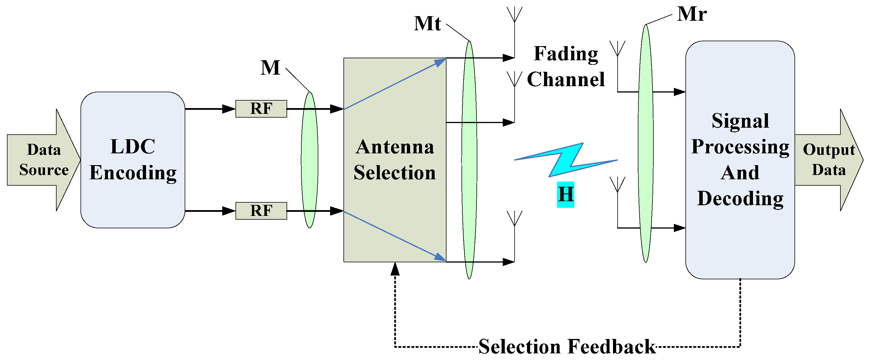
The linear discrete code was first proposed by [34,35,36], which maximizes the mutual information of transceiver ends. The LDC encoder uses a linear combination of a series of base matrices to construct space–time codewords [37,38]. Supposing that { S n } n = 0 N 1 is a set of the scalar symbols to be sent selected from a specific complex constellation set C , { M n } n = 0 N 1 is a M × T base matrix codeword, and the base matrix set is stored at both ends of the transceiver. In it, M is an actual number of transmitting antennae, and T is the duration time of the codeword. Supposing that the mean and variance of S n satisfy: ε { S n } = 0 , ε { | S n | 2 } = 1 , and the formula ε { · } is the expected value. Then, the power limitation condition should be met by the basis matrices:
t r { M n M n H } = T N   n = 0 ,   1 ,   ,   N 1
The corresponding transmitter code corresponding to { s n } n = 0 N 1 can be constructed by a linear combination of the base matrix and s n weighting coefficients.
S ( s 0 , s 1 , , s N 1 ) = n = 0 N 1 { M n s n } .
As for the MIMO system of M transmitting antennae Mr receiving antennae [39]. After matched filtering and symbol level sampling, the received signal matrix in the receiving antenna array is:
Y = E s H s S ( s 0 , s 1 , , s N 1 ) + V = E s H s n = 0 N 1 { M n s n } + V
In it, the received antenna signal matrix in Formula (1) is Y , H s is the MIMO channel coefficient matrix [40,41], and the complex AWGN (additive white Gaussian noise) Mr × T matrix is V , in which all elements are not dependent and identically distributed complex Gaussian random variables in a complex domain with a distribution is C N ( 0 , N 0 ) . Es is the total power transmitted on the M transmitting antenna. The SNR (signal to noise ratio) of those receiving antennae is written by S N R : = E s / N 0 . At this point, the spectrum efficiency of the system is defined as:
R = l o g 2 | C | · N T   b / s / H z .
In above, | C | indicates the potential of the constellation set C , which is the number of all possible constellations [42,43].

3. System Model

The block diagram of the transmit antenna selection system based on LDC (LDC-TAS) [44,45] is shown in Figure 1, it is easily found that there is a feedback circle link between the receiver with the transmitter in the system. It is supposed that being Mt transmitting antennae and Mr receiving antennae in it, but just M transmit antennae are selected by the transmitter to transmit. H being a M r × M t channel coefficient array whose elements are absolutely independent and its distribution is C N ( 0 , 1 ) . At the same time, supposing the receiver has known an ideal CSI (channel status information), and given the channel state H and { M n } n = 0 N 1 , then the M r × M t channel array Hs can be selected by one function below:
: C M r × M t H ^ = { H 1 , H 2 , H 3 , H P } .

4. Maximum Minimum Posterior SNR Criterion for the LDC-TAS

As mentioned above, H s is a more effective channel coefficient array chosen from that function .
H s = ( H )
For convenience of analysis, defining a linear transferring array:
χ : = [ v e c ( M 0 ) ,   v e c ( M 1 ) ,   ,   v e c ( M N 1 ) ]
So the channel coefficient matrix can be expressed as
H s ¯ = I T H s
In the equation, v e c ( · ) is the vectorization operator, and is the Kronecker product, so Y can be re-written as below:
y = E s H s ¯ χ s + v = E s H s ˜ + v .
In it, y = v e c ( Y ) ,   s = [ s 0 ,   s 1 ,   s 2 , s N 1 ] T ,   v = v e c ( V ) ,   a n d H s ˜ : = H s ¯ χ being the M r T × N matrix of the equivalent channel coefficient.
From the expression above, any decoding technology, which is suitable for BLAST can be applied for the LDC system decoding. Due to the complexity of the real practical system, only the linear receiver is taken into account in this article. When the N × M r T matrix equalizer G is multiplied to y , an estimated s can be achieved as below:
S ^ = G y = E s G H s ˜ + G v .
The original information can be recovered from S ^ . According to the zero-force (ZF) receiver:
G = H ˜ + .
However, for MMSE receivers, G can be written as:
G = ( H ˜ H H ˜ + N 0 E s ) 1 H ˜ H .
Maximum minimum posterior SNR criterion: Corresponding in ZF receiver, to N multiplexed sub streams, a posteriori SNR is:
S N R n Z F ( H k ) = E s N N 0 [ H ˜ k H H ˜ k ] n n 1 .
For each element in the collection H , conjugate transposition of matrices is ( ) H , we should calculate the minimum SNR in the corresponding N multiplexed sub streams. As for each element of the set H ^ , a minimum SNR of the corresponding N streams is calculated, so an antenna subset using the most maximum minimum SNR can be chosen.
H s = arg max [ min ( SNR N ZF ( H k ) ) ] .
The bit error rate (BER) and frame error rate (FER) profiles of these two systems are displayed in Figure 2. It is obviously seen that the LDC-TAS performance outperformed STBC-TAS, while the SNR was lower than 14 dB. While SNR was at a high level, because STBC could achieve full diversity gain, its performance was indeed better than LDC-TAS.
BLAST-TAS used four transmitters and two receivers, QPSK modulation, two antennae for transmission; LDC-TAS used 16QAM modulation, T = 3. It means that their spectral efficiency of these two systems was exactly R = 3 bit/s/Hz. The FER and BER profiles of these two systems are displayed in Figure 3. LDC-TAS shows a significant diversity gain contrasted to BLAST-TAS under the equal spectral efficiency. It is worth mentioning that LDC-TAS approximately had a 6 dB performance gain of the system when BER reached 10−2, moreover, with the increase of SNR, the performance gain was higher.

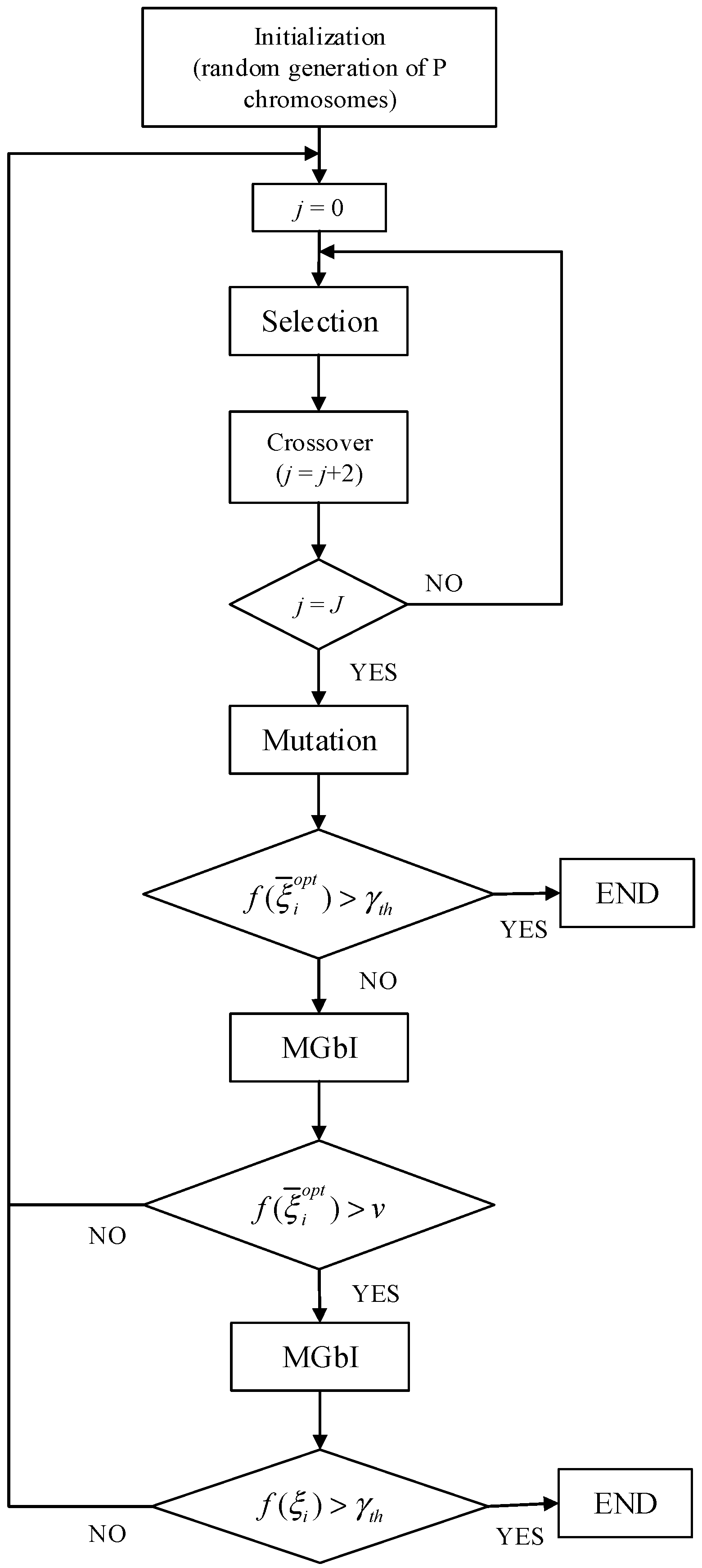
5. Antenna Synthesis Via an Innovative HYBRID Genetic Algorithm

When the antenna subset H s , which is the M r × M t channel coefficient matrix [46], was selected via the minimum posterior SNR criterion mentioned in part 4 above, we could think about a linear array displayed in the Figure 4, where the M non-uniform spaced elements were all located alongside an exactly straight line L in the positions xk, k = 0, 1, 2, 3, …, M − 1.
The parameter M can be calculated by the Equations (6) and (14), which are derived in part 4, and the beam pattern (BP) function of the matrix, p(u), being achieved as below:
p ( u ) = k = 0 M 1 w k e j 2 π λ x k u .
In Equation (15), wk being the weighting coefficients of the kth element, λ means the wavelength of the propagation channel, u = sin θ − sin θ0, and θ0 and θ are respectively the steering angles of these arrays and the incident angle of the impinging plane wave. It is very essential to combine an array configuring to produce a BP that meets some requirements (e.g., side lobes level (SLL)) or rebuilds a special shape (pref (u)).
First of all, we defined the fitness function f that symbolizes a measurement of the difference among desired and combined BP [47,48], as follows:
f ( ζ ¯ ) = 1 k 1 f S L L ( ζ ¯ ) + k 2 f B P ( ζ ¯ ) + k 3 f N ( ζ ¯ ) + k 4 f D ( ζ ¯ ) ,
where ζ ¯ = [M; x0, …, xk, …, xM−1; w0, …, wk, …, wM−1]t being the uncertain quantity arrays and where:
f S L L ( ζ ¯ ) = Q max u s t a r t u 1 { P d B ( u ) } ,
f B P ( ζ ¯ ) = u S ( P d B ( u ) Q P d B r e f ( u ) ) d u , f N ( ζ ¯ ) = M , f D ( ζ ¯ ) = D
In the above equations, μ s t a r t is a threshold, which allows removing the main-lobe, which could be derived from the computation of the SLL (side-lobes level) [49,50,51]. Moreover, D is an aperture of the array, Q is a normalized constant parameter, S is a region of these values for {pdB (u)/Q} > p d B r e f ( u ) , but p d B r e f ( u ) is a desired BP shape. Finally, based on the optimization method, k1, k2, k3, and k4 were all selected as the normalized parameters.
A fitness function f that has been assumed in Expression (2) is extremely non-linear with a lot of the local peak values, where the deterministic processes can be captured. Accordingly, in order to address the maximization issue at hand, we applied a stochastic algorithm to remove these local maxima and effectively explore highly nonlinear search spaces. The GAs already displayed their correctness and pretty effectiveness for optimizing those antenna arrays and seem to be the most possible, feasible, and reasonable option.
GAs are optimization algorithms that are basically built on Darwin’s Theory of Evolution. The method assumes an evolution process for a population of these individuals (i.e., a set of experimental ways for the solved problem dealt with) in time that are improving some individual characteristics (i.e., the fitness with several constraints assessed using fitness function f).
Standard GAs (SGAs) are very different from those other methods with the optimization aims for the following reasons [16,17]:
  • These SGAs cooperate with the parameters’ coding over computation, not these parameters themselves;
  • These SGAs being a multiple-agent hunting process (i.e., a multiple sampling of those hunting spaces);
  • These SGAs do not have to make use of those derivatives indeed;
  • These SGAs do not apply the deterministic transition schemes, but use some random ones instead.
According to the study [18], these SGAs need to be made for every application to obtain the best results. Consequently, an IGA (innovative genetic algorithm) can be suggested to the classes of the problems for antenna combining. Figure 5 shows the specific flow chart of the IGA presented in our paper, and the main characters of the method including:
  • The application for a hybrid coding way;
  • The non-correlation among the chromosomes’ genes (i.e., the power weights parameters and the genes, which representing the position of those array elements should be optimized synchronously);
  • The conception over a prior-knowledge-enhanced operator;
  • The design of the scheme for a mind of the adaptive evolution;
  • The definition of a hybridization design using the local hunting way.
In the SGAs, the individual is coded via a chromosome that is represented by a two-dimensional array, so the optimization problems about the pseudo-Boolean (see from examples [6,7,8]) are properly addressed. A coding process is required once the dispersion factors are concerned. Every coefficient can be symbolized via a series of the Q bits. In it, Q = log2 (L), and L being the number of these values that the discrete parameters are able to suppose [11]. However, due to the time consuming coding/decoding processes [12] and the quantization noise, to use the binary coding is disadvantageous and unpractical once the real unknowns are taken in account. Consequently, the real-valued expression is suggested to overtake those drawbacks above [13].
As for an antenna combining of the linear (λ/2) mean spaced matrix (to bypass the effects of those grating lobes), to optimize the different sorts of the parameters is the key, including: Power weight of the active elements {wk; k = 0, 1, 2, …, M − 1}, and number of the active elements, M. In this part, a hybrid coding based on the GA is adopted to address this problem properly. The chromosome is supposed as the structure below:
ξ ¯ = { M ; b 0 , b 1 , b k 1 , b k , b N , b N 1 ; w 0 , w 1 , w k 1 , w k , w N , w N 1 } .
In Equation (17), bk is a Boolean value (i.e., true or false) giving a status (off or on) of the kth array elements, k being an integer number of (λ/2) intervals between the left array limit (xk = k λ/2) and the kth element, wk is the related excitation coefficient, and the parameter N is the number of intervals (λ/2 in length) in which the array length has been dispersed.
As for the adopted representation, in order to achieve an admissible method and improve the convergence procedure, the suitable genetic operators should be defined. In the presented application, the mutation keeps a means for investigating the novel regions of addressing space and crossover constitutes in a way to mix the best genes of the present population. In the application some innovative choices have been implemented.
The Solution for Genetic Operators

5.1. The Selection

The roulette wheel selection [14] using fitness scaling is taken into account. According to the scaling, a rule below is used.
f i = ( f i 1 f i 1 a v g ) n ( f i 1 w o r s t f i 1 a v g ) m .
In Expression (18), f is a scaled fitness function, f a v g being the average fitness value of the present population, f w o r s t shows the lowest fitness values, and i being a generating index. The parameter variables m and n are specified heuristically to prevent premature convergence and speed up the hunting once this population intends to be convergence [15].

5.2. The Crossover

The crossover is aimed at interchanging some information about the gene between those chromosomes. It is doubtlessly problem-oriented, which uses the crossover to increase the specific offspring production. The convergence rate of a maximization procedure is greatly increased by the effective contrive. The different strategy is thought about for the Boolean and real part of the chromosome due to the hybrid chromosome symbolization. Let us consider two selected parents, ξ (a) and ξ (b), and a randomly selected crossover port ks:
ξ ¯ ( a ) = { M ( a ) ; b 0 ( a ) ,   ,   b k s 1 ( a ) ,   b k s ( a ) ,   b k s + 1 ( a ) ,   ,   b N 1 ( a ) ; w 0 ( a ) ,   ,   w k s 1 ( a ) ,   w k s ( a ) ,   w k s + 1 ( a ) ,   ,   w N 1 ( a ) } , ξ ¯ ( b ) = { M ( b ) ; b 0 ( b ) ,   ,   b k s 1 ( b ) ,   b k s ( b ) ,   b k s + 1 ( b ) ,   ,   b N 1 ( b ) ; w 0 ( b ) ,   ,   w k s 1 ( b ) ,   w k s ( b ) ,   w k s + 1 ( b ) ,   ,   w N 1 ( b ) }
After a crossover computation, the offspring results are going to be:
[ ξ ¯ ( a ) ] = { M ( a ) ; b 0 ( a ) ,   ,   b k s 1 ( a ) ,   b k s ( a ) ,   [ b k s + 1 ( a ) ] ,   ,   [ b N 1 ( a ) ] ; w 0 ( a ) ,   ,   w k s 1 ( a ) ,   w k s ( a ) ,   [ w k s + 1 ( a ) ] ,   ,   [ w N 1 ( a ) ] } [ ξ ¯ ( b ) ] = { M ( b ) ; [ b 0 ( b ) ] ,   ,   [ b k s 1 ( b ) ] ,   b k s ( b ) ,   b k s + 1 ( b ) ,   ,   b N 1 ( b ) ; [ w 0 ( b ) ] ,   ,   [ w k s 1 ( b ) ] ,   w k s ( b ) ,   w k s + 1 ( b ) ,   ,   w N 1 ( b ) }
According to the real parts of these chromosomes, a real-crossover is utilized on the basis of the modified version (for those variable length chromosomes) of the algorithm preliminary proposed in the paper [16], so that:
[ w k ( a ) ] = r [ w k ( a ) ] + ( 1 r ) [ w k ( b ) ] , [ w k ( b ) ] = ( 1 r ) [ w k ( a ) ] + r [ w k ( b ) ]
In Equation (21), r ∈ [0, 1] is a random number such that the resulting genes belong to the acceptance region defined on the basis of the a priori knowledge:
w k m i n [ w k ( a ) ] w k m a x   k = 0 , ,   N 1 , w k m i n [ w k b ] w k m a x
In Equation (22) above, w k m i n and are static parameters constants, and their values are selected to avoid the mutual coupling effects arising in those dense arrays.
At that same moment, the Boolean positions intend to obey a semi-probabilistic distribution. The status of these sensors being respectively changed and preserved with probability r for one child and 1 − r for the others.
{ if   b k ( a ) = b k ( b )    { [ b k ( a ) ] = b k ( a ) [ b k ( b ) ] = b k ( b ) if   [ b k ( a ) ] [ b k ( b ) ] { [ b k ( a ) ] = { 1   with   probability   r 0   with   probability   ( 1 r ) [ b k ( b ) ] = { 1   with   probability   ( 1 r ) 0   with   probability   r .
The crossover being executed with a probability pc and the reproduction with the probability (1 − pc).

5.3. The Mutation

The mutation is executed using a probability pm on a chromosome of the population. A mutation happens using the probability pbm. To let the variations into the chromosome, these values of the string position are changed. The mutation is executed under the different schemes on the basis of the type of the gene to change. Once those genes that are randomly chosen are two-dimensionally-valued, bk, and the standard binary mutation is performed [17] by using the different probabilities for the birth of the array element or the death.
[ b k ] = { n o t { b k } | b k = 0   with   probability   P b i r t h n o t { b k } | b k = 1   with   probability   P d e a t h .
In addition, a randomly specific mutation already has been constructed for the real-gene as well.
[ w k ] = w k + η .
In Expression (25), η is a random parameter variable value such that the obtained solution is physically reasonable and acceptable.

5.4. Elitism

The elitism should be utilized to avoid losing the fittest individual from one generation to another [17]. At every generation, the best of chromosome achieved until now is reproduced in the novel population.

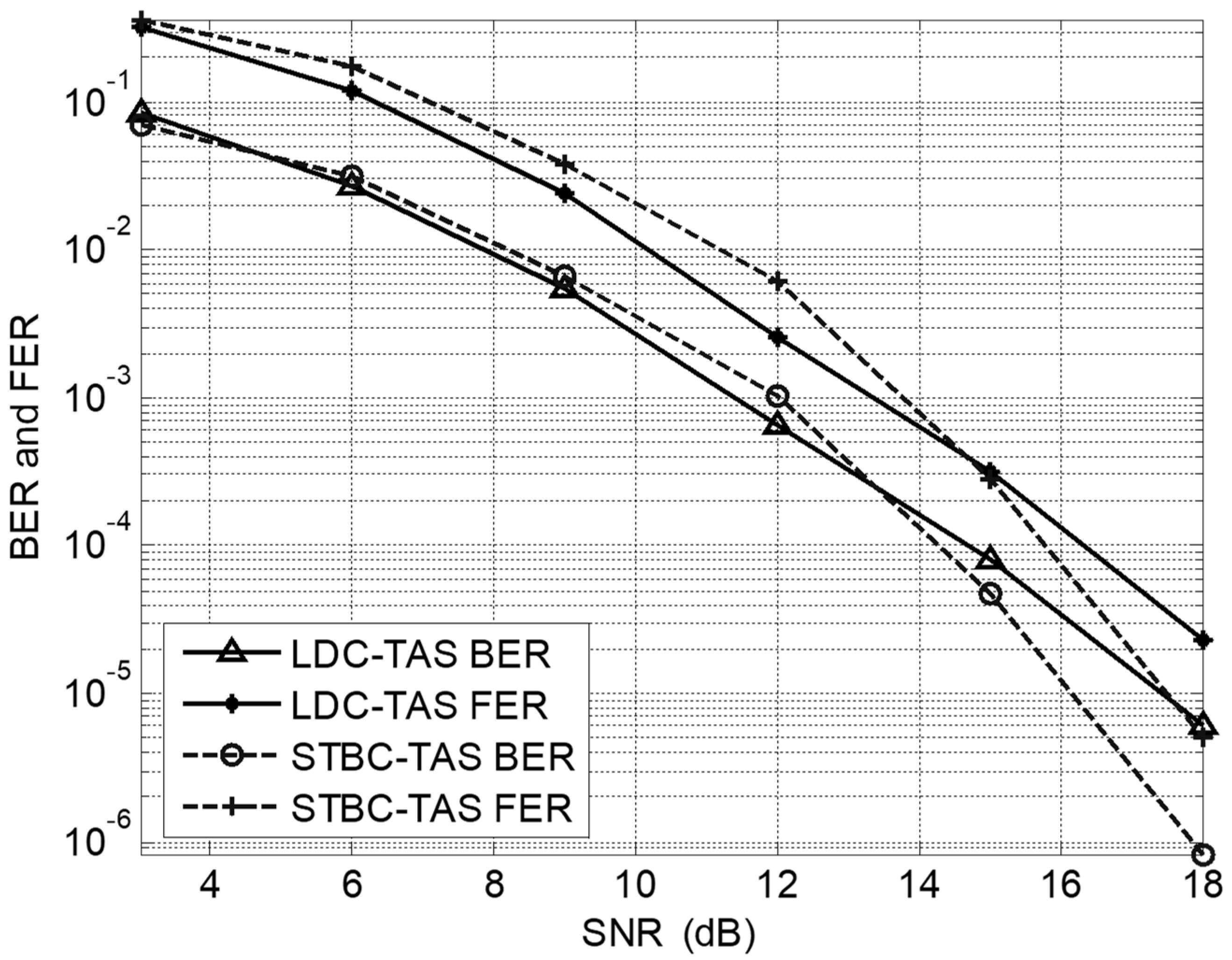
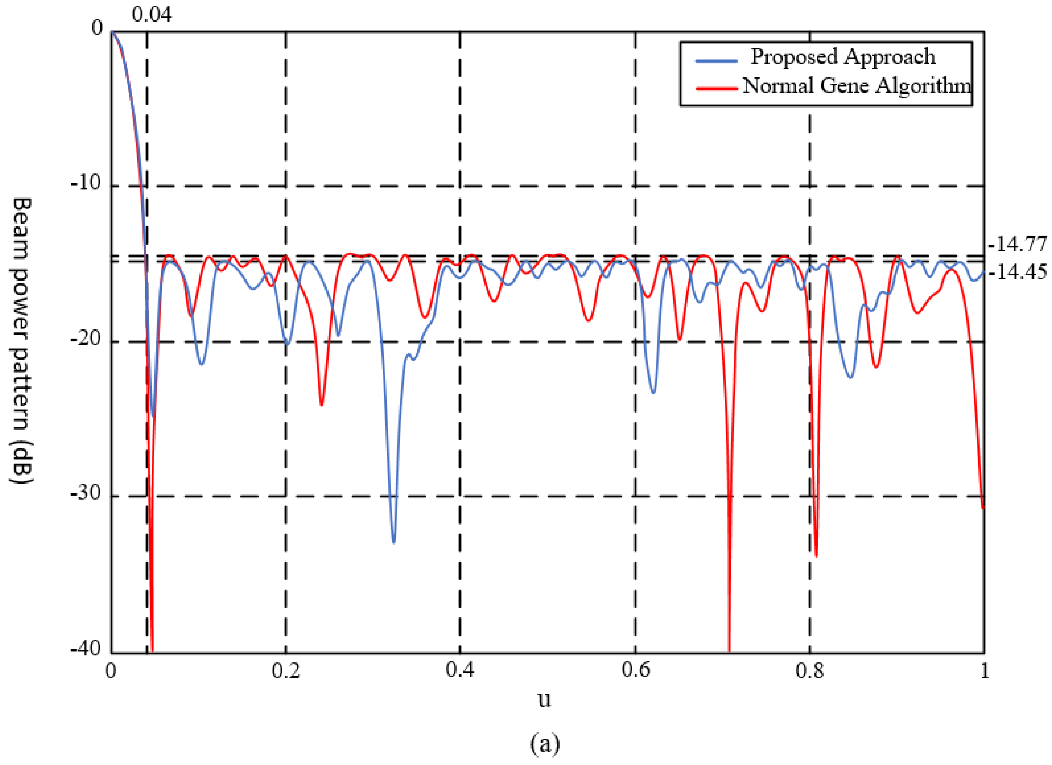
6. Simulation Analyses

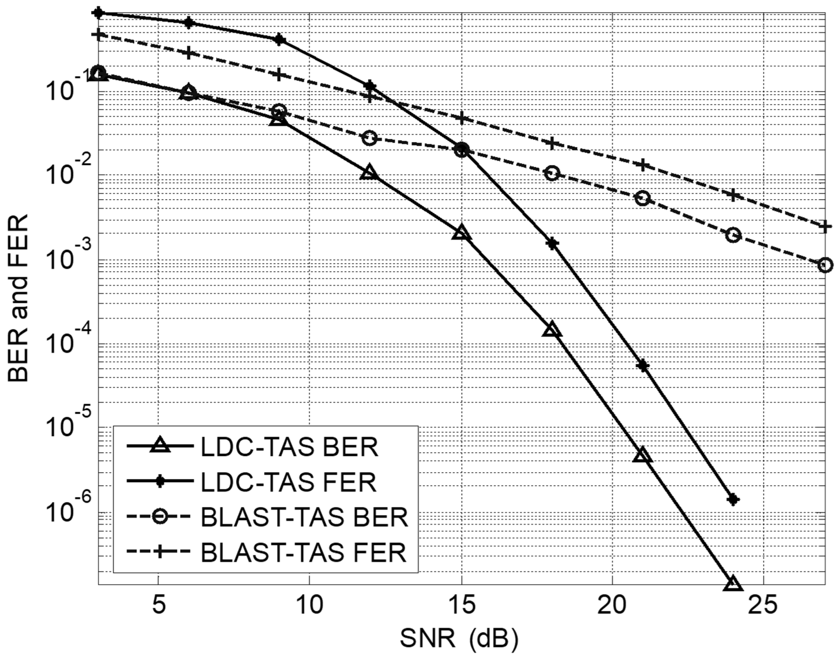
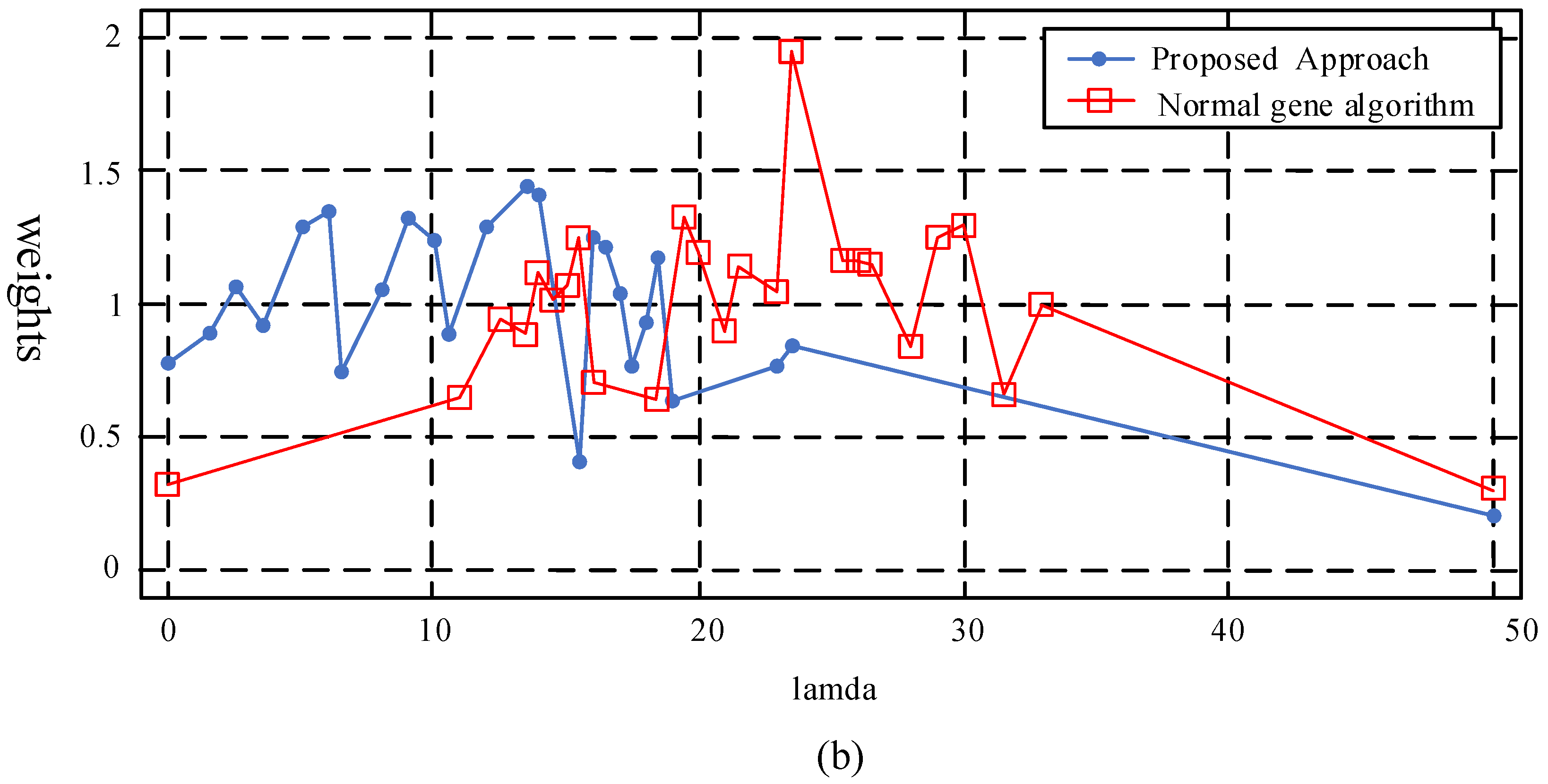
6.1. Result Analyses

To assess the advantage and effectiveness of the proposed algorithm, several different experiments instances were monitored and explored. In the following part, to assess the flexibility and effectiveness of the presented approach, the specific numerical results are shown and compared with some reference ways (obtainable from the literature [20,21,22]). In the first example, to minimize the maximum side lobes level (Φslp) via the changing element weight was solved. As for the problem, in [22] the combining process was utilized to the linear matrix of 25 isotropic elements D = 50 λ in length. The power weight parameters were set to change inside the range [0.2, 2.0] and the parameter ustart was fixed to 0.04 to compare the performances of the results achieved via normal GA with the IGA optimization.
As far as this application is concerned, we supposed that the length of this array was dispersed in N = 100(λ/2)-spaced steps via pushing the specific number of the elements M, equals to 25. Such that, the architectures of those series of the chromosome results as below:
ξ ¯ = { ω 0 , , ω k , , ω N 1 } , b k = 1   k = 0 , ,   N 1 , M = 25 .
Figure 6 shows the comparison between the element, the BP, and the position layout of such arrays. The most optimal result is the array with a side lobe peak value located at Φslp = −14.77 dB. However, to the authors’ knowledge, the best threshold for the side-lobes level obtained in article [26] was just −14.45 dB approximately, and uml = 0.191 was the width of the half-beam width.
However, then as far as the main lobe width is concerned, one of the most optimal results was the specific array with a beam pattern (BP), which was characterized by a side lobe peak value being Φslp = −14.67 dB and the main-lobe width value uml = 0.0204.
In order to meet the accuracy and completeness, Figure 7 illustrated the specific collection of those best results achieved behind the running of the presented method to highlight an obtainable trade-off among the main-lobe width and the side-lobe peak value. As a reminder, it has to be pointed out that, although the side-lobe decrease of approximately 0.2 dB could be lower than the errors’ number in the real phased array, these obtained results are pretty good due to the closeness to the theoretically optimal value. For the convenience to the comparison, this figure also shows the outcome with the procedure based on the SA (Simulated Annealing).
In this testing part, the optimizing process of the quantity of these sensors and of the specific length of the array using a fixed beam pattern shape was thought about. The expected pattern was the same as in [11,16] and illustrated in Table 1 below.
The algorithm proposed in the paper intended to work, firstly, as every node writes the local interference power value into the HELLO message, and then broadcasts it to its neighbors.
At last, the isophoric matrices [19] were also thought about as well. In this instance, the power weights of these array elements were statically set (wk; k = 0, 1, 2, 3, …, N − 2, N − 1) and an optimization procedure took these array element positions into account. Figure 8 draws the beam pattern and the specific location position layout in contact with the best optimal ways, according to these peak values of the minimum side-lobe level (Φslp = −13.06 dB as well as uml = 0.0170; IGA (a)) and according to the optimal trade-off among the side-lobe level value and those main-lobe widths (Φslp = −12.32 dB as well as uml = 0.0126; IGA (b)), achieved via the ways of those IGA-based methods. These specific characters of the array synthesized using the SA-based procedure are given (Φslp = −12.07 dB as well as uml = 0.0133; SA).
Due to the random character of the algorithm proposed in this article, the statistical factors that are relevant to the simulations collection were assessed. Table 2 offers all the values over the best, the worst, the average resulting values, and the standard deviation values according to the number of these elements, the minimum peak value of the side-lobe and these values of the main-lobe width. It is beneficial to see that the filling percentage is lower than the value obtained from the paper [7,8] and the side-lobe peak value at all times.
In summary, it could be highlighted that some specific taking-away of the symmetry restrictions significantly improves its performances, indeed (these symmetrical arrays were concerned inside the literatures [7,8]).

6.2. Complexity Analyses

To evaluate this algorithm, a specific complexity for this method was given in detail in the following part, which is concerned only with the multiplying times of the complexity complex, and the classical matrix operational way. As far as a same set of the parameters of a mobile channel is concerned, it is enough to only analyze one combination of the channel parameters such as H in detail.
In the criterion of the max–min-post-SNR, without considering the operation time of H s ¯ , H s ˜ = H s ¯ χ is a matrix multiplication of order N r T × N T and N T × Q , the multiplying times is N r N Q T 2 , the multiplying times in H ˜ j H H ˜ j 1 is Q 2 N r T , and the inversion times of the Q × Q matrix by the Gauss-Jordan method are about 0.5 Q 3 + 0.5 Q 2 , so the total complexity is N r N Q T 2 + T Q 2 N r + 0.5 Q 3 + 0.5 Q 2 .

7. Conclusions

The coming 5G systems need a reliable and safe mobile communication link with a specific large capacity using much easier and cheaper methods. Since the LDCS meet the information-theoretic optimality property and the selection for the transmitting antennae offers the additional order for the diversity, so the LDC-TAS system is introduced in the paper firstly. Contrasted to a multiple antenna-fading channel, the LDC-TAS system is a simple and cheap way to achieve the diversity advantage, and to maintain the high rate for transmission. Authors educed the specific criteria for the antenna selection when the ZF receiver was utilized as well as investigated it by the computer numerical simulations. Finally, the computing simulation results show that this specific max–min-post-SNR criterion, which is specially produced for the ZF receiver, outperforms some other criteria [19,20]. Moreover, LDC-TAS has the more significant diversity advantage than BLAST-TAS under the same spectral efficiency and is better than STBC-TAS inside the low SNR environment as well.
Once the M antennae are selected through the max–min-post-SNR criterion for the selection, a novel linear antenna synthesis for these linear dispersion codes on the basis of an innovative HYBRID genetic algorithm has been presented and evaluated. The restricted side-lobes class, the width of the main-lobe, as well as the shaped specific beam pattern are contemporarily concerned via maximizing a pretty suitable cost function through the innovative advanced genetic-algorithm-based algorithm. The algorithm presented in the article is able to offer flexibility and a simple insertion of the a priori knowledge under small computing pressure. Furthermore, it is very important that some extensions of the presented approach, which do not have an obvious increase in the algorithm complexity, could still be true.

Author Contributions

J.W. designed the measurement scheme, carried out the simulations, and wrote the paper; N.Z. supervised the work, arranged the architecture, and contributed to the writing of the paper; and Z.Y., B.L. and T.M.S. performed the field test and analyzed the data.

Funding

This research was financially supported via Project of the National Natural Science Foundation of China (61402069), the 2017 Project of the Natural Science Foundation of Liaoning province (20170540059), the General project of Liaoning education department in 2016(2016J205).

Acknowledgments

The authors would like to thank the journal, the anonymous referees, Chief-Editor, and support Editors for their constructive advice and academic propositions which have helped to improve the quality of our current research work.

Conflicts of Interest

The authors declare no conflict of interest.

References

  1. Santhanam, T.; Padmavathi, M.S. Comparison of K-Means clustering and statistical outliers in reducing medical datasets. In Proceedings of the IEEE International Conference on Science, Engineering and Management Research (ICSEMR), Chennai, India, 27–29 November 2014. [Google Scholar]
  2. Zhenyu, M.; Jeng-Shyang, P.; Huarong, X. Quasi-Affine, Transformation Evolutionary (QUATRE) algorithm: A cooperative swarm based algorithm for global optimization. Knowl. Based Syst. 2016, 109, 104–121. [Google Scholar]
  3. Jinpeng, W.; Nianyu, Z.; Yuncui, Z.; Ping, L. Study on downlink performance of multiple access algorithm based on antenna diversity. ICIC Express Lett. 2015, 9, 1221–1225. [Google Scholar]
  4. Aishwarya, S.; Anto, S. A medical decision support system based on genetic algorithm and least square support vector machine for diabetes disease diagnosis. Int. J. Eng. Sci. Res. Technol. 2014, 3, 4042–4046. [Google Scholar]
  5. Hassibi, B.; Hochwald, B.M. High-Rate codes that are linear in space and time. IEEE Trans. Inf. Theory 2002, 48, 1804–1824. [Google Scholar] [CrossRef]
  6. Dorsey, W.M.; Coleman, J.O. Uniform circular array pattern synthesis using second-order cone programming. IET Microw. Antennas Propag. 2015, 9, 723–727. [Google Scholar]
  7. Weile, D.S.; Michielssen, E. Integer coded Pareto genetic algorithm design of constrained antenna arrays. Electron. Lett. 1996, 32, 1744–1745. [Google Scholar] [CrossRef]
  8. Trucco, A.; Murino, V. Stochastic optimization of linear sparse arrays. IEEE J. Ocean. Eng. 1999, 24, 291–299. [Google Scholar] [CrossRef]
  9. Wang, J.; Zhang, S.; Zhang, J. Multi-Hop Maimal Ratio Combining (MHMRC) diversity based on virtual cellular network. J. Jilin Univ. 2011, 41, 533–536. [Google Scholar]
  10. Chen, K.; He, Z.; Han, C. A modified real GA for the sparse linear array synthesis with multiple constraints. IEEE Trans. Antennas Propag. 2006, 54, 2169–2173. [Google Scholar]
  11. RaviKumar, G.; Ramachandra, G.A.; Nagamani, K. An efficient feature selection system to integrating SVM with genetic algorithm for large medical datasets. Int. J. Adv. Res. Comput. Sci. Softw. Eng. 2014, 4, 272–277. [Google Scholar]
  12. Shengbo, E.L.; Renjie, L.; Wang, J.; Xiaosong, H.; Cheng, B.; Keqiang, L. Stabilizing periodic control of automated vehicle platoon with minimized fuel consumption. IEEE Trans. Transp. Electr. 2017, 3, 259–271. [Google Scholar]
  13. Zou, Q.-F.; Tan, X.-Z.; Liu, M.; Ma, L. Low complexity frequency domain iterative equalization based on minimum mean square error for single carrier systems. Jilin Daxue Xuebao 2015, 45, 2062–2068. [Google Scholar]
  14. Ghrayeb, A.; Duman, T.M. Performance analysis of MIMO systems with antenna selection over quasi-static fading channels. IEEE Trans. Veh. Technol. 2003, 52, 281–288. [Google Scholar] [CrossRef]
  15. Chen, J.; Li, J.; Yang, S.; Deng, F. Weighted optimization-based distributed Kalman filter for nonlinear target tracking in collaborative sensor networks. IEEE Trans. Cybern. 2017, 1, 1–14. [Google Scholar] [CrossRef] [PubMed]
  16. Santhanam, T.; Padmavathi, M.S. Application of K-Means and genetic algorithms for dimension reduction by integrating SVM for diabetes diagnosis. Procedia Comput. Sci. 2015, 8, 76–83. [Google Scholar] [CrossRef]
  17. Chu, S.-C.; Tsai, P.-W.; Pan, J.-S. Cat swarm optimization. In PRICAI 2006: Trends in Artificial Intelligence; Springer: Berlin, Germany, 2006; pp. 854–858. [Google Scholar]
  18. Su, S.; Qu, D.; Li, L.; Jiang, T. Invertible subset QC-LDPC codes for PAPR reduction of OFDM signals. IEEE Trans. Broadcast. 2015, 61, 290–298. [Google Scholar]
  19. Leeper, D.G. Isophoric arrays—Massively thinned phased arrays with well-controlled sidelobes. IEEE Antennas Propag. Mag. 1999, 47, 1825–1835. [Google Scholar] [CrossRef]
  20. Tiwari, R.; Singh, M.P. Correlation-Based attribute selection using genetic algorithm. Int. J. Comput. Appl. 2010, 4, 28–34. [Google Scholar] [CrossRef]
  21. Ratnakar, S.; Rajeshwari, K.; Rose, J. Prediction of heart disease using genetic algorithm for selection of optimal reduced set of attributes. Int. J. Adv. Comput. Eng. Netw. 2013, 1, 51–55. [Google Scholar]
  22. Chai, E.; Shin, K. Low-Overhead control channels in wireless networks. IEEE Trans. Mob. Comput. 2015, 14, 2303–2315. [Google Scholar] [CrossRef]
  23. Wang, J.; Cao, F.; Zou, N. Multi carrier system joint receiving method based on MAI and ICI. Jilin Daxue Xuebao 2018, 41, 301–305. [Google Scholar]
  24. Sumit, B.; Praveen, P.; Pillai, G.N. SVM based decision support system for heart disease classification with integer-coded genetic algorithm to select critical features. In Proceedings of the World Congress on Engineering and Computer Science, San Francisco, CA, USA, 22–24 October 2008. [Google Scholar]
  25. Hu, M.; Li, Y.; Lu, X.; Zhang, H. Tone reservation to minimize nonlinearity impact on OFDM signals. IEEE Transp. Veh. Technol. 2015, 64, 4310–4314. [Google Scholar] [CrossRef]
  26. Yilmaz, N.; Inan, O.; Uzer, M.S. A new data preparation method based on clustering algorithms for diagnosis systems of heart and diabetes diseases. J. Med. Syst. 2014, 38, 48. [Google Scholar] [CrossRef] [PubMed]
  27. Guido, R.; Conforti, D. A hybrid genetic approach for solving an integrated multi-objective operating room planning and scheduling problem. Comput. Oper. Res. 2017, 87, 270–282. [Google Scholar] [CrossRef]
  28. Qiu, X.; Sha, X.-J.; Mei, L. Hybrid carrier CDMA multi-antenna system based on weighted-type fractional fourier transform. Jilin Daxue Xuebao 2013, 43, 218–222. [Google Scholar]
  29. Guillermo, D.; Rey, P.A.; Wolff, P. Solving the operating room scheduling problem with prioritized lists of patients. ANN Oper. Res. 2016, 258, 395–414. [Google Scholar]
  30. Yuan, R.; Guangchen, B. Determination of optimal SVM parameters by using genetic algorithm/particle swarm optimization. J. Comput. 2010, 5, 1160–1169. [Google Scholar]
  31. Patil, B.M.; Joshi, R.C.; Toshniwal, D. Impact of K-Means on the performance of classifiers for labeled data. In International Conference on Contemporary Computing; Springer: Berlin, Germany, 2010; Volume 94, pp. 423–434. [Google Scholar]
  32. Velmurugan, T. Efficiency of K-Means and K-Medoids algorithms for clustering arbitrary data points. Int. J. Comput. Technol. Appl. 2012, 3, 1758–1764. [Google Scholar]
  33. Chinneck, J.W. Practical Optimization: A Gentle Introduction. 2014. Available online: http://www.sce.carleton.ca/faculty/chinneck/po/Chapter20.pdf (accessed on 21 December 2018).
  34. Isa, N.A.M.; Wan Mamat, W.M.F. Clustered-Hybrid multilayer perceptron network for pattern recognition application. Appl. Soft Comput. 2011, 11, 1457–1466. [Google Scholar]
  35. Anuja Kumari, V.; Chitra, R. Classification of diabetes disease using support vector machine. Int. J. Eng. Res. Appl. 2013, 3, 1797–1801. [Google Scholar]
  36. Chikh, M.A.; Saidi, M.; Settouti, N. Diagnosis of diabetes diseases using an Artificial Immune Recognition System2 (AIRS2) with fuzzy K-Nearest neighbor. J. Med. Syst. 2012, 36, 2721–2729. [Google Scholar] [CrossRef] [PubMed]
  37. Abadi, A.; Rajabioun, T.; Ioannou, P. Traffic flow prediction for road transportation networks with limited traffic data. IEEE Trans. Intell. Transp. Syst. 2015, 16, 653–662. [Google Scholar] [CrossRef]
  38. Lv, Y.; Duan, Y.; Kang, W.; Li, Z.; Wang, F.-Y. Traffic flow prediction with big data: A deep learning approach. IEEE Trans. Intell. Transp. Syst. 2015, 16, 865–873. [Google Scholar] [CrossRef]
  39. Zhang, L.; Ma, J.; Zhu, C. Theory modeling and application of an adaptive Kalman filter for short-term traffic flow prediction. J. Inf. Comput. Sci. 2012, 9, 5101–5109. [Google Scholar]
  40. Faruk, D.Á. A hybrid neural network and ARIMA model for water quality time series prediction. Eng. Appl. Artif. Intell. 2010, 23, 586–594. [Google Scholar] [CrossRef]
  41. Chen, C.-F.; Lai, M.-C.; Yeh, C.-C. Forecasting tourism demand based on empirical mode decomposition and neural network. Knowl. Based Syst. 2012, 26, 281–287. [Google Scholar] [CrossRef]
  42. Bauza, R.; Gozalvez, J. Traffic congestion detection in large-scale scenarios using vehicle-to-vehicle communications. J. Netw. Comput. Appl. 2013, 36, 1295–1307. [Google Scholar] [CrossRef]
  43. De Ridder, K.; Kumar, U.; Lauwaet, D.; Van Looy, S.; Lefebvre, W. Kalman filter-based air quality forecast adjustment. In Air Pollution Modeling and Its Application XXII; Springer: Dordrecht, The Netherlands, 2013; pp. 177–181. [Google Scholar]
  44. Pappula, L.; Ghosh, D. Linear antenna array synthesis using cat swarm optimization. AEU Int. J. Electr. Commun. 2014, 68, 540–549. [Google Scholar] [CrossRef]
  45. Basak, A.; Pal, S.; Das, S.; Abraham, A.; Snasel, V. A modified invasive weed optimization algorithm for time-modulated linear antenna array synthesis. In Proceedings of the IEEE Congress on Evolutionary Computation, Barcelona, Spain, 18–23 July 2010. [Google Scholar]
  46. Mahanti, G.K.; Chakraborty, A.; Das, S. Phase-Only and amplitude-phase only synthesis of dual-beam pattern linear antenna arrays using floating-point genetic algorithms. Prog. Electromagn. Res. 2007, 68, 247–259. [Google Scholar] [CrossRef]
  47. Baskar, S.; Alphones, A.; Suganthan, P.N. Genetic algorithm based design of a reconfigurable antenna array with discrete phase shifter. Microw. Opt. Technol. Lett. 2005, 45, 461–465. [Google Scholar] [CrossRef]
  48. Mitilineos, S.A.; Mougiakos, K.S.; Thomopoulos, S.C. Design and optimization of ESPAR antennas via impedance measurements and a genetic algorithm (antenna designer’s notebook). IEEE Antennas Propag. Mag. 2009, 51, 118–123. [Google Scholar] [CrossRef]
  49. Maltsev, A.; Sadri, A.; Pudeyev, A.; Bolotin, I. Highly directional steerable antennas: High-gain antennas supporting user mobility or beam switching for reconfigurable backhauling. IEEE Veh. Technol. Mag. 2016, 11, 32–39. [Google Scholar] [CrossRef]
  50. Majumdar, B.; Esselle, K.P. Fixed frequency broadside-endfire beam steerable antennas. Electr. Lett. 2016, 21, 1282–1284. [Google Scholar] [CrossRef]
  51. Zhang, J.; Wang, J.; Zhang, S. Pseudorange measurement method based on AIS signals. Sensors 2017, 5, 22. [Google Scholar] [CrossRef] [PubMed]
Figure 1. Transmit antenna selection for linear dispersion codes.
Symmetry 11 01176 g001
Figure 2. Performance of linear dispersion code transmitting antenna selection (LDC-TAS) vs. space–time block code (STBC)-TAS.
Symmetry 11 01176 g002
Figure 3. Performance of LDC-TAS vs. Bell Labs layered space time (BLAST)-TAS.
Symmetry 11 01176 g003
Figure 4. The geometry of the linear array.
Symmetry 11 01176 g004
Figure 5. Flowchart of the innovative genetic algorithm.
Symmetry 11 01176 g005
Figure 6. Optimization of the element power weights—(a) beam pattern (BP) with a side-lobe peak value of −14.77 dB; and (b) positions and power weights of those array elements.
Symmetry 11 01176 g006aSymmetry 11 01176 g006b
Figure 7. Optimization of the element power weights—peak side-lobe value level as a specific function of the main-lobe width ((dB) units; simulated innovative genetic algorithm (IGA); O: Simulated SA).
Symmetry 11 01176 g007
Figure 8. Optimization of the element location positions and power weights—optimal combinations for isophoric arrays. (a) Beam patterns; and (b) array placement.
Symmetry 11 01176 g008
Table 1. Beam pattern restrictions.
RegionBP Amplitude Factors
0 < μ ≤ 0.04180 dB
0.0419 < μ ≤ 0.307−13.368 dB
0.308 < μ ≤ 0.446−26.876 dB
0.447 < μ ≤ 0.79713.395 dB
0.798 < μ ≤ 10 dB
Table 2. Statistical behavior of the quantity of those active elements, side lobe peak value as well as the width of main-lobe behind several dozens of the procedure implement.
Quantity of the Active Elements (M)
The BestThe WorstAverageStd. Dev
149 (73.5%)156 (76.5%)148.9 (74.8%)1.0358
Side-Lobe Peak Value (Φslp; dB)
The BestThe WorstAverageStd. Dev
−23.19−22.61−22.910.2322
Main-Lobe Width (uml)
The BestThe WorstAverageStd. Dev
0.00500.00520.00508~0
Note: In this table, the word “Std. Dev” means “the standard deviation values”.

