1. Introduction
Cable-driven manipulators (CDMs) are a special class of mechanisms in which cables are employed as the driving elements. Compared to the conventional rigid robotic manipulators, CDMs have advantages of large workspace, low moving mass, high payload-to-weight ratio, and variable stiffness. As such, they have been applied in inspection and repair [
1,
2,
3], human-robot interaction [
4,
5,
6], moving and lifting payloads [
7,
8,
9] and wearable robots [
10,
11,
12,
13,
14]. Since cables have unilateral driving properties, i.e., can pull but cannot push, the number of driving cables in a CDM is greater than the number of its Degree-of-Freedom (DOF), yielding redundant actuation. Thus, there exist an infinite number of cable tension distribution settings for any given pose of a CDM. As the stiffness of a CDM can be regulated by adjusting the cable tensions [
15], a redundantly actuated CDM has the merit of variable stiffness for safe human-robot interactions. Therefore, a CDM is a promising candidate of collaborative robots to perform various manipulation tasks in human environment [
16,
17].
In the last decades, the design [
18,
19], kinematics [
20], workspace [
21,
22], motion control [
23] and stiffness [
24,
25,
26] of CDMs have been studied by many researchers. For the issue of cable tension distribution, some researchers studied the cable tension distribution of a CDM to minimize a p-norm (such as 1-norm, or 2-norm) of the tensions, aiming to reduce the energy consumption [
27,
28,
29,
30,
31,
32]. In [
33], an analytical method is proposed to minimize magnitude sum of cable tensions for a completely restrained 6-DOF CDM, in order to obtain the optimal tension distribution for lowest energy consumption. However, such a method is not applicable for CDMs with more than one redundant cable. In [
34], a cable tension distribution method is proposed to control the cable-driven platform on a given trajectory, which is formulated as a constrained optimization problem to minimize the 2-norm of the cable tensions. Two algorithms based on interval analysis and gradient-based optimizer are investigated to compute the optimal cable tension solutions. However, these norm-based optimization methods would generally suggest the results being close to the lower tension limits. This potentially resulted in low robot stiffness and left the cable tend to be slack. To solve this issue, in [
35], a non-iterative method is proposed to find out the safe tension distributions being away from the tension limits. However, this method is computational intensive when the number of cables increases. In [
36], the issue of stiffness-oriented cable tension distribution is studied and a gradient projection based method is developed to regulate the stiffness of a CDM by adjusting cable tensions. However, this method employs the determinant of the stiffness matrix as the cost function, rather than all entries of the stiffness matrix. It is difficult to achieve the desired stiffness accurately. In summary, the issue of the cable tension distribution for accurately achieving a desired feasible stiffness of a CDM has not been addressed well.
In this paper, we focus on the issue of stiffness-oriented cable tension distribution for a symmetrical
6-cable-driven spherical joint module (6-CSJM), which can be employed as a fundamental block for building modular CDMs. For such a 6-CSJM, due to its redundant actuation, three cables are enough for position control, and the remaining three cables can be utilized for stiffness regulation. To increase the range of stiffness regulation, a
variable stiffness device (VSD) is designed to connect to the driving cable serially. Compared to other design [
18], this VSD is fixed on the platform, rather than directly attached to the midway of the hanging cables. Such VSD arrangement reduces the VSD’s disturbance to the cable tensions effectively. Consequently, the position and stiffness of a 6-CSJM can be regulated simultaneously, such that its position can be controlled by adjusting the three cable lengths, while its stiffness can be controlled by adjusting the remaining three cable tensions. The stiffness model of the 6-CSJM indicates that its stiffness is related to both the geometry change of the 6-CSJM and stiffness of the driving cable with a VSD [
37]. Due to the complexity of the stiffness model, it is difficult to obtain the cable tension distribution from a desired stiffness directly. Hence, we formulate the issue of stiffness-oriented cable tension distribution as a nonlinear constrained optimization problem. The cost function is constructed based on all entries of the stiffness matrix of the 6-CSJM, rather than its determinant. Furthermore, we set safe tension zone for the cable and the VSD to avoid the cable being slack and the tension exceeding the torque limit of the driving motor. A variable elimination technique is proposed to deal with the three equality constraints in the optimization model and the decision variables are significantly reduced from 6 to 3. Since the stiffness model of the 6-CSJM with nonlinear VSDs is complicated, the widely used gradient-based optimization algorithm is not appropriate. Instead, the Complex method is employed, since it merely require cost function values in the optimization process [
38]. The effectiveness of the proposed method is validated by a comprehensive simulation. In summary, the major merit of the proposed stiffness-oriented cable tension distribution method is that it provides an effective way to achieve accurate stiffness regulation and position control simultaneously.
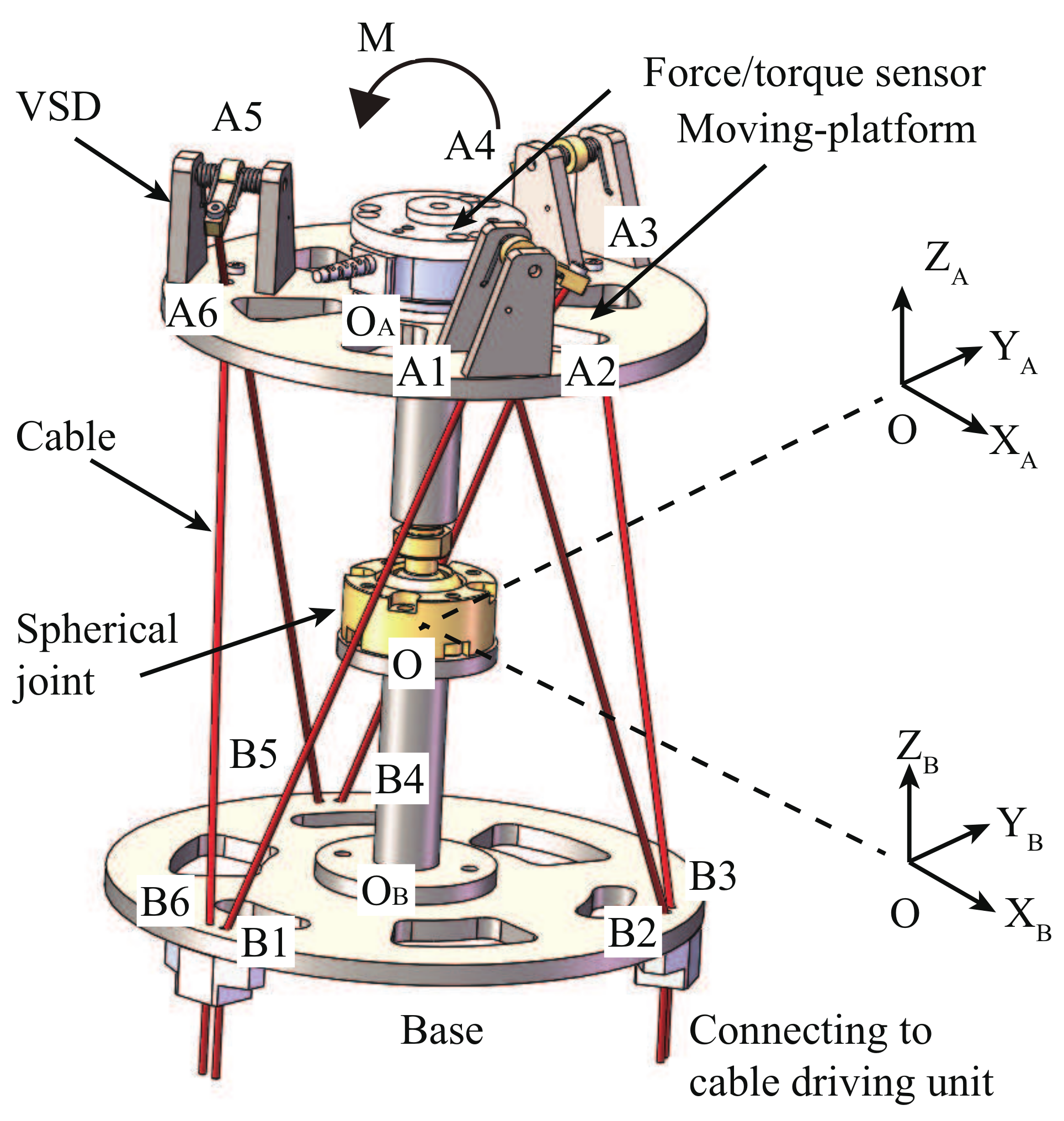
2. Design of the 6-CSJM with VSDs
The cable-driven spherical joint module (CSJM) consists of a moving-platform, a base and a passive spherical joint. The moving-platform is driven by cables. Since the cables can pull but cannot push, for the 3-DOF CSJM, the number of driving cables,
n, should satisfy
[
39]. To have a symmetrical design, six cables are employed in this CSJM. As shown in
Figure 1, there are six small holes on both of the moving-platform and the base for cables passing through, denoted by
and
, respectively. Geometrically,
,
,
and
.
O,
and
are the centers of the passive spherical joint, moving-platform and base plate, respectively, in which
and
. In order to describe the motion, we set the base frame
being attached to the base, and the moving frame
being attached to the moving-platform. When the 6-CSJM is at home pose, the moving-platform is parallel to the base and the two frames coincide with each other.
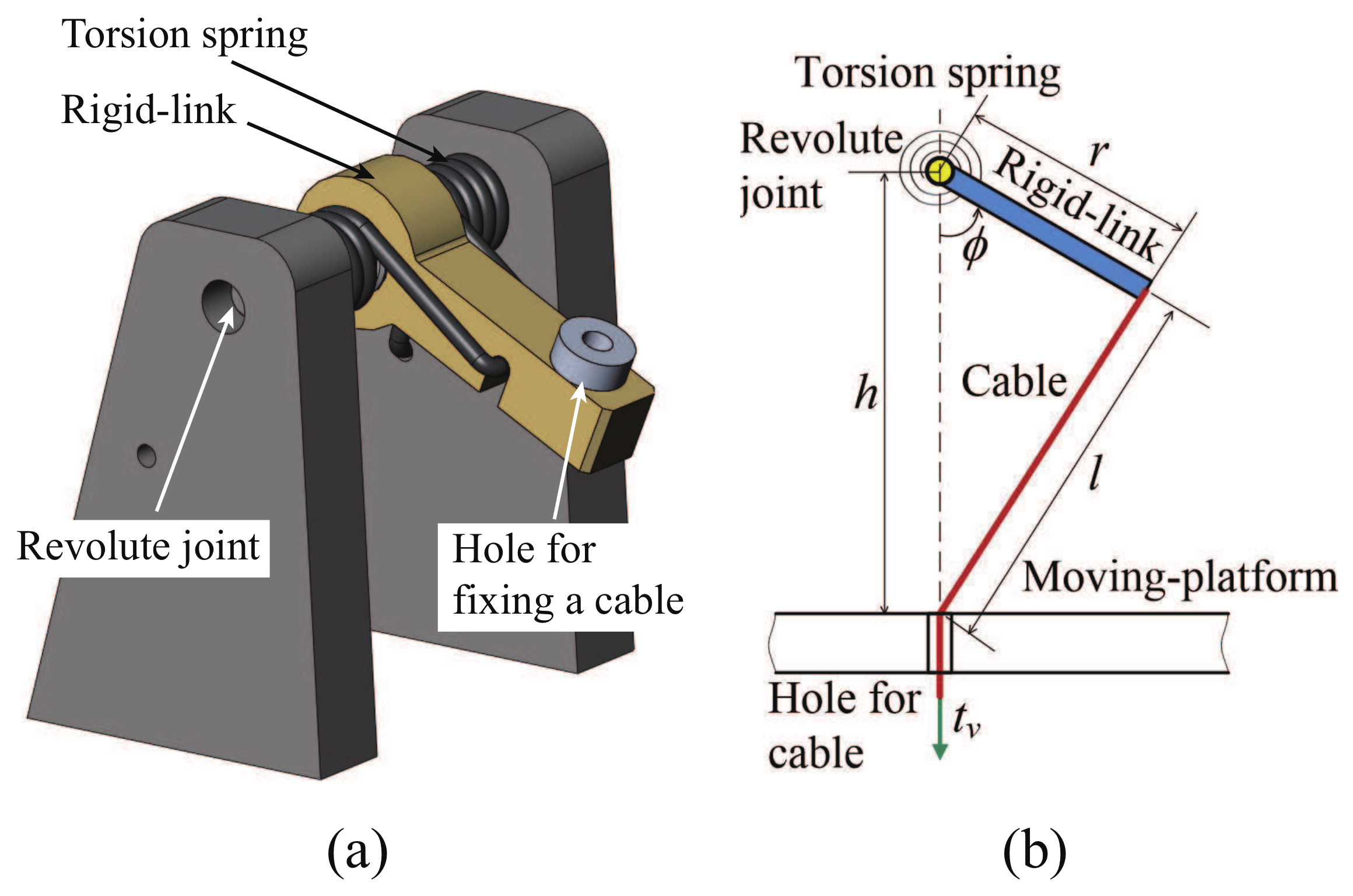
Due to the redundant actuation of the 6-CSJM, three cables are enough for position regulation and the other three cables can be employed for stiffness regulation. Thus, the position and stiffness can be regulated simultaneously. Considering the symmetry of the 6-CSJM, six driving cables are divided into two groups. Cable 1, 3 and 5 are grouped for position regulation, which can be realized by adjusting the cable lengths. Meanwhile, Cable 2, 4 and 6 are grouped for stiffness regulation, which can be realized by adjusting the cable tensions. In order to increase the range of stiffness regulation, a novel VSD is designed and it is connected to the cable in series. The CAD model and kinematic diagram of the VSD are shown in
Figure 2. This VSD is basically a 1-DOF cable-driven mechanism, in which a set of torsional springs with constant stiffness are employed to connect the rotating rigid link to the shaft of the revolute joint. Compared to the other designs [
18], our VSDs are fixed on the platform, rather than directly attached to the midway of the hanging cables. Such design effectively reduces the perturbation to the cable tensions from the gravity of the VSDs.
In this 6-CSJM, three VSDs (VSD 2, 4 and 6) are installed on the top of the moving-platform. Cable 2, 4 and 6 are fixed to VSD 2, 4 and 6, go through the holes , and on the moving-platform, and then go through the holes , and on the base, finally be connected to the cable-driven motors, respectively. Cable 1, 3 and 5 are fixed in the holes , and on the moving-platform, go through the holes , and on the base, finally be connected to the cable-driven motors, respectively. In order to measure the external load applied on the moving-platform, a force/torque sensor is installed on the moving-platform.
3. Stiffness Model of the VSD
As shown in
Figure 2b, the cable length
l in the VSD satisfies
where
h is the height of the revolute joint,
r is the length of the rigid-link and
is the angle of the rigid-link. The cable tension
applied on the VSD satisfies the equilibrium equation of the VSD, hence it can be represented as
where
is the stiffness of the torsional spring and
is the initial value of angle
. In this design,
Nm/rad,
m,
m, and
rad. According to (
1) and (
2), the cable length
l and the cable tension
are both dependent on the angle
. Denote
and
, then the stiffness of the VSD,
, can be represented as
It shows that the stiffness
is also dependent on the angle
. The expression of the
and
are both complicated in terms of
. It is difficult to obtain the explicit solution of
from
. Hence, it is a tough job to obtain exact explicit formulation of
in terms of
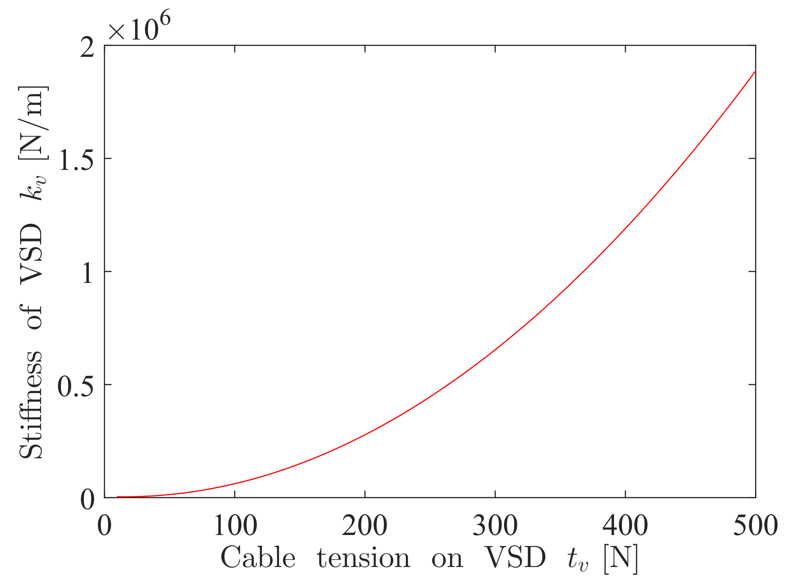
. In order to simplify the calculation, we approximate the expression of
in terms of
by a polynomial (
4), with 95% confidence bounds and
R-square = 0.996, i.e.,
The curve of
with respect to
is shown in
Figure 3, indicating that the stiffness is nonlinear and it increases when the cable tension increases. On the other hand, the displacement of the cable in the VSD,
, can be expressed in terms of
approximately as following
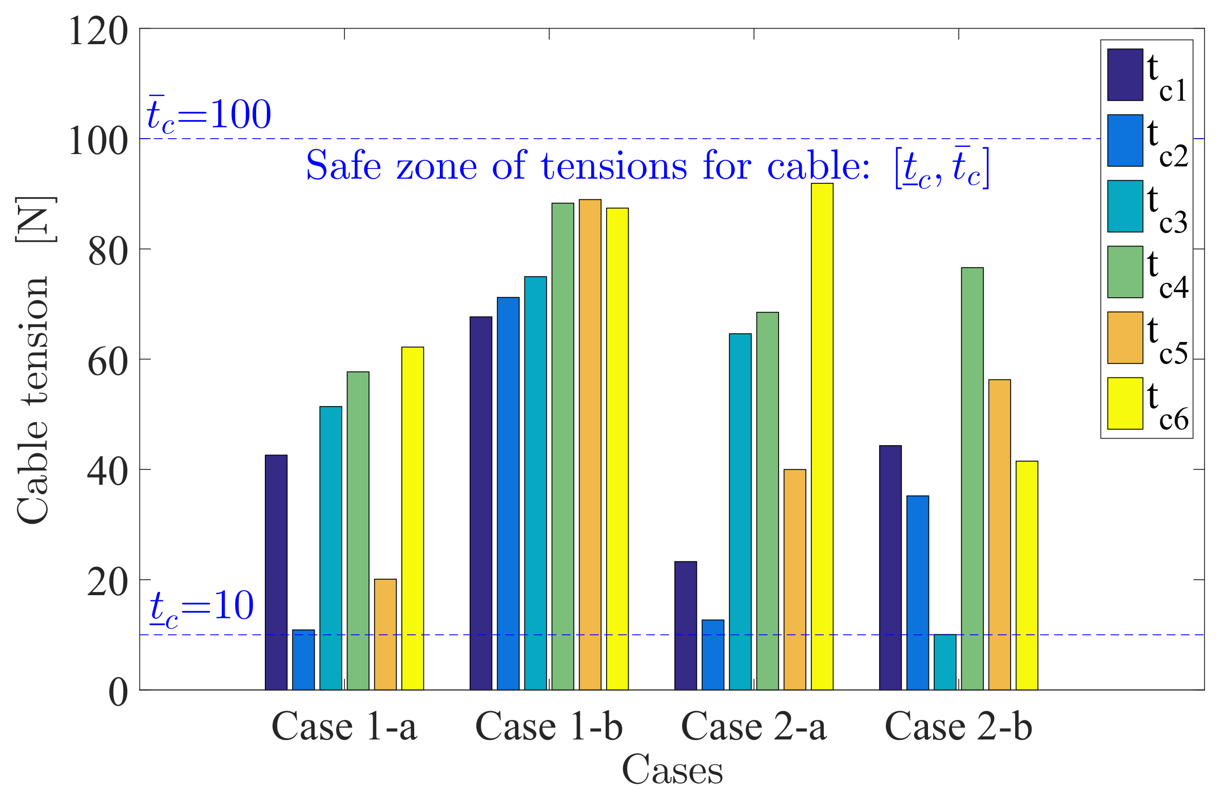
Considering the torque limit of cable driving motor and the tensile strength of the cable, and to avoid the cable being slack, the cable tensions should be limited. Here, we set 10 N N for the cable tension applied on the VSD, terming it as the safe tension zone of the VSD. Similarly, we also set 10 N N as the safe tension zone for the driving cables without connecting to a VSD.
4. Stiffness Model of the 6-CSJM
4.1. Kinematic Analysis of the 6-CSJM
In the 6-CSJM, the moving-platform realizes 3-DOF rotational motions about the spherical joint. The pose of the moving-platform, described by the pose of the moving frame {A} with respect to the base frame {B}, is a rotational matrix
. Thus, the motion of the moving-platform is a curve on
, denoted as
. It satisfies
where
,
and
are the basis of Lie algebra
, and
is the canonical coordinate of
with respect to the basis. Here, we choose
,
and
, then
,
and
represent instantaneous rotations of the moving-platform about the axes
,
and
, respectively, where the operation
is defined as
Since is a vector of the rotational angles, describing the motion of the moving frame {A} with respect the base frame {B}, the velocity of the moving-platform satisfies
As shown in
Figure 1, denote
and
as the position vectors of
and
in frame
, respectively, the vector of the
cable from
to
, denoted as
, satisfies
Here,
can be expressed as
, where
is the position vector of point
in frame
. Define
and
, then
. By differentiating (
9) with respect to time, we have
where
is the angular velocity of the
ith cable in frame
. Dot-multiplying both sides of (
10) by
, we obtain
or the equivalent matrix form as
where
and
. Equation (
12) represents the velocity of the cable elongation in terms of the change rate of the coordinate.
4.2. The Stiffness Model of the 6-CSJM
In this paper, the stiffness of the
ith driving cable
satisfies
, where the stiffness of the cable
N/m. When a driving cable is connected to a VSD, the overall stiffness of the cable with the VSD, denoted as
, satisfies
where
is the stiffness of the VSD.
Denote
as the total load applied to the moving-platform,
as the tension vector of the
ith cable, and
, where
, the static equilibrium equation of the moving-platform is given below
Substituting (
12), i.e.,
, into (
14), we have
where
is called
structure matrix. The differential form of (
15) is given below
According to the analysis above, we have
Here,
is the stiffness matrix of 6-CSJM to be determined,
is a diagonal matrix whose element
represents the stiffness of the
ith
cable, and
is defined by
The diagonal element of
satisfies
if there is a VSD connected to the cable, or
if there is no VSD connected to the cable.
Substituting (
17), (
18) and (
19) into (
16), the stiffness model of the the 6-CSJM is expressed as
The first part
yields
which represents the stiffness caused by the elongation of the cable (with the VSD) and it is a symmetric matrix. The second part
yields
which represents the stiffness caused by the change of the geometry of the 6-CSJM.
5. Stiffness-Oriented Cable Tension Distribution Method
As stated in the prior section, Cable 1, 3 and 5 are employed for position control, while Cable 2, 4 and 6 are employed for stiffness regulation. According to (
9), the desired feasible pose
can be easily realized by adjusting the lengths of Cable 1, 3 and 5. For stiffness regulation, we should adjust the tensions of Cable 2, 4 and 6 to achieve the desired feasible stiffness. However, due to the complexity of the stiffness model (
21), it is difficult to solve the cable tension distribution from the desired feasible stiffness directly. Instead, we formulate the stiffness-oriented cable tension distribution issue as an optimization problem.
5.1. Formulation of the Optimization Model
Denote
as the desired stiffness matrix of the 6-CSJM at a given pose
, and
as the actual stiffness matrix, a desired stiffness matrix is computed with the given cable tensions according to the stiffness model (
21) and an actual stiffness matrix is computed with the actual cable tensions or measured by the equipments. For this issue, we require the actual stiffness matrix to achieve the desired stiffness matrix, hence a scalar,
, is defined to evaluate the distance of the two stiffness matrices.
where all entries of the stiffness matrix are employed, rather than its determinant. Eventually, we define a cost function
, and formulate an optimization model for the stiffness-oriented cable tension distribution issue
where
is the safe tension zone of VSDs, and
is the safe tension zone of cables.
5.2. Elimination of Equality Constraint
The nonlinear optimization model (
25a) has both equality and inequality constraints. Here, a variable elimination technique is proposed to deal with the equality constraints and the decision variables are significantly reduced from 6 to 3. Denote
,
,
, and
, where
is the tension of the
cable, and
is the
column vector of the matrix
. Then we can write (25b) as
The cable tension vector for position control can be represented by
Equation (
27) implies that
is dependent on
. Denote
and
, then the model (
25a) can be written as
Remarkably, (
28a) only contains inequality constraints. In prior works, such optimization model are usually solved by gradient-based methods. However, the derivative of the cost function of this model is complicated and difficult to obtained. Thus, the Complex method is employed as the optimization algorithm to solve this model, since it merely require cost function values.
5.3. Optimization Procedures via Complex Method
When applying the Complex method, there are three decision variables from and six inequality constraints from (28b) and (28c). The procedures are described as following:
- (i)
Formation of the initial Complex: An initial Complex with six vertices , , ⋯, is setup in the feasible region randomly.
- (ii)
Generation of a new complex: The values of the cost function at the vertices are computed. The worst point
, where the cost function obtains the largest value, will be replaced by the mapping point
. In this way, a new Complex is generated. Here, the mapping point
is computed by
where
is the center of the other 5 points except the worst point
, and
is the
reflection factor. The initial value of
. If
is not in the feasible region, it should be computed again with
, while its minimum value
.
- (iii)
Condition of loop stopping: If the
error tolerance,
, the iterative procedure will terminate, and we go to (iv). Otherwise, we go back to (i). Here,
is defined as
In (
30),
is the value of the cost function at the vertex of the current Complex.
is the best point, such that its cost function has the minimum value.
- (iv)
Finalization of optimal solution: The best point is selected as the optimal solution . From here, the optimal cable tension distribution is obtained for the desired feasible stiffness.
- (v)
Validation of stiffness model: The actual stiffness
is computed by substituting the optimal cable tensions
into the stiffness model (
21). The error
is defined to evaluate the difference between
and
,
where
represents the
Frobenius norm of the matrix.
6. Simulation
In order to validate the proposed method, a comprehensive simulation is carried out. The dimension parameters of the 6-CSJM for simulation are given by m, m, m, m, m, and m.
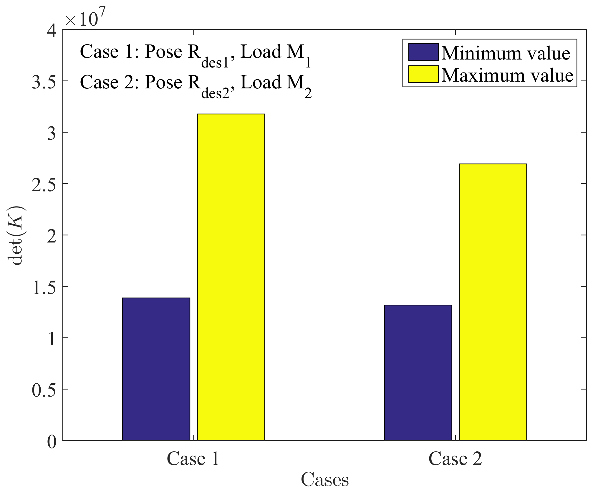
6.1. Simulation Cases
Firstly, we consider two cases of the 6-CSJM with different poses and loads, i.e., Case 1 with desired pose and load , Case 2 with desired pose and load . The desired poses and are given by and , respectively. The load represents the external moment at pose , which are given by Nm and Nm, respectively.
Since the stiffness of the 6-CSJM is a
matrix, we employ the determinants of the stiffness matrices to evaluate the ranges of the stiffness. The result is shown in
Figure 4, suggesting the ranges of the stiffness of the 6-CSJM are adequate for regulation.
Followed by this, we choose two desired feasible stiffness matrices for each of the above two cases and generate four sub-cases, as shown in
Table 1, so that we can evaluate the effectiveness of our method for the 6-CSJM at different poses, with different loads and desired stiffness.
Taking Case 1-a as an example, for the position regulation, the desired pose
can be realized by adjusting the lengths of Cable 1, 3 and 5, where the lengths of Cable 1, 3 and 5 can be computed according to (
9), i.e.,
m,
m and
m. For the stiffness regulation, firstly, the structure matrix
for pose
is obtained by the definition
Subsequently, according to the proposed method in the prior Section, we obtain the optimal cable tensions
N. In the simulation, the corresponding actual stiffness
is computed by the optimal cable tensions according to the stiffness model (
21) and its error with the desired stiffness are listed in
Table 1. The simulation of the other cases are conducted in the similar way as Case 1-a. The values of optimal cable tensions for the four sub-cases are shown in
Figure 5, which illustrates that they are all in the safe tension zone. The actual stiffness and errors of the four sub-cases are all listed in
Table 1.
6.2. Discussion
The stiffness model (
21) is too complicated to solve the cable tension distribution from the desired feasible stiffness directly. Hence we formulate the stiffness-oriented cable tension distribution issue as a constrained optimization problem. Most of the previous research works employ the determinant of the stiffness matrix as the cost function, so that the desired stiffness cannot be achieved accurately. In this paper, we employ all entries of the stiffness matrix to construct the cost function, which is more effective and accurate for stiffness regulation. Besides, we reduce the number of the decision variables from 6 to 3, by eliminating the equality constraints of the optimization model. To solve the nonlinear optimization model, we employ the Complex method to obtain the optimal cable tensions for the desired stiffness. In the simulation, the optimal cable tensions are obtained by using the proposed method, under four sub-cases with different poses, loads and desired stiffness matrices. The result shows that the cable tensions are all in the safe tension zones
(
Figure 5), and each entry of the actual stiffness matrix
is very close to that of desired stiffness matrix
(
Table 1). Hence, the presented method is effective to solve the issue of stiffness-oriented cable tension distribution for the 6-CSJM.
7. Conclusions
In this paper, we focus on the issue of stiffness-oriented cable tension distribution for a symmetrical 6-CSJM, which is designed as a fundamental building block for building modular CDMs. For the 6-CSJM, three cables are enough to regulate position by adjusting the cable lengths, and the remaining three cables can be employed to regulate stiffness by adjusting the cable tensions. That means the position and stiffness can be regulated simultaneously. However, it is difficult to solve the cable tensions from the desired stiffness directly. Instead, we formulate this issue as a nonlinear optimization model with equality and inequality constraints. In order to obtain accurate solution for the issue, all the entries of the stiffness matrix is employed to construct the cost function of the optimization model, rather than its determinant. Furthermore, as it is troublesome to handle equality constraints in an non-linear optimization problem, a variable elimination technique is proposed to deal with the three equality constraints in the optimization model and the decision variables are significantly reduced from 6 to 3. The Complex method is imployed to search for the optimal cable tension distribution for a desired stiffness matrix. A comprehensive simulation is conducted to verify the effectiveness of the proposed method, with different poses, loads and desired stiffness. Simulation results illustrate that the proposed method is effective for the 6-CSJM to achieve desired stiffness closely with optimized cable tensions. Besides, the proposed stiffness-oriented tension distribution method can be implemented to not only a 6-CSJM but also a modular CDM to achieve compliant motions in a human-involved environment. In our future work, we would fabricate a prototype of the 6-CSJM as well a modular CDM, and develop an experimental testbed to implement and verify the proposed tension distribution method.
Author Contributions
K.Y. and G.Y. developed the main idea of this paper; S.-L.C. and C.Z. provided technical support in implementing the idea; Y.W. designs part of the CAD model; Z.F., T.Z. and C.W. helped to review and improve the paper.
Funding
This research is funded by the National Natural Science Foundation of China (Project code:51705510, 51475448), NSFC-Zhejiang Joint Found for the Integration and Information(Project code: U1509202), Institute of robotics and intelligent manufacturing innovation, Chinese Academy of Science (Project code: C2018005) and Public Welfare Technology Research Program of Zhejiang Province, China (Project code: LGF19E050001).
Acknowledgments
The authors would like to acknowledge the support from the Innovation Team of Key Components and Technology for the New Generation Robot under Grant 2016B10016.
Conflicts of Interest
The authors declare no conflict of interest.
References
- Dong, X.; Axinte, D.; Palmer, D.; Cobos, S.; Raffles, M.; Rabani, A.; Kell, J. Development of a slender continuum robotic system for on-wing inspection/repair of gas turbine engines. Robot. Comput. Integr. Manuf. 2017, 44, 218–229. [Google Scholar] [CrossRef]
- Wang, M.; Palmer, D.; Dong, X.; Alatorre, D.; Axinte, D.; Norton, A. Design and Development of a Slender Dual-Structure Continuum Robot for In-Situ Aeroengine Repair. In Proceedings of the IEEE/RSJ International Conference on Intelligent Robots and Systems (IROS), Madrid, Spain, 1–5 October 2018; pp. 5648–5653. [Google Scholar]
- Axinte, D.; Dong, X.; Palmer, D.; Rushworth, A.; Guzman, S.C.; Olarra, A.; Arizaga, I.; Gomez-Acedo, E.; Txoperena, K.; Pfeiffer, K.; et al. MiRoR-Miniaturized Robotic Systems for HolisticIn-SituRepair and Maintenance Works in Restrained and Hazardous Environments. IEEE/ASME Trans. Mechatron. 2018, 23, 978–981. [Google Scholar] [CrossRef]
- Wang, H.; Wang, C.; Chen, W.; Liang, X.; Liu, Y. Three-dimensional dynamics for cable-driven soft manipulator. IEEE/ASME Trans. Mechatron. 2017, 22, 18–28. [Google Scholar] [CrossRef]
- Xu, F.; Wang, H.; Au, K.W.S.; Chen, W.; Miao, Y. Underwater dynamic modeling for a cable-driven soft robot arm. IEEE/ASME Trans. Mechatron. 2018, 23, 2726–2738. [Google Scholar] [CrossRef]
- Cui, Z.; Tang, X.; Hou, S.; Sun, H. Research on controllable stiffness of redundant cable-driven parallel robots. IEEE/ASME Trans. Mechatron. 2018, 23, 2390–2401. [Google Scholar] [CrossRef]
- Campeau-Lecours, A.; Foucault, S.; Laliberte, T.; Mayer-St-Onge, B.; Gosselin, C. A cable-suspended intelligent crane assist device for the intuitive manipulation of large payloads. IEEE/ASME Trans. Mechatron. 2016, 21, 2073–2084. [Google Scholar] [CrossRef]
- Dion-Gauvin, P.; Gosselin, C. Dynamic point-to-point trajectory planning of a three-DOF cable-suspended mechanism using the hypocycloid curve. IEEE/ASME Trans. Mechatron. 2018, 23, 1964–1972. [Google Scholar] [CrossRef]
- Wang, H.; Kinugawa, J.; Kosuge, K. Exact kinematic modeling and identification of reconfigurable cable-driven robots with dual-pulley cable guiding mechanisms. IEEE/ASME Trans. Mechatron. 2019, 24, 774–784. [Google Scholar] [CrossRef]
- Kuan, J.; Pasch, K.A.; Herr, H.M. A high-performance cable-drive module for the development of wearable devices. IEEE/ASME Trans. Mechatron. 2018, 23, 1238–1248. [Google Scholar] [CrossRef]
- Thompson, N.; Sinha, A.; Krishnan, G. Characterizing Architectures of Soft Pneumatic Actuators for a Cable-Driven Shoulder Exoskeleton. In Proceedings of the IEEE International Conference on Robotics and Automation (ICRA), Montreal, QC, Canada, 20–24 May 2019; pp. 570–576. [Google Scholar]
- Choi, H.; Kang, B.B.; Jung, B.; Cho, K. Exo Wrist: A Soft Tendon Driven Wrist Wearable Robot with Active Anchor for Dart Throwing Motion in Hemiplegic Patients. IEEE Robot. Autom. Lett. 2019. [Google Scholar] [CrossRef]
- Hidayah, R.; Chamarthy, S.; Shah, A.; Fitzgerald-Maguire, M.; Agrawal, S.K. Walking With Augmented Reality: A Preliminary Assessment of Visual Feedback with a Cable-Driven Active Leg Exoskeleton (C-ALEX). IEEE Robot. Autom. Lett. 2019, 4, 3948–3954. [Google Scholar] [CrossRef]
- Chen, Q.; Zi, B.; Sun, Z.; Li, Y.; Xu, Q. Design and Development of a New Cable-Driven Parallel Robot for Waist Rehabilitation. IEEE/ASME Trans. Mechatron. 2019, 24, 1497–1507. [Google Scholar] [CrossRef]
- Borgstrom, P.H.; Jordan, B.L.; Sukhatme, G.S.; Batalin, M.A.; Kaiser, W.J. Rapid Computation of Optimally Safe Tension Distributions for Parallel Cable-Driven Robots. IEEE Trans. Robot. 2009, 25, 1271–1281. [Google Scholar] [CrossRef]
- Nakamura, T.; Tanaka, D.; Maeda, H. Joint Stiffness and Position Control of an Artificial Muscle Manipulator for Instantaneous Loads Using a Mechanical Equilibrium Model. Adv. Robot. 2011, 25, 387–406. [Google Scholar] [CrossRef]
- Kajikawa, S.; Ito, T.; Hase, H. Stiffness control of variable stiffness joint using electromyography signals. In Proceedings of the IEEE International Conference on Robotics and Automation (ICRA), Karlsruhe, Germany, 6 May 2013; pp. 4928–4933. [Google Scholar]
- Lim, W.B.; Yeo, S.H.; Yang, G.; Chen, I.M. Design and analysis of a cable-driven manipulator with variable stiffness. In Proceedings of the IEEE International Conference on Robotics and Automation (ICRA), Karlsruhe, Germany, 6 May 2013; pp. 4519–4524. [Google Scholar]
- Cui, X.; Chen, W.; Jin, X.; Agrawal, S.K. Design of a 7-DOF cable-driven arm exoskeleton (CAREX-7) and a controller for dexterous motion training or assistance. IEEE/ASME Trans. Mechatron. 2017, 22, 161–172. [Google Scholar] [CrossRef]
- Lim, W.B.; Yeo, S.H.; Yang, G.; Mustafa, S.K. Kinematic analysis and design optimization of a cable-driven universal joint module. In Proceedings of the IEEE/ASME International Conference on Advanced Intelligent Mechatronics, Sinagopore, 14–17 July 2009; pp. 1933–1938. [Google Scholar]
- Mustafa, S.K.; Song, H.Y.; Cong, B.P.; Yang, G.; Wei, L. A biologically-inspired anthropocentric shoulder joint rehabilitator: workspace analysis and optimization. In Proceedings of the IEEE International Conference on Mechatronics and Automation, Niagara Falls, ON, Canada, 29 July–1 August 2005; pp. 1045–1050. [Google Scholar]
- Abbasnejad, G.; Eden, J.; Lau, D. Generalized Ray-Based Lattice Generation and Graph Representation of Wrench-Closure Workspace for Arbitrary Cable-Driven Robots. IEEE Trans. Robot. 2019, 35, 147–161. [Google Scholar] [CrossRef]
- Porto, R.A.; Nageotte, F.; Zanne, P.; Mathelin, M.D. Position control of medical cable-driven flexible instruments by combining machine learning and kinematic analysis. In Proceedings of the International Conference on Robotics and Automation (ICRA), Montreal, QC, Canada, 20–24 May 2019; pp. 7913–7919. [Google Scholar]
- Behzadipour, S.; Khajepour, A. Stiffness of cable-based parallel manipulators with application to stability analysis. J. Mech. Des. 2006, 128, 303–310. [Google Scholar] [CrossRef]
- Azadi, M.; Behzadipour, S.; Faulkner, G. Antagonistic variable stiffness elements. Mech. Mach. Theory 2009, 44, 1746–1758. [Google Scholar] [CrossRef]
- Cui, Z.; Tang, X.; Hou, S.; Sun, H.; Wang, D. Calculation and Analysis of Constant Stiffness Space for Redundant Cable-Driven Parallel Robots. IEEE Access 2019, 7, 75407–75419. [Google Scholar] [CrossRef]
- Gosselin, C. On the Determination of the Force Distribution in Overconstrained Cable-driven Parallel Mechanisms. Meccanica 2011, 46, 3–15. [Google Scholar] [CrossRef]
- Cong, B.P.; Song, H.Y.; Yang, G.; Chen, I.M. Workspace analysis of fully restrained cable-driven manipulators. Robot. Auton. Syst. 2009, 57, 901–912. [Google Scholar]
- Oh, S.R.; Agrawal, S.K. Cable Suspended Planar Robots with Redundant Cables: Controllers with Positive Tensions. IEEE Trans. Robot. 2005, 21, 457–465. [Google Scholar]
- You, X.; Bing, L.; Chen, W.; Yu, S. Tension distribution algorithm of a 7-DOF cable-driven robotic arm based on dynamic minimum pre-tightening force. In Proceedings of the IEEE International Conference on Robotics and Biomimetics (ROBIO), Phucket, Thailand, 7–11 December 2011; pp. 715–720. [Google Scholar]
- Cote, A.F.; Cardou, P.; Gosselin, C. A tension distribution algorithm for cable-driven parallel robots operating beyond their wrench-feasible workspace. In Proceedings of the International Conference on Control, Automation and Systems, Jeju, Korea, 18–21 October 2017; pp. 68–73. [Google Scholar]
- Hassan, M.; Khajepour, A. Optimization of Actuator Forces in Cable-Based Parallel Manipulators Using Convex Analysis. IEEE Trans. Robot. 2008, 24, 736–740. [Google Scholar] [CrossRef]
- Fang, S.; Franitza, D.; Torlo, M.; Bekes, F.; Hiller, M. Motion Control of a Tendon-BasedParallel Manipulator Using Optimal Tension Distribution. IEEE/ASME Trans. Mechatron. 2004, 9, 561–568. [Google Scholar] [CrossRef]
- Bruckmann, T.; Pott, A.; Hiller, M. Calculating force distributions for redundantly actuated tendon-based Stewart platforms. In Advances in Robot Kinematics; Springer: Berlin, Germany, 2006; pp. 403–412. [Google Scholar]
- Mikelsons, L.; Bruckmann, T.; Hiller, M.; Schramm, D. A real-time capable force calculation algorithm for redundant tendon-based parallel manipulators. In Proceedings of the IEEE International Conference on Robotics and Automation, Pasadena, CA, USA, 19–23 May 2008; pp. 3869–3874. [Google Scholar]
- Lim, W.B.; Song, H.Y.; Yang, G. Optimization of Tension Distribution for Cable-Driven Manipulators Using Tension-Level Index. IEEE/ASME Trans. Mechatron. 2014, 19, 676–683. [Google Scholar] [CrossRef]
- Yang, K.; Yang, G.; Wang, J.; Zheng, T.; Wei, Y. Design analysis of a 3-DOF cable-driven variable-stiffness joint module. In Proceedings of the IEEE International Conference on Robotics and Biomimetics (ROBIO), Qingdao, China, 3–7 December 2016; pp. 529–534. [Google Scholar]
- Box, M.J. A New Method of Constrained Optimization and a Comparison With Other Methods. Comput. J. 1965, 8, 42–52. [Google Scholar] [CrossRef]
- Yang, G.; Lin, W.; Kurbanhusen, M.S.; Bang, P.C.; Yeo, S.H. Kinematic design of a 7-DOF cable-driven humanoid arm: A solution-in-nature approach. In Proceedings of the EEE/ASME International Conference on Advanced Intelligent Mechatronics (AIM), Monterey, CA, USA, 24–28 July 2005; pp. 444–449. [Google Scholar]
© 2019 by the authors. Licensee MDPI, Basel, Switzerland. This article is an open access article distributed under the terms and conditions of the Creative Commons Attribution (CC BY) license (http://creativecommons.org/licenses/by/4.0/).


 ,
, 


