Multilevel Design for the Interior of 3D Fabrications


Department of Computer Science and Engineering, Sejong University, Seoul 143-747, Korea
*
Author to whom correspondence should be addressed.
Symmetry 2019, 11(8), 1029; https://doi.org/10.3390/sym11081029
Submission received: 22 July 2019
/
Revised: 31 July 2019
/
Accepted: 6 August 2019
/
Published: 9 August 2019
Abstract
:This article presents a multilevel design for infill patterns. The method partitions an input model into subareas and each subarea are applied with different scales of infill patterns. The number of subareas can be decided by users. For each subarea, there are different values of the scaling parameter that determines the number of columns and rows of pattern elements, which is useful to change the weight and strength of a certain area by user demands. Subareas can be symmetric or asymmetric to each other depending on the geometry of a 3D model and the application requirements. In each subarea, there are generated symmetric patterns. The proposed method is also applicable to combining different patterns. The aim of our work is to create lightweight 3D fabrications with lighter interior structures to minimize printing materials and supplementary to strengthen thin parts of objects. Our approach allows for the composition of sparse and dense distributions of patterns of interior 3D fabrications in an efficient way so users can fabricate their own 3D designs.

1. Introduction
Recent additive manufacturing technology enables to fabricate objects with any geometrical complexity from scanned real objects or designed digital models. Additive manufacturing is widely integrated into different fields through various fabrication methods such as the fused deposition method (FDM) [1] that prints objects by layers, stereolithography (SLA) [2], and the selective laser sintering method (SLS) [3] for manufacturers.
Modeling tools [4,5,6] allow users to design objects with the desired shape and complexity. To improve the durability and mechanical properties of 3D fabrications, there is an efficient and practical approach that fills the interior of 3D fabrications with geometrical patterns using various slicing tools [7,8,9].
In addition, numerous studies focus on the interiors of 3D fabrications to achieve specific functions in terms of the quality of printed objects. An alternative approach to interior structures is the topology optimization that deforms the original shape of the provided design. Commonly, topology optimization algorithms greatly improve the structural soundness of 3D fabrications, as well as minimize material consumption. However, they are not feasible for topology sensitive designs such as mechanical designs, where any geometric interference is not required, and most of the industrial samples demand high topological accuracy. In fact, mostly 3D fabrication techniques are used for creating 3D models with certain functions and purposes, where any geometry modifications do not occur. Moreover, most of the topology optimization methods are complicated, due to the complex and time-consuming pipelines.
Among the studies dedicated to infill patterns, the most related work is adaptive multilevel interior structures [10]. Multilevel design is the best choice for the interior of 3D fabrications as it improves the physical properties of 3D objects and saves printing material.
The existing slicing tools control the pattern size with the volume percentage, but it is difficult to estimate the final pattern size by only setting the required volume percentage. Compared with slicing tools, the proposed method enables the user to specify the number of columns and rows of pattern elements with the specific scaling parameter that generates symmetrically positioned patterns for each subarea.
Therefore, our method makes users to create tailored 3D fabrications with certain qualities in an easy way. In fact, the adaptive multilevel design improves the physical properties of 3D fabrications and reduces material consumption better than uniformly structured patterns—however, it is feasible mostly for simple geometries. In addition, the computational cost is high, and its integration can be complicated for geometrically complex patterns. On the other hand, the proposed method is applicable to many different patterns with different geometrical complexities. In addition, it can be combined with different patterns and can be integrated into 2D and 3D models with ease. Our approach can also balance conflicting requirements such as strengthening and reducing material consumption of 3D fabrications. Moreover, with a scaling parameter, users can create lighter interiors for 3D fabrications by manipulating the sizes of elements according to the user desired requirements. In our method, we use border conditions to prevent overlapping problems for each created subarea of a selected object area. Furthermore, we provide detailed descriptions of the designed subdivision schemes for each presented pattern. We developed three different patterns for our comparison test and integrated a scaling parameter for each scheme to generate outputs. We also applied a scaling parameter for uniformly structured patterns to conduct a comparison test between uniformly structured patterns and multilevel patterns developed by our method.
The main contributions of our study are the followings:
We develop a multilevel design approach with a scaling parameter where users can provide the number of columns and rows of pattern elements to create 3D fabrications with tailored qualities.
- We develop three patterns and provide the designed subdivision schemes.
- We show the practical application of our method in 2D and 3D models.
- We focus on saving printing materials by creating lightweight 3D fabrications.
The rest of the paper is organized as follows: Section 2 includes related work where we review previous studies on the interior patterns of 3D fabrications and subdivision methods. Section 3 describes the construction of our method. Section 4 and Section 5 describe the details of the subdivision schemes for the developed patterns. Section 6 discusses the experiment results, and the conclusion is provided in Section 7.
2. Related Work
2.1. Fabrication
To control the physical properties of 3D models, various research teams have presented different interior structuring methods. In the first attempt toward improving the physical properties of objects, as well as reducing material usage, the study [11] proposed a skin frame method which was efficient in saving material—however, it produced a structure that could not withstand high stresses according to the comparison test from the study [12]. The researchers in Reference [12] proposed a method integrated with the Voronoi diagram and computed specific levels for creating each cell depending on the model shape. It greatly strengthens the structurally weak parts of 3D fabrications, but determining the carving level for each cell can be time-consuming.
Porous structures have been widely used for the interior design of 3D fabrications, due to its valued properties of being lightweight, stress-sustainable, and cost-effective. There are several studies dedicated to porous structures. One of the studies [13] presented bone-like porous structures, and another [14] was proposed anisotropic porous structures based on anisotropic centroidal Voronoi tessellations. In the study [15], researchers developed a density-aware internal porous supporting structure to improve the structural soundness of 3D fabrications. The above studies propose more options for the interior design of 3D fabrications in order to improve mechanical performance and minimize material consumption.
Another approach [16] used a medial axis tree to support the interior of objects, similar to a skeleton; this method combined several components that help to improve the physical properties of 3D fabrications.
In the following research work, density manipulation of the microstructures was performed [17]; researchers manipulated microstructures to control the elasticity of 3D fabrications. This method assembled small-scaled microstructures to produce the effect of soft materials. In Reference [18], researchers developed a method to fabricate 3D objects by filling them with microstructures as in the previous study to control their elasticity. Another study [19] was proposed with rhombic cells that automatically satisfies manufacturing requirements regarding the overhang angle and wall thickness. Unlike previous studies, in the research [20], a method of hollowing the interior of 3D fabrications with ellipses to save material and improve their physical properties was proposed. Such studies as [21,22] were conducted where researchers used topology optimization to handle material distributions accordingly with specific requirements.
In the survey study [23], researchers reviewed biomimetic designs in additive manufacturing. Most of the biomimetic designs are microstructural complex topology structures with composite holes or irregular surface morphology that requires special fabrication. To fabricate such biomimetic microstructures, it is necessary to print mostly with SLS 3D printers—powder-based 3D printers that are mostly used by manufacturers, since it is impossible to fabricate accurately with FDM 3D printers. The exceptions for FDM printability among biomimetic structures are a very limited number of structures, including hexagonal-shaped structures.
In fact, the fabrication technology will vary depending on the biomimetic design and scale, including material. For infill patterns, their printability is extremely important. As mentioned earlier, not all biomimetic designs are suitable for printing, particularly with FDM 3D printers, most people utilize home customized FDM 3D printers—therefore, we developed infill patterns that are printable by FDM 3D printers. Topology optimization is an efficient approach for improving physical properties of 3D fabrications. One of the related works to topology optimization is the study [24], where researchers proposed a topology optimization method for generating new profile samples. The method modifies the original profile that is represented by a curve derived from the composed cubic Bezier where each segment contains control points which are transformed in order to generate new design samples. It can be considered as a good option for generating creative designs where topological shape sensitivity of samples is not required. In this study, we do not consider applications of topology optimization, since our goal is the fabrication of 3D objects without topology modifications. In fact, most people use 3D printing technology to fabricate 3D objects with certain functionality like mechanical design, industrial samples or 3D models mostly with geometrical accuracy rather than 3D fabrications with topological freedom.
Our observation has revealed that the above-mentioned studies are targeted only for a single type pattern, while our method is applicable to patterns with different geometries. In our method, we divided the boundary of a 3D model into subregions that can be symmetric or asymmetric to each other; for each subregion, there is a defined feasible value with a scaling parameter that determines the number of steps where patterns will be created. Our method can be considered as a goal-oriented fabrication approach for creating lightweight 3D fabrications and strengthening only the required parts by applying densely distributed patterns while the remaining part of the input model can contain sparsely distributed patterns.
2.2. Subdivision
The existing subdivision schemes were mostly proposed for smoothing and modeling purposes; the methods for constructing subdivision schemes are specifically distinct from each other despite some similarities. In this section, we review the reference schemes from different studies. The study [25] summarized an overview of subdivided surfaces, including scheme construction, property analysis, parametric evaluation, and subdivision surface fitting. Another study [26], was proposed for non-uniform subdivision for B-splines of arbitrary degrees; their approach is similar to the Lane-Riensenfeld algorithm that composes the doubled control points. In the following study [27], the subdivision scheme was designed as the generalized B-splines that unifies classic B-splines with algebraic-trigonometric B-splines and algebraic-hyperbolic B-splines.
The primal subdivision scheme [28] was introduced by Catmull for generalization of bi-cubic uniform B-spline surfaces to the arbitrary topology. Loop’s subdivision scheme [29] was introduced to handle triangle control meshes to create a sculptured smooth surface. Further, Zorin [30] proposed a framework for primal/dual quadrilateral subdivision schemes and provided explanations of the schemes to be C1 for irregular surface points.
As it can be observed, most of the presented subdivision schemes are developed for smoothing and modeling applications. In contrast, we design subdivision schemes for new infill patterns and show their practical application in additive manufacturing.
3. Multilevel Design Construction
This section describes the construction of our method. In our study, the base area of the bounding box of an input model is considered as a target area, and the midpoint algorithm is used for creating subareas.
In our approach, boundary conditions are provided for preventing overlapping problems between subareas. The number of subareas is determined by the required demands. For each subarea, different values of are given, which create different-sized elements by forming a multilevel design of a single pattern. The element size depends on the values of and subareas. To create elements with a smaller size, the value of must be increased. The element size can be defined as follows:
where is the number of steps, where pattern elements will be created; = is the subarea; and is defined as and can be vary for and depending on requirements. It results in unequal numbers of rows and columns. In this study determines for columns which can be written in an extension form as where and divides sides of , with the Euclidean distance as follows:
where .
In our method, we consider an additional option to iterate after providing , if iterations are performed, the number of element columns will increase at each refinement level according to the following arithmetic sequence:
where level, is the term position, and is the difference.
In Figure 1, the base area of the present model was partitioned into three subareas as A, B, and C. Each subarea was created with different values of . The construction of our method is illustrated in Figure 1.
For each subarea we specified border conditions and values as follows:
where , , are the subareas; is the scaling parameter; is the selected area.
A feasible value of is defined depending on the specific requirements. For strengthening an object we use a high value of that is applied to fragile regions of the object, while the remaining parts are subjected to a low value of , resulting in a multilevel design. Our method performs for patterns with different geometries. In addition, we can combine with other structures, as shown in Figure 2. All of our output interiors are generated by applying without iterations.
4. Star Grid (SG) Pattern
A symmetric grid mesh with a given value of is used and can be written as with is the set of vertices, is the set of edges and is the set of faces; is consist from set of points . Any element of can be written in an extension form as the linear combination of the control points , . According to the topological rules of the SG pattern, new mesh is created; with newly generated faces and a new set of vertices among ; here ; generally, the entire process can be represented by the following formula:
where is the subdivision; is the topological rules; is the geometric rules. Formula (4) represents the general case for .
Topological and Geometrical subdivision rules: The topological rule for the scheme is described by the process that begins with the generation of new elements; precisely, for each element face , there are newly created faces with a new set of points , and its centroid that is defined as where among vertices . The entire procedure of topological subdivision is illustrated in Figure 3. Each element of SG pattern is symmetric as it can be seen from the picture.
for the presented equations of SG pattern, where . Each element of the newly generated is constructed according to the subdivision scheme expressed by the following subdivision matrix:
here is the set of points; is the subdivision matrix.
As described earlier, the construction of our method involves creating subareas from the selected area to generate multiple patterns. For each subarea, different values of are applied depending on the specific application. The practical application of our method is illustrated in Figure 4.
During pattern generation, vertices are inserted according to the topological and geometrical rules of the subdivision scheme. In the generated SG patterns with new vertices and faces , the edges are increased during iterations. SG pattern elements are generated through the nested subdivision process that is expressed as follows:
Here, the coarsest level is and denser levels are . In fact, can be a competitive option when it is necessary to strengthen 3D fabrications. The presented subdivision scheme is designed to produce SG patterns. Moreover, in the scheme is used to control the size of elements. The size of the pattern elements affects factors such as material consumption, printing time, cost, and weight, in addition to the stress-sustainability of 3D fabrications. Furthermore, the element size depends on the value of and if we iterate from the refinement level and applied area. In smaller areas, the sizes of elements will be smaller even with a high value of . We obtained outputs with for the SG patterns, as shown in Figure 5.
5. Hexagonal Patterns
In the study [31], it is revealed that hexagonal shapes can provide high strength; moreover, these patterns make efficient use of space and building materials by creating more space with less material consumption. Therefore, we considered the hexagonal pattern types as one of the efficient structures for the interior of 3D fabrications that meets major user demands such as reduced consumption of printing materials and strengthening the required parts of 3D fabrications. To create hexagonal pattern types, we design a subdivision scheme that generates natural-looking hexagonal structures.
All hexagonal elements are identical with its symmetry.
Scheme for Hexagonal Patterns
From the provided symmetric mesh with a value of , mesh with a new set of vertices is constructed. The newly formed faces and edges . There are two types of hexagonal patterns with slight differences in topology, as illustrated in Figure 6. They were created with the presented subdivision scheme but with some differences in topological rules.
The topological difference defined for hexagonal trapezoidal patterns as the connection of results in equilateral trapezoids forming a hexagon, for further equations .
Topological and Geometrical subdivision rules: We developed the construction process of with a new set of points , the element vertices is defined by the provided subdivision matrix (8a) with . The general process can be written as follows:
where is the subdivision; is the topological rules; is the geometric rules.
The equation for hexagonal subdivision can be written in the following form:
where is the subdivision matrix; is a new set of points.
Outputs generated according to the presented subdivision scheme for two hexagonal patterns are shown in Figure 7.
In this part, we discuss the creation of multilevel designs with . For multilevel designs, the selected area of an object is divided into subareas, the number of subareas is determined by application requirements. As an example, we created a multilevel design of a duck model; the selected area of the duck was divided into subareas. We used with different values to test our approach and generate the output presented in Figure 8.
The coarsest hexagonal pattern types can be achieved with . In Figure 8, the difference between and is visible from the element size of the patterns. In fact, the element size of the pattern changes depending on the provided value of . We developed hexagonal pattern types to create a multilevel design with our approach. The subdivision scheme was designed to produce the presented hexagonal pattern types with slightly different geometries. Such geometries minimize the amount of printing material used and create lightweight 3D fabrications additionally, while also improving their structural soundness.
6. Experimental Results
We compared our method with uniformly structured patterns for 3D fabrications. We printed 2D and 3D models and conducted a comparison experiment by measuring their weight; moreover, we evaluated the mechanical behavior of the 3D fabrications by testing them using an electromechanical testing machine Instron-5690 (Instron, USA) to determine the exact external force sustainability. Compression was performed at a speed of 10 mm/min. We tested out our method with 2D and 3D models from different object categories (geometrical figures and animals). All the models were fabricated through an FDM 3D printer MakerBot Replicator 2 (MakerBot, USA) with a size 285 × 153 × 155 mm; we used acrylonitrile butadiene styrene as the printing material. Our platform was developed using C++ language with Visual Studio 2015 and rendered with OpenGL API.
We tested our method on different models and compared it against the uniform structuring method for each presented pattern. We applied in both methods to evaluate the efficiency regarding cost-effectiveness and additionally external force sustainability.
6.1. Multilevel Design vs. Uniform Design
In this part, we describe the results of the comparison experiments conducted between multilevel designing and uniformly structured patterns. We printed objects with different values of the scaling parameter to show the efficiency of our approach. The first experiment was conducted to reveal the lightest interior structure. We measured the weights of each presented 3D fabrication and compared them; the results are presented in Table 1.
According to the experimental results, the lightest structure among the multilevel design patterns is the hexagonal pattern. Moreover, it can be considered a cost-effective structure and requires less printing time compared to patterns with more edges such as SG and hexagonal trapezoidal patterns. In fact, patterns with complex geometries consume more printing material, but they are beneficial for strengthening purposes. With our proposed method, material consumption can be minimized for patterns with complex topologies. The next part of the experiment involved determining how impacted the weights of 3D fabrications. By dividing the base area of models into several subareas, we applied the feasible value of for each subarea depending on the application specifications. The models presented in Table 2 were divided into three parts with different values of , a high value of was used only for the thinner parts of the models to strengthen and achieve a compromise between physical property requirements such as strengthening and creation of lightweight 3D fabrications. The differences are clearly observable between two duck models with hexagonal trapezoidal interiors; one of them weighs 33 g, and the other weighs 23 g. This experiment demonstrated that the weights of the 3D fabrications could be controlled by manipulating the scaling parameter. Through the weight measuring experiment, we observed how impacted the physical properties of the 3D fabrications.
Additionally, we performed comparison tests between uniformly structured patterns to experimentally evaluate the effectiveness of our developed patterns in terms of saving material. For the experiment, we printed 3D fabrications with the same scaling parameters for kittens and for cubes that are shown in Table 3. As expected, the lightest pattern was the hexagonal pattern, owing to its geometry, that aids in the efficient use of material.
6.2. Stress-Sustainability Comparison
As a supplementary part, there was done the second experiment that evaluates the stress-sustainability of the created patterns. We performed compression tests exceptionally for the cube models as the geometry of the models influences the compression test results.
Therefore, we selected cube models with the three patterns to determine the stress-sustainability for each pattern. As it can be noticed from Table 4, we experimented with uniformly structured patterns and multilevel patterns to show the efficiency of our proposed method and the designed patterns. The compression test results showed that the SG pattern was the best structure for stress-sustainability rather than the hexagonal pattern and hexagonal trapezoid. Although hexagonal structures are known for their high strength and durability among natural structures, they have revealed less stress-sustainability compared with SG patterns. SG pattern has a stronger structure than other patterns that makes more stress-sustainable.
The experimental results showed that the patterns developed using our method effectively resist external forces; moreover, our approach proved to be cost-effective that creates lightweight 3D fabrications.
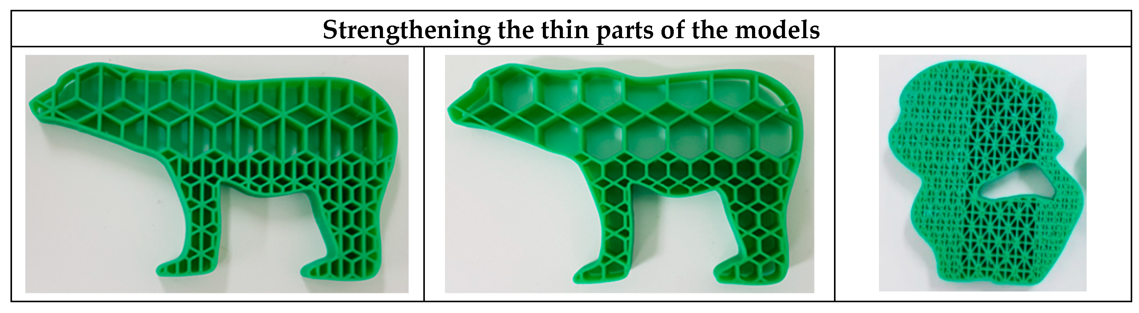
6.3. Strengthening Thin Parts
As a supplementary part of our study, we considered strengthening thin parts of objects as different engineering applications require improved strength of thin parts in samples or industrial models. In fact, thins parts of objects less stress-sustainable, therefore we determined the thin parts of models via visual observation and strengthened them by applying a feasible value of , as shown in Figure 9.
7. Conclusions
The main novelty of this study was to demonstrate the successful application of our method for creating a lightweight interior for 3D fabrications and strengthening inner parts of 3D fabrications. In this study, we introduced the pattern element scaling parameter that impacts the physical properties of 3D fabrications, as well as their weight, material consumption, and printing time. By manipulating , it is possible to control the physical properties of 3D fabrications, including weights. Our method can be considered a goal-oriented fabrication approach that can satisfy the desired application demands for 3D fabrications. The experimental test provides the evidential proof of the efficiency of our method, the results of which can be seen in Table 1. Moreover, we include subdivision schemes for each proposed pattern. We have shown practical applications of our method in 2D and 3D models, for the conducted tests we experimented with different models. A key advantage of our method is the controllability of 3D fabrication properties by introducing the parameter .
Author Contributions
Conceptualization, S.-M.C.; Funding acquisition, S.-M.C.; Investigation, K.C.; Methodology, K.C.; Project administration, S.-M.C.; Software, K.C.; Supervision, S.-M.C.; Validation, S.-M.C.; Visualization, K.C.; Writing—original draft, K.C.; Writing—review & editing, K.C. and S.-M.C.
Funding
This research was funded by Ministry of Science and ICT, Korea: IITP-2019-2016-0-00312.
Conflicts of Interest
The authors declare no conflict of interest.
References
- Osswald, T.A.; Puentes, J.; Kattinger, J. Fused filament fabrication melting model. Add. Manuf. 2018, 22, 51–59. [Google Scholar] [CrossRef]
- Hull, C.W. Apparatus for production of three-dimensional objects by stereolithography. U.S. Patent 4,575,330, 11 March 1986. [Google Scholar]
- Beaman, J.J.; Deckard, C.R. Selective laser sintering with assisted powder handling. U.S. Patent 4,938,816, 17 October 1986. [Google Scholar]
- Maya. Available online: https://www.autodesk.com/products/maya/overview (accessed on 8 August 2019).
- Rhinoceros. Available online: https://www.rhino3d.com/ (accessed on 8 August 2019).
- 3DS MAX. Available online: https://www.autodesk.com/products/3ds-max/overview (accessed on 8 August 2019).
- Ultimaker Cura. Available online: https://ultimaker.com/en/products/ultimaker-cura-software (accessed on 8 August 2019).
- KISSlicer. Available online: http://www.kisslicer.com/ (accessed on 8 August 2019).
- Slic3r. Available online: https://slic3r.org/ (accessed on 8 August 2019).
- Wu, J. Continuous Optimization of. Adaptive Quadtree Structures. Comput. Aided Des. 2018, 102, 72–82. [Google Scholar] [CrossRef]
- Wang, W.; Wang, T.Y.; Yang, Z.; Liu, L.; Tong, X.; Tong, W.; Deng, J.; Chen, F.L.; Liu, X. Cost-effective printing of 3D objects with skin-frame structures. ACM Trans. Graphics 2013, 32, 177. [Google Scholar] [CrossRef]
- Lu, L.; Sharf, A.; Zhao, H.; Wei, Y.; Fan, Q.; Chen, X.; Savoye, Y.; Tu, C.; Cohen-Or, D.; Chen, B. Build-to-last: Strength to weight 3D printed objects. ACM Trans. Graphics 2014, 33, 97. [Google Scholar] [CrossRef]
- Wu, J.; Aage, N.; Westermann, R.; Sigmund, O. Infill optimization for additive manufacturing–approaching bone-like porous structures. IEEE Trans. Visual Comput. Graphics 2017, 24, 1127–1140. [Google Scholar] [CrossRef] [PubMed]
- Ying, J.; Lu, L.; Tian, L.; Yan, X.; Chen, B. Anisotropic Porous Structure Modeling for 3D Printed Objects. Comput. Graphics 2018, 70, 157–164. [Google Scholar] [CrossRef]
- Li, D.; Dai, N.; Jiang, X.; Shen, Z.; Chen, X. Density Aware Internal Supporting Structure Modeling of 3D Printed Objects. In Proceedings of the International Conference on Virtual Reality and Visualization (ICVRV), Xiamen, China, 17–18 October 2015; pp. 209–215. [Google Scholar]
- Zhang, X.; Xia, Y.; Wang, J.; Yang, Z.; Tu, C.; Wang, W. Medial axis tree-an internal supporting structure for 3D printing. Comput. Aided GeomDesign 2015, 35, 149–162. [Google Scholar] [CrossRef]
- Schumacher, C.; Bickel, B.; Rys, J.; Marschner, S.; Daraio, C.; Gross, M. Microstructures to control elasticity in 3d printing. ACM Trans. Graphics 2015, 34, 136. [Google Scholar] [CrossRef]
- Martínez, J.; Dumas, J.; Lefebvre, S. Procedural voronoi foams for additive manufacturing. ACM Trans. Graphics 2016, 35, 44. [Google Scholar] [CrossRef]
- Wu, J.; Wang, C.C.; Zhang, X.; Westermann, R. Self-supporting rhombic infill structures for additive manufacturing. Comput.-Aided Des. 2016, 80, 32–42. [Google Scholar] [CrossRef]
- Lee, M.; Fang, Q.; Cho, Y.; Ryu, J.; Liu, L.; Kim, D.S. Support-free hollowing for 3D printing via Voronoi diagram of ellipses. Comput.-Aided Des. 2018, 101, 23–36. [Google Scholar] [CrossRef]
- Deaton, J.D.; Grandhi, R.V. A survey of structural and multidisciplinary continuum topology optimization: Post 2000. Struct. Multi. Optimum 2014, 49, 1–38. [Google Scholar] [CrossRef]
- Wu, J.; Dick, C.; Westermann, R. A system for high resolution topology optimization. IEEE Trans. Visual Comput. Graphics 2016, 22, 1195–1208. [Google Scholar] [CrossRef] [PubMed]
- Du Plessis, A.; Broeckhoven, C.; Yadroitsava, I.; Yadroitsev, I.; Hands, C.H.; Kunju, R.; Bhate, D. Beautiful and Functional: A Review of Biomimetic Design in Additive Manufacturing. Add. Manuf. 2019, 27, 408–427. [Google Scholar] [CrossRef]
- Dogan, K.M.; Suzuki, H.; Gunpinar, E.; Kim, M.S. A generative sampling system for profile designs with shape constraints and user evaluation. Comput.-Aided Des. 2019, 111, 93–112. [Google Scholar] [CrossRef]
- Ma, W. Subdivision surfaces for CAD- an overview. Comput.-Aided Des. 2005, 37, 693–709. [Google Scholar] [CrossRef]
- Schaefer, S.; Goldman, R. Non-uniform subdivision for B-splines of arbitrary degree. Comput. Aided Geom. Des. 2009, 26, 75–81. [Google Scholar] [CrossRef]
- Fang, M.E.; Jeong, B.; Yoon, J. A family of non-uniform subdivision schemes with variable parameters for curve design. Appl. Math. Comput. 2017, 313, 1–11. [Google Scholar] [CrossRef]
- Catmull, E.; Clark, J. Recursively Generated B-Spline Surfaces on Arbitrary Topological Meshes. Comput.-Aided Des. 1978, 10, 350–355. [Google Scholar] [CrossRef]
- Loop, C.T. Smooth Subdivision Surfaces Based on Triangles. M.S. thesis, University of Utah, Salt Lake City, UT, USA, 1987. [Google Scholar]
- Zorin, D.; Schröder, P. A unified framework for primal/dual quadrilateral subdivision schemes. Comput. Aided Geom. Des. 2011, 18, 429–454. [Google Scholar] [CrossRef]
- Ali, M.; Qamhiyah, A.; Flugrad, D.; Shakoor, M. Theoretical and finite element study of a compact energy absorber. Adv. Eng. Software 2008, 39, 95–106. [Google Scholar] [CrossRef]
Figure 1.
Construction with scaled elements.
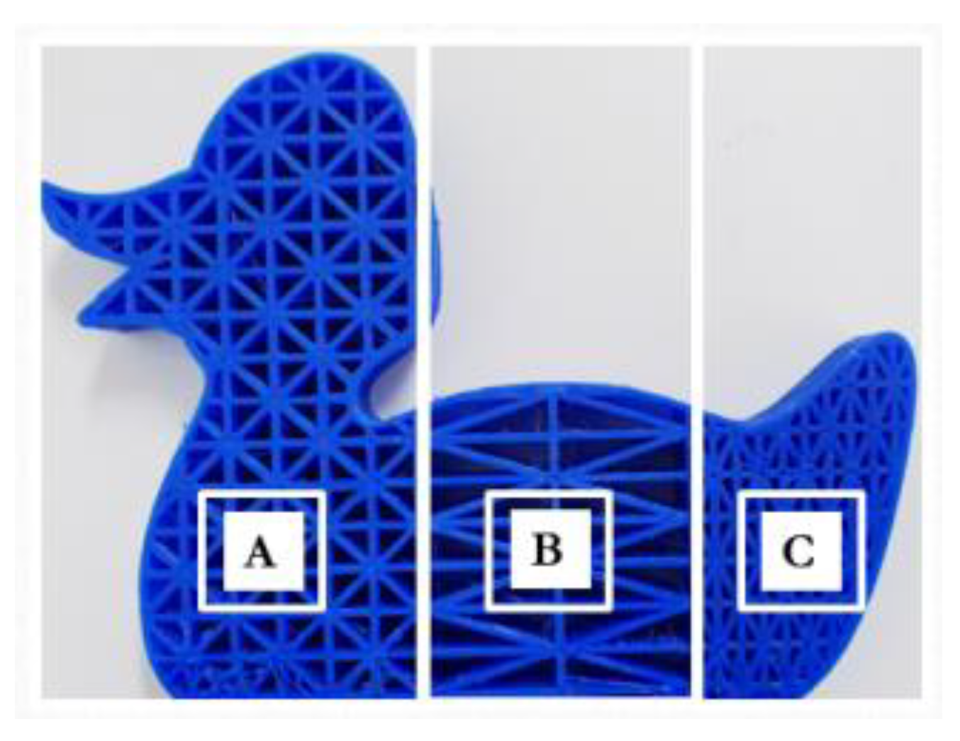
Figure 2.
Combined Patterns.
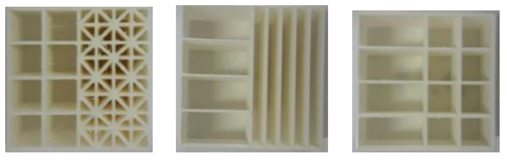
Figure 3.
Topological subdivision rule for the star grid (SG) pattern.
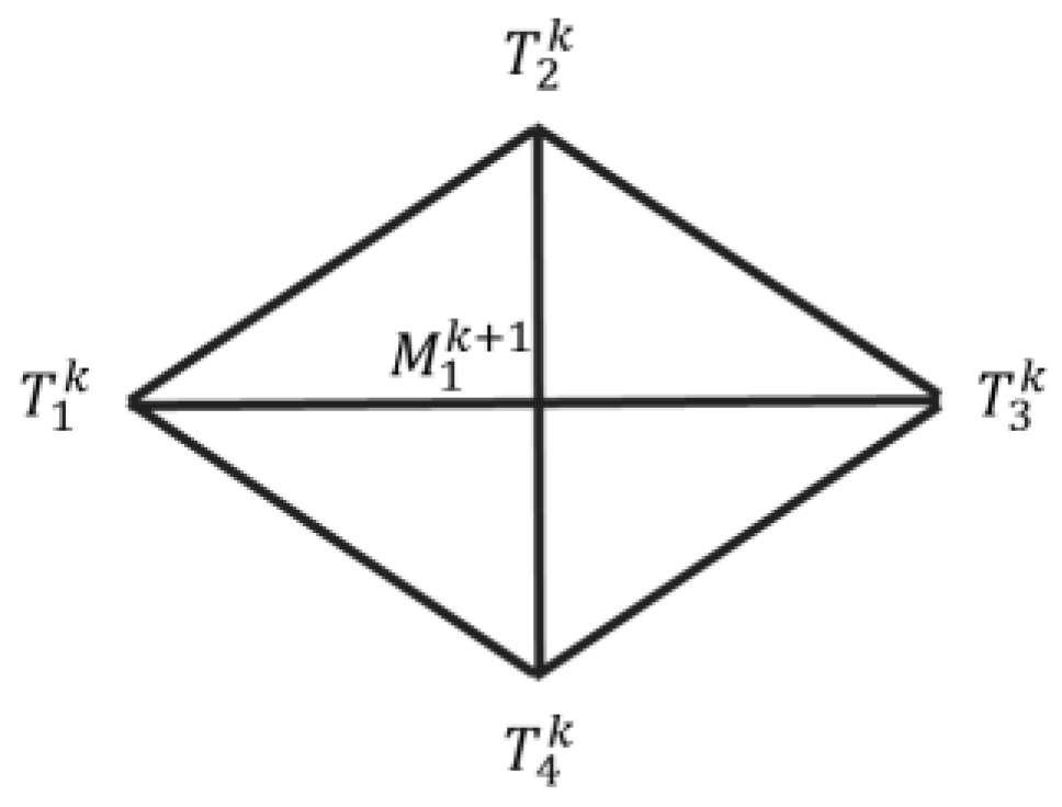
Figure 4.
The output of the SG pattern.
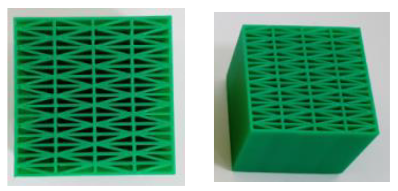
Figure 5.
The outputs with (left) and (right).
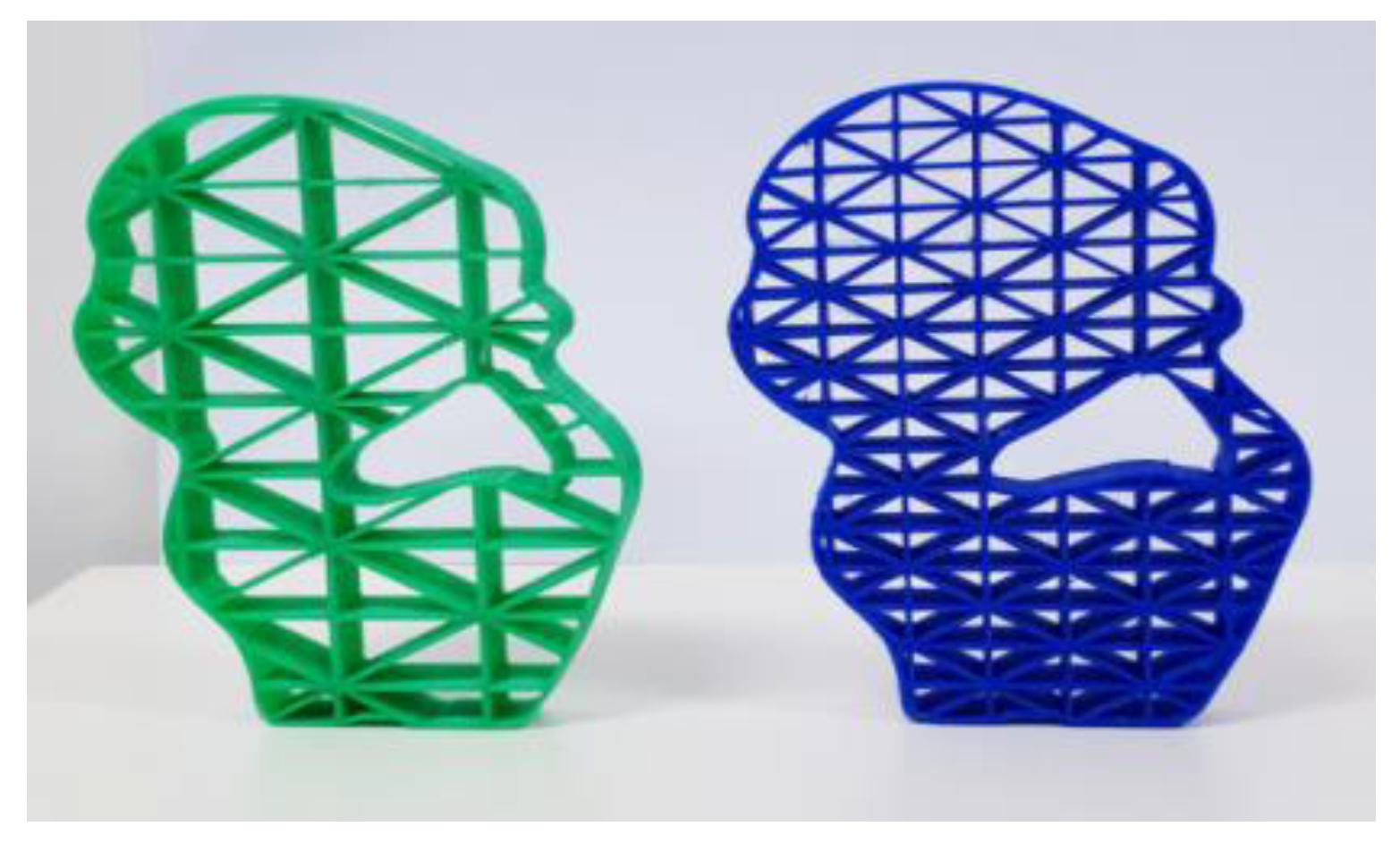
Figure 6.
Topological rules for two types of hexagonal patterns: (left) Hexagonal pattern and (right) hexagonal trapezoid pattern.
Figure 6.
Topological rules for two types of hexagonal patterns: (left) Hexagonal pattern and (right) hexagonal trapezoid pattern.
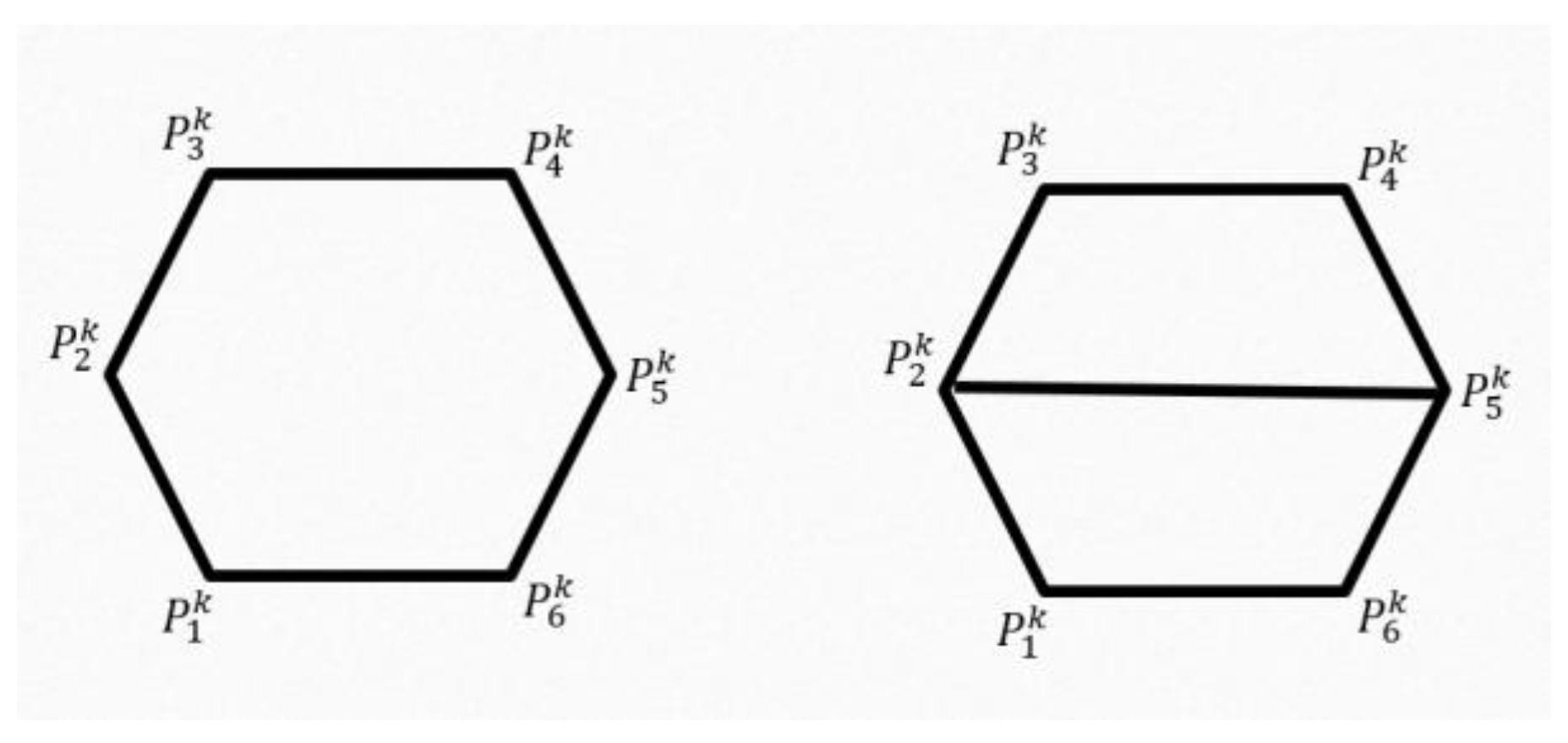
Figure 7.
The outputs for two hexagonal patterns: (right) hexagonal pattern and (left) hexagonal trapezoid.
Figure 7.
The outputs for two hexagonal patterns: (right) hexagonal pattern and (left) hexagonal trapezoid.
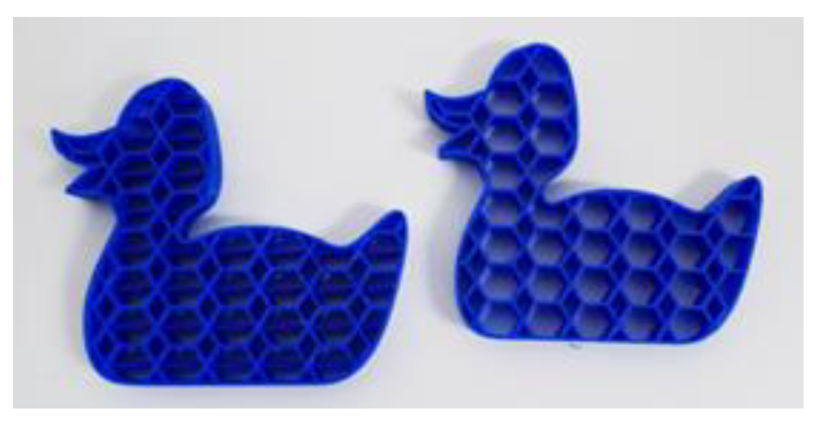
Figure 8.
The output of multilevel design for hexagonal trapezoid pattern.
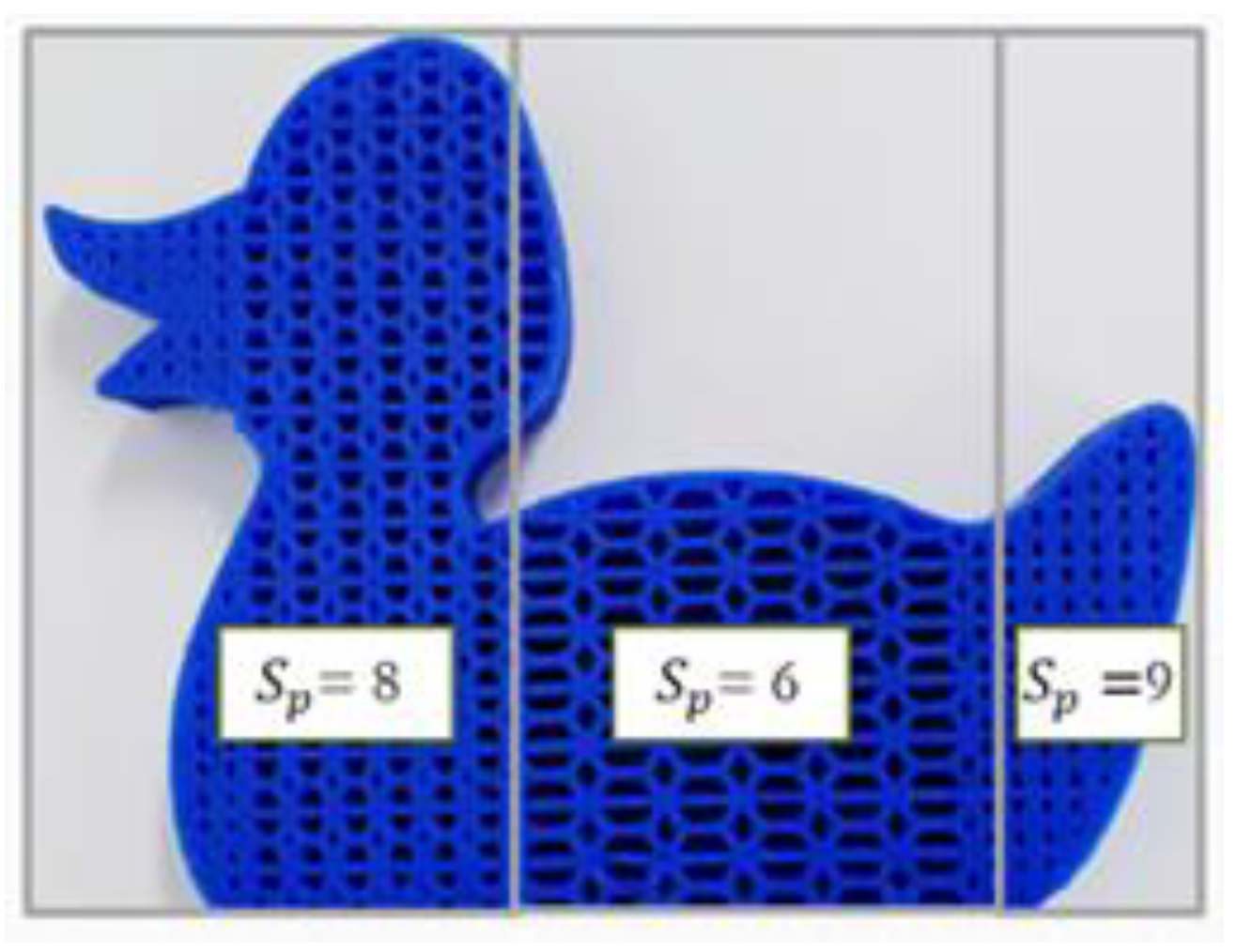
Figure 9.
Strengthening the thin parts of the models.

Table 1.
Weights of models used for multilevel design.
| No. | Model | Weights of Models with Interiors Having a Multilevel Design (Thickness for All Models is 0.8 mm) | ||
|---|---|---|---|---|
| Star Grid | Hexagonal | Hexagonal Trapezoid | ||
| 1 | 5 cm × 5 cm × 5 cm Cube |  87 g |  56 g |  74 g |
| 2 | 2D Bear | 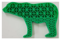 28 g | 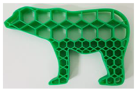 18 g | 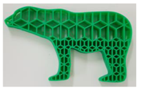 22 g |
| 3 | Bunny Half |  91 g | 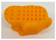 55 g | 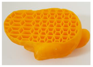 67 g |
| 4 | Bunny | 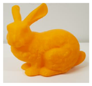 112 g | 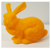 80 g |  95 g |
Table 2.
Comparison table for SG and hexagonal trapezoid.
| No. | Model | Star Grid vs. Hexagonal Trapezoid | ||
|---|---|---|---|---|
| Star Grid | Hexagonal Trapezoid | |||
| 1 | 2D Duck Length—10 cm Width—4 cm Height—1.2 cm | 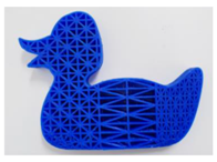 26 g | 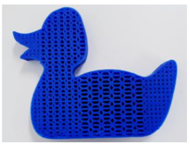 33 g | 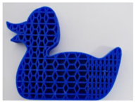 23 g |
Table 3.
Comparison of uniform structures.
| No. | Model | Weight of Models with Uniform Structures | ||
|---|---|---|---|---|
| Star Grid | Hexagonal Pattern | Hexagonal Trapezoid | ||
| 1 | 2D Kitten | 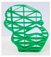 17 g | 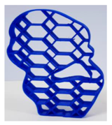 12 g | 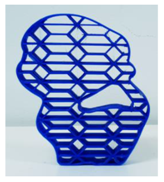 16 g |
| 2 | 3D Cube | 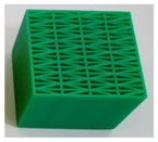 86 g | 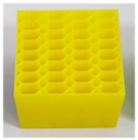 40 g | 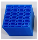 54 g |
Table 4.
Table presenting stress-sustainability results.
| No. | Model | Stress-Sustainability of Models with Uniform Structures | ||
|---|---|---|---|---|
| Star Grid | Hexagonal | Hexagonal Trapezoid | ||
| 1 | Cube | 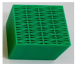 | 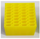 | 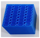 |
| 19600 N | 9140 N | 10900 N | ||
| 2 | Cube | 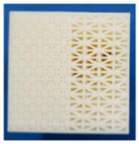 | 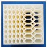 | 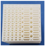 |
| 48400 N | 20300 N | 29500 N | ||
© 2019 by the authors. Licensee MDPI, Basel, Switzerland. This article is an open access article distributed under the terms and conditions of the Creative Commons Attribution (CC BY) license (http://creativecommons.org/licenses/by/4.0/).
Share and Cite
MDPI and ACS Style
Chynybekova, K.; Choi, S.-M. Multilevel Design for the Interior of 3D Fabrications. Symmetry 2019, 11, 1029. https://doi.org/10.3390/sym11081029
AMA Style
Chynybekova K, Choi S-M. Multilevel Design for the Interior of 3D Fabrications. Symmetry. 2019; 11(8):1029. https://doi.org/10.3390/sym11081029
Chicago/Turabian StyleChynybekova, Kanygul, and Soo-Mi Choi. 2019. "Multilevel Design for the Interior of 3D Fabrications" Symmetry 11, no. 8: 1029. https://doi.org/10.3390/sym11081029
Note that from the first issue of 2016, this journal uses article numbers instead of page numbers. See further details here.