Article

Damage Characteristics Analysis of the Truncated Cone-Shaped PELE Projectile

College of Liberal Arts and Sciences, National University of Defense Technology, Changsha 410073, China
*
Authors to whom correspondence should be addressed.
Symmetry 2019, 11(8), 1025; https://doi.org/10.3390/sym11081025
Submission received: 17 July 2019 / Revised: 5 August 2019 / Accepted: 6 August 2019 / Published: 9 August 2019

Abstract

:
The PELE (penetrator with enhanced lateral efficiency) projectile is a new type of penetrator, which has both penetration and fragmentation effects. The damage characteristics of the PELE projectile have never been studied from the perspective of changing the shape of the projectile structure until now. This paper hopes to improve the damage power by changing the structural shape of PELE projectile, and the concept of a truncated cone-shaped PELE projectile is first put forward. In order to compare and analyze the damage power of the truncated cone-shaped PELE projectile and the conventional PELE projectile, six sets of simulation conditions were designed, and the penetration ability and fragmentation effect were used as the main evaluation indicators. According to the known structural parameters of the PELE projectile, the range of angle α of the truncated cone-shaped PELE projectile was determined to be 86.2°–90°. In addition, there is little difference in penetration ability between the two different types of PELE projectile; the damage effect of the truncated cone-shaped PELE projectile on the after-effect target is better than that of the conventional PELE projectile. It is hoped that through further structural optimization, the truncated cone-shaped PELE projectile will have more extensive engineering application value.

Graphical Abstract

1. Introduction

The PELE (penetrator with enhanced lateral efficiency) projectile [1,2] is a kind of armor-piercing projectile, which is the result of a cooperation between the French-German Research Institute Saint Louis (ISL), the GEKE Technology in Freiburg and the Diehl Munitionssysteme [1,2,3,4,5]. Compared with the conventional armor-piercing projectiles, the PELE projectile can better meet the needs of modern battlefields, especially in the aspect of after-effect damage to targets. The PELE projectile is mainly composed of a high-density outer casing and a low-density inner core, without any pyrotechnical agents and fuses. When the PELE projectile penetrates the target, the low-density inner core is compressed to generate radial expansion, and the internal pressure of the projectile rises rapidly. After the projectile perforates the target, the internal and external pressure difference causes the outer casing to break and form fragments. Therefore, it can be seen that the PELE projectile not only retains the penetration ability of conventional armor-piercing projectiles, but also has a certain fragmentation effect, which effectively solves the problem of insufficient after-effect damage.
As for the damage characteristics of PELE projectiles, many scholars mainly focused on the following factors: Outer casing material, inner core material, inner core combination type, length-diameter ratio of projectile, impact velocity, intersection attitude, thickness of projectile rear, target plate thickness and so on. Paulus [2] studied the effect of inner core material on the damage characteristics, and the test results show that with the increase of the density of inner core material, the length of the lateral effect of projectile body becomes shorter. Ding [6] studied the damage characteristics of the PELE projectile with gradient density inner core material, the results indicate that the negative gradient inner core combination is superior to the other combinations in terms of the penetration ability and fragmentation effect. Du [7] and Zhu [8] studied the effects of the ratio of the inside to outside diameter, the length-diameter ratio and impact velocity on the lateral enhancement of PELE projectile. The results show that when the ratio of inside to outside diameter is 0.5–0.7 and the length-diameter ratio is 3–5, the PELE projectile can easily penetrate the target plate. Tu [9] studied the influence of target plate thickness on the penetration after-effect of PELE projectile, the results show that the number of fragments is quadratic with the target plate thickness, and the scattering angle of fragments is linearly decreasing with the target plate thickness. In order to understand the penetration process and mechanism of PELE projectile more intuitively, Paulus [5], Fan [10] and Verreault [11,12,13] carried out a lot of numerical simulations on the penetration process of the PELE projectile, and the key factors which affect the damage power of PELE projectile were obtained.
Based on the previous researches on the PELE projectile, it can be found that the damage characteristics of the PELE projectile have never been studied from the perspective of changing the structural shape of the projectile. The structural design of the conventional PELE projectile is usually cylindrical in shape, and it is mainly concerned with two technical indicators: Penetration ability and fragmentation effect. Since PELE projectiles are mainly aimed at thin targets, the penetrating ability of PELE projectile is usually guaranteed. In order to increase the damage area to the follow-up targets and improve the damage level, it is necessary to enhance the fragmentation effect of the PELE projectile. Therefore, this paper hopes to improve the effective damage area of fragments by changing the structural shape of PELE projectile, and a new type of truncated cone-shaped PELE projectile structure will be designed. The penetration ability and fragmentation effect of the truncated cone-shaped PELE projectile will be compared comprehensively by designing a number of simulation conditions, to obtain the damage characteristics of the truncated cone-shaped PELE projectile.

2. Structural Design of the Truncated Cone-Shaped PELE Projectile

2.1. Design Idea of the Truncated Cone-Shaped PELE Projectile

When the conventional PELE projectile impacts the target, the inner core will be compressed due to the impedance of the target. Considering the compressibility of the inner core and the circumferential binding of the outer casing to the inner core, the inner core will generate radial pressure on the outer casing according to the Poisson effect. Then, the shear failure occurs in the outer casing under the action of radial pressure of the inner core, so that the outer casing breaks along the axis. Since the force acting on the outer casing along the axis is not uniform, the fragments formed by the fracture of outer casing will deflect under the action of bending moment. Taking the initial velocity direction of the projectile as the positive direction, since the conventional PELE projectile is cylindrical and its busbar of outer casing is parallel to the positive direction, the initial deflection angle of fragments can be regarded as 0°. It is assumed that the initial dispersal velocity of fragments is the same, the larger the deflection angle of the fragments, the larger the effective damage area of the fragments. From this point of view, this paper hopes to change the structural shape of the PELE projectile to make the initial deflection angle of the fragments is greater than 0°, which can improve the deflection angle of the fragments during the actual scattering process to some extent.
Therefore, a new type of truncated cone-shaped PELE projectile structure was designed. The specific design idea of the truncated cone-shaped PELE projectile is as follows: The structure shape of the PELE projectile is changed from cylindrical to truncated cone-shaped (the diameter of projectile’s head is larger than that of projectile’s rear), and the initial angle between the busbar and the axial direction of the truncated cone-shaped PELE projectile is obviously larger than 0°. In this case, the initial deflection angle of fragments corresponding to the projectile structure is larger than 0°, which is conducive to improving the effective damage area of fragments.
During the structural design of truncated cone-shaped PELE projectile, in order to facilitate the comparative analysis with the conventional PELE projectile, the design principle should ensure that the four indexes of the impact end (projectile head), the length-diameter ratio of projectile, the thickness of outer casing and the sealing thickness of projectile rear are the same. The simplified diagrams of the conventional PELE projectile structure and the truncated cone-shaped PELE projectile structure are shown in Figure 1 and Figure 2, respectively.

2.2. Determination of Structural Parameters of the Truncated Cone-Shaped PELE Projectile

According to the research results in literature [8], the length-diameter ratio of PELE projectile is suitable between 4:1 and 6:1. Therefore, the length-diameter ratio of PELE projectile is determined to be 5:1 in this paper, the total length of projectile is L = 50 mm, the outer diameter of outer casing is D = 10 mm, the diameter of inner core is d = 6 mm, the wall thickness of outer casing is δ = 2 mm, and the sealing thickness of projectile rear is h = 5 mm.
The truncated cone-shaped PELE projectile still has symmetrical structure, so the symmetrical simplification can be performed in the geometry analysis of this section and the establishment of finite element model below. According to the geometric principle, the conventional PELE projectile has the following geometric relations:
V casing = π 4 D 2 h + π 4 ( D 2 d 2 ) ( L h )
V inner = π 4 d 2 ( L h )
δ = 1 2 ( D d )
Similarly, the geometric relationship of the truncated cone-shaped PELE projectile can also be obtained. For ease of analysis, two intermediate quantities are defined:
The cone height H0 corresponding to d0 is:
H 0 = d 0 2 tan α
The cone height H1 corresponding to d1 is:
H 1 = d 1 2 tan α
Therefore, the truncated cone-shaped PELE projectile has the following geometric relations:
V inner = 1 3 π ( d 0 2 ) 2 H 0 1 3 π ( d 1 2 ) 2 H 1 = 1 24 π tan α ( d 0 3 d 1 3 )
V casing = 1 24 π tan α ( D 3 D 0 3 ) V i n n e r = 1 24 π tan α [ ( D 3 D 0 3 ) ( d 0 3 d 1 3 ) ]
δ = 1 2 ( D d 0 ) sin α
The range of angle α can be obtained under the condition that the wall thickness of the outer casing and the sealing thickness of projectile rear are unchanged. The geometric structure of the truncated cone-shaped PELE projectile corresponding to the different angle α is shown in Figure 3. The radius of outer casing is OD = 5 mm, the wall thickness of outer casing is CD = 2 mm, the length of projectile is OA = 50 mm, and the sealing thickness of projectile rear is AB = 5 mm.
By analyzing the structure of the truncated cone-shaped projectile, it can be seen that when the rectangular OCFB degenerates into a triangular OCB (that is, the point F coincides with point B), the angle α reaches the minimum value. Thus, the minimum value of angle α can be obtained as:
tan α = O B O C = 45 3 = 15 α = 86.2 °
Therefore, it can be determined that the value of angle α of the truncated cone-shaped PELE projectile designed in this paper ranges from 86.2°–90°.
Taking the projectile structure with α = 88° in Figure 3b as an example, the specific values of each parameter can be quickly determined according to the geometric relationship, as shown in Table 1. The meanings of the parameters in Table 1 are consistent with those in Figure 2.
According to the known dimensions in Table 1, the specific parameters of the volume and mass of the outer casing and inner core of the conventional PELE projectile can be obtained as follows:
V casing = π 4 D 2 h + π 4 ( D 2 d 2 ) ( L h ) = π 4 [ D 2 h + ( D 2 d 2 ) ( L h ) ] = π 4 [ 1 × 0.5 + ( 1 2 0.6 2 ) × 4.5 ] = 2.655 cm 3
V inner = π 4 d 2 ( L h ) = π 4 × ( 0.6 2 × 4.5 ) = 1.272 cm 3
M = M casing + M inner = 18.1 × 2.655 + 2.65 × 1.272 51.4 g
Similarly, the specific parameters of the volume and mass of the outer casing and inner core of the truncated cone-shaped PELE projectile with α = 88° can also be obtained as follows:
V inner = 1 3 π ( d 0 2 ) 2 H 0 1 3 π ( d 1 2 ) 2 H 1 = 1 24 π tan α ( d 0 3 d 1 3 ) = 1 24 π × tan 88 × ( 0.6 3 0.2857 3 ) = 0.722 cm 3
V casing = 1 24 π tan α ( D 3 D 0 3 ) V inner = 1 24 π tan α [ ( D 3 D 0 3 ) ( d 0 3 d 1 3 ) ] = 1 24 π × tan 88 × [ ( 1 0.6508 3 ) ( 0.6 3 0.2857 3 ) ] = 1.993 cm 3
M = M casing + M inner = 18.1 × 1.993 + 2.65 × 0.7223 38.0 g
From the above formulas, it can be clearly seen that the mass of the truncated cone-shaped PELE projectile with α = 88° is 26.1% less than that of the conventional PELE projectile. The reduction of missile mass can improve the payload carried by the weapon launching platform, and it can improve the initial launching speed of missile. It is assumed that the initial propellant mass of PELE projectile remains unchanged, that is, the initial kinetic energy of projectile generated by the propellant remains unchanged. According to the kinetic energy formula E = m v 2 / 2 , the initial velocities of the truncated cone-shaped PELE projectile under different conditions can be calculated, as shown in Table 2.

3. Numerical Simulation

In this paper, the damage characteristics of the truncated cone-shaped PELE projectiles will be studied mainly by using the non-linear dynamics software AUTODYN [14]. AUTODYN (Century Dynamics, Fort Worth, TX, USA) is an interactive, non-linear, explicit dynamics analysis software for solving highly nonlinear dynamic problems of solids, fluids, gases and their interactions. The software includes its own material library, and it has unique stochastic failure modes, which can reflect the randomness and non-uniformity exhibited by the material. Our team has done a lot of work in the early stages and obtained a set of algorithms (crack softening algorithm and stochastic failure algorithm) which can simulate the penetration process of PELE projectile very well. The related academic achievements have been published, which can be seen in the literature [6,15].

3.1. Finite Element Model

The truncated cone-shaped PELE projectile with α = 88° is taken as an example for numerical simulation. The whole simulation model is divided into four parts: Outer casing, inner core, target plate and after-effect target. The structural parameters of the truncated cone-shaped PELE projectile are listed in Table 1. The length and width of the target plate and the after-effect target are both 120 mm, and the material and thickness of target plate will be selected according to different conditions. The thickness of after-effect target is 1 mm, and the distance between the target plate and after-effect target is 150 mm. The whole modeling process was completed by HyperMesh software (Altair Engineering, Detroit, MI, USA). During the modeling process, the projectile and the target are made of unstructured hexahedral meshes, and the mesh size of projectile is 0.25 mm. In order to improve the computational efficiency, the gradient mesh is used for the target plate and after-effect target, and the mesh densification area (20×20 mm) is twice the diameter of the projectile head. In the 20×20 mm area of the target center, the mesh size of target is 0.25 mm. The number of the gradient meshes from the encrypted area to the boundary is set as 70, and the gradient mesh size is determined by the modeling software. In other words, from the center to the boundary of the target plate, the mesh density becomes lower and lower.
In the process of experiment, PELE projectiles are fired by guns to obtain initial velocity, and then hit the target plate—the target is usually fixed around. In the simulation process, we directly set specific values for the initial velocity of the projectile in the software to equivalent to that of the velocity of the projectile obtained by the explosive driving under the actual conditions. As for the target plate, the fixed boundary and transmissive boundary condition is applied to the edge of target plate. By adding such boundary conditions to the target plate, we can approximate that the finite size target can reflect the characteristics of a semi-infinite target. In addition, it is assumed that the projectile impacts the target in a normal incidence attitude. Since the truncated cone-shaped PELE projectile is still symmetrical, the model can adopt 1/4 simplification under the vertical impact condition. The schematic diagram of the finite element model is shown in Figure 4. In order to clearly show the local contact details between the projectile and target plate, the after-effect target is not shown in Figure 4.

3.2. Material Model and Parameters

In this paper, the selection of the material model and its parameters are referred to in the literature [15]. The principal stress/strain failure model is adopted for the outer casing, and the crack softening algorithm and stochastic failure algorithm are added to the outer casing. The aluminum inner core material adopts the principal stress failure model, and its tensile strength is σT = 0.5 GPa. The plastic strain failure model is adopted for the target material, that is, when the plastic strain reaches a certain level, the material will fail. An artificial erosion algorithm (Erosion) is added to all materials to ensure normal calculations, and the failure erosion algorithm (Failure) is added to the target materials to delete the failed mesh. The geometric strain erosion algorithm (Geometric Strain) is used to the rest of the materials, it can delete the meshes whose instantaneous geometric strain are greater than the given value. In summary, all material parameters are shown in Table 3.

3.3. Simulation Condition

In our previous research on the conventional PELE projectiles, we have done a lot of numerical simulation studies, see the literature [15]. In order to facilitate the comparison of the damage effect of the two different types of PELE projectile, the following principles were set up:
(1)
Keep the initial kinetic energy of the two different types of PELE projectiles consistent.
(2)
The material and thickness of the target plate and the after-effect target are consistent with those of conventional PELE projectile in literature [15].
Therefore, combined with the projectile velocities setting in Table 2 and the target parameters setting in literature [15], the simulation conditions of this paper can be obtained, as shown in Table 4. In addition, it is important to further emphasize that the commended comparisons are valid for the chosen setup. It is known that as far as the features of the target plate modify, different behaviors are obtained. However, in order to obtain the damage law of the truncated cone-shaped PELE projectile, the control variable method is needed, that is, the specific target plate parameters need to be set. The processing method of this paper draws on the impact simulation examples in the literature [15,16].

4. Comparative Analysis of the Numerical Simulation Results

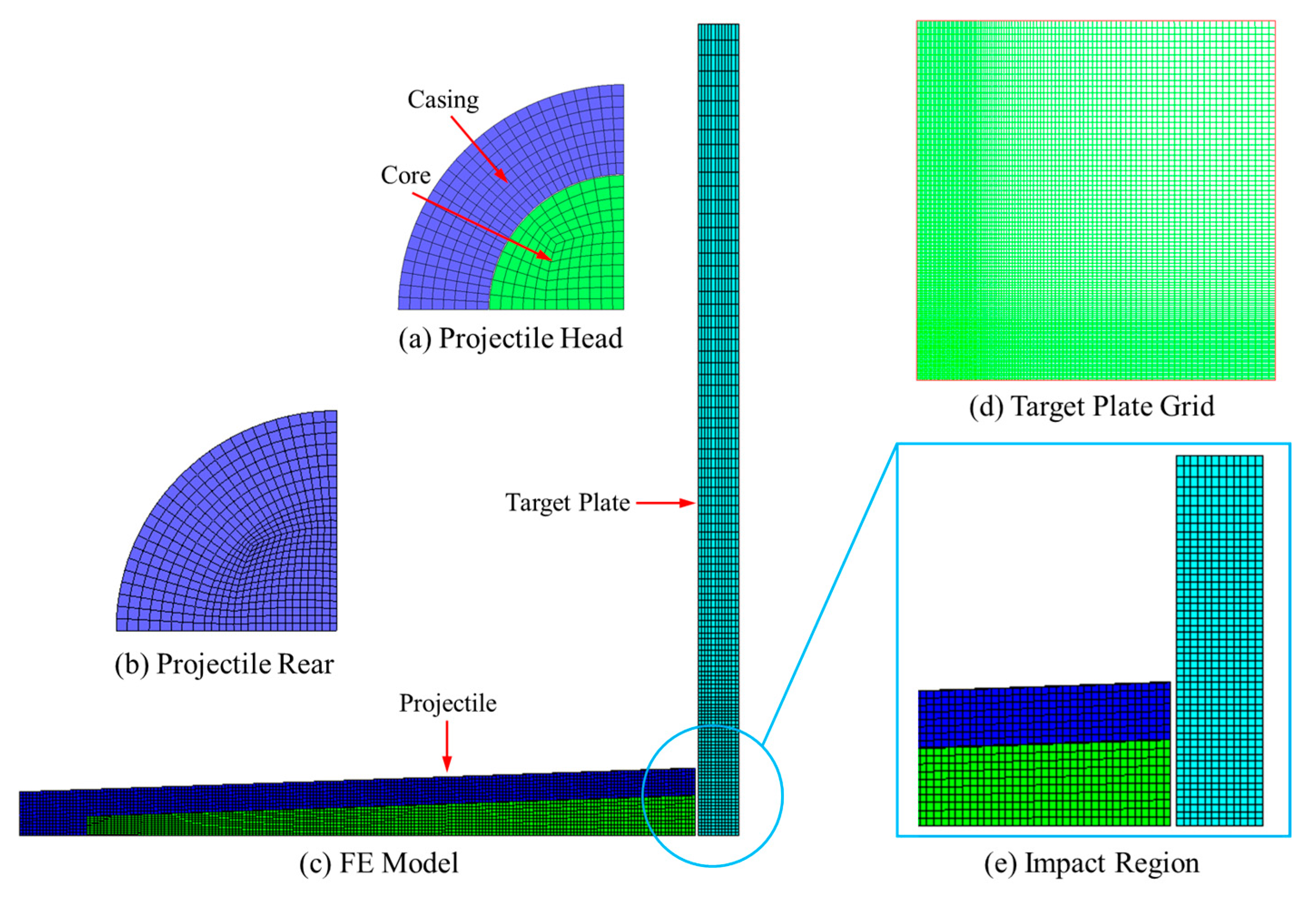
As a special kind of penetrator, the comprehensive damage characteristics of the truncated cone-shaped PELE projectile will be investigated from two aspects: Penetration ability and the fragmentation effect. In the numerical simulation model, two layers of target plate were constructed, namely the target plate and the after-effect target. The target plate is mainly used to reflect the penetration ability of projectile, while the after-effect target is mainly used to reflect the fragmentation effect after the projectile perforating the target plate.

4.1. Comparison of Penetration Ability between the Truncated Cone-Shaped PELE Projectile and Conventional PELE Projectile

When evaluating the penetration ability of projectiles, the axial residual velocity or the loss of axial residual velocity of the projectile is usually selected as an indicator for characterization. However, the precondition is to ensure that the truncated cone-shaped PELE projectile and the conventional PELE projectile have the same initial kinetic energy. From the geometric structure design of the projectile, it can be seen that the mass of the truncated cone-shaped PELE projectile is 26% less than that of the conventional PELE projectile, which results in the different initial velocity of projectile under the same initial kinetic energy. Therefore, it is obviously unreasonable to choose the axial residual velocity or the loss of axial residual velocity as the indicator for characterization. In this section, the residual kinetic energy of the PELE projectile is directly expressed as an indicator, and the kinetic energy change of the PELE projectile after perforating the target plate is mainly analyzed.
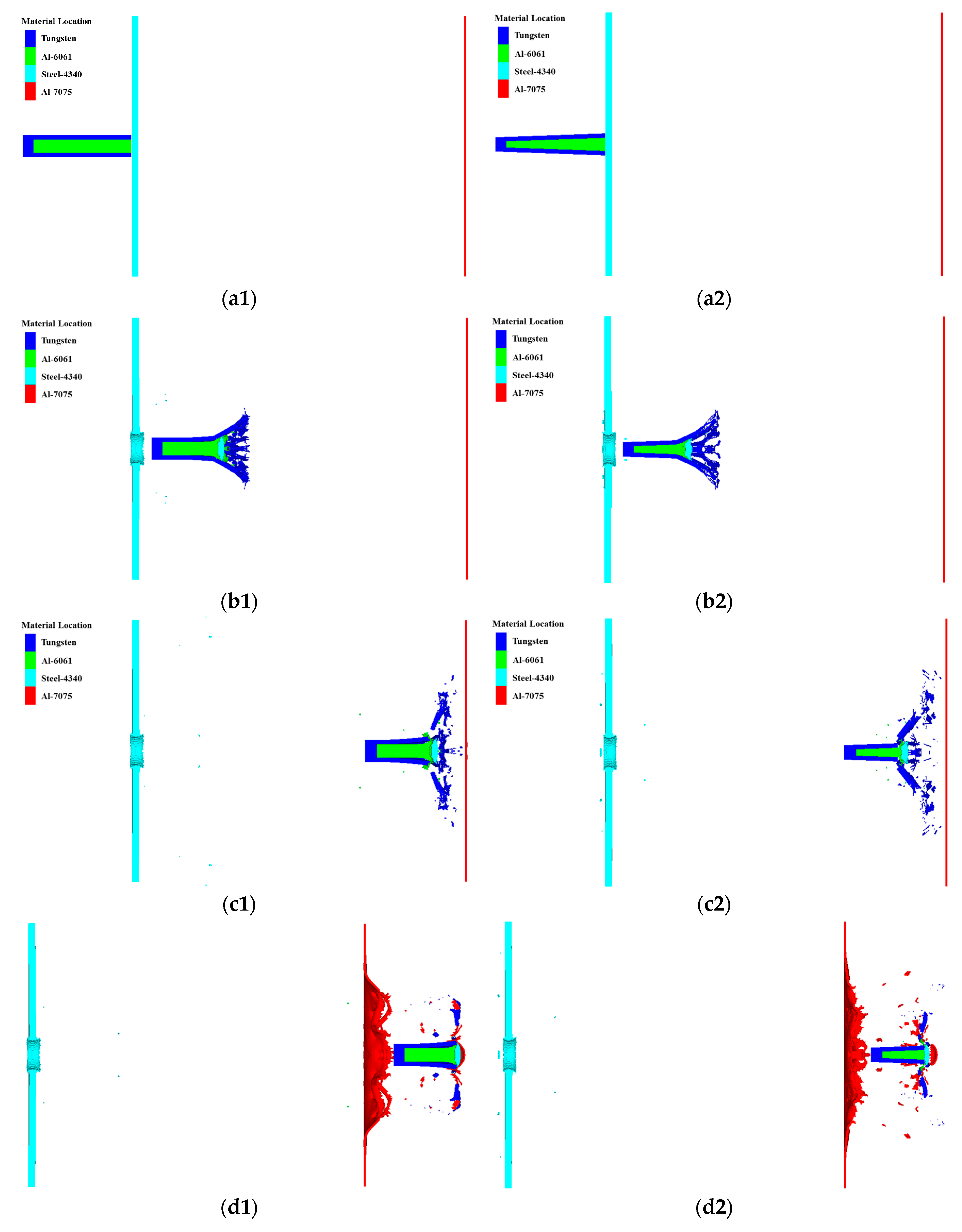
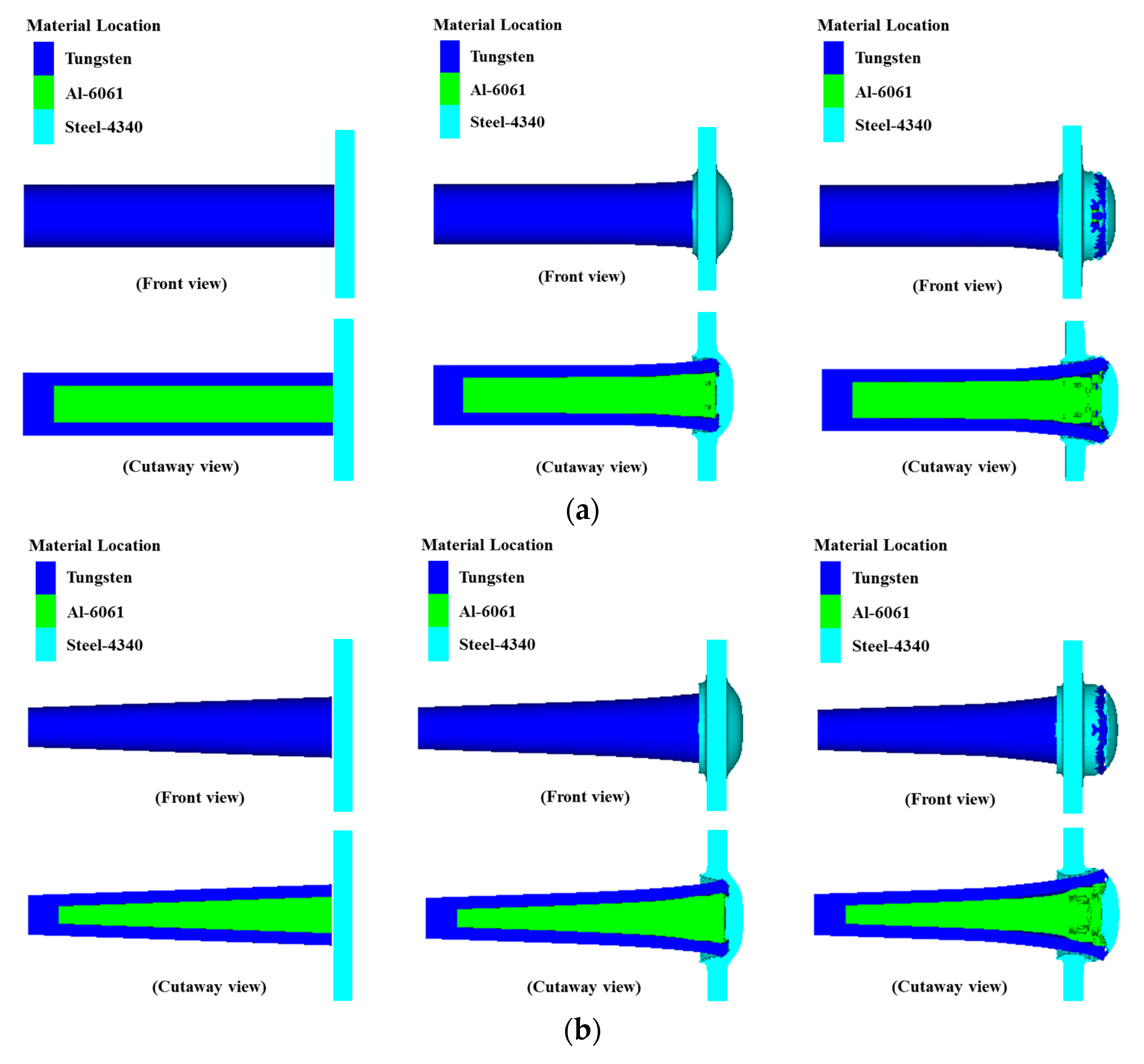
In order to visualize the penetration process of PELE projectiles, this paper takes the #5 working condition as an example and four typical moments were selected, as shown in Figure 5.
The penetrating ability of the projectile can be reflected by the energy loss of the projectile, while the energy loss of the projectile is mainly used for shear energy dissipation of the target plate. Therefore, the energy loss of the projectile in the range from the projectile body and the target plate just touching to the projectile body just perforating the target plate completely is mainly analyzed to characterize the penetration ability of projectile. The local enlargement diagrams of the two different types of PELE projectile penetrating the target plate are shown in Figure 6.
According to the simulation conditions in Table 4, the kinetic energy losses of PELE projectiles after perforating the target plate were counted, as shown in Table 5. The working condition numbers in Table 5 are defined as follows. Taking “#1-1” and “#1-2” as examples, it is explained that “-1” represents the conventional PELE projectile, while “-2” represents the truncated cone-shaped PELE projectile. The projectile velocity and target plate parameters corresponding to the “#1” in Table 5 are consistent with the information corresponding to the “#1” in Table 2 and Table 4.
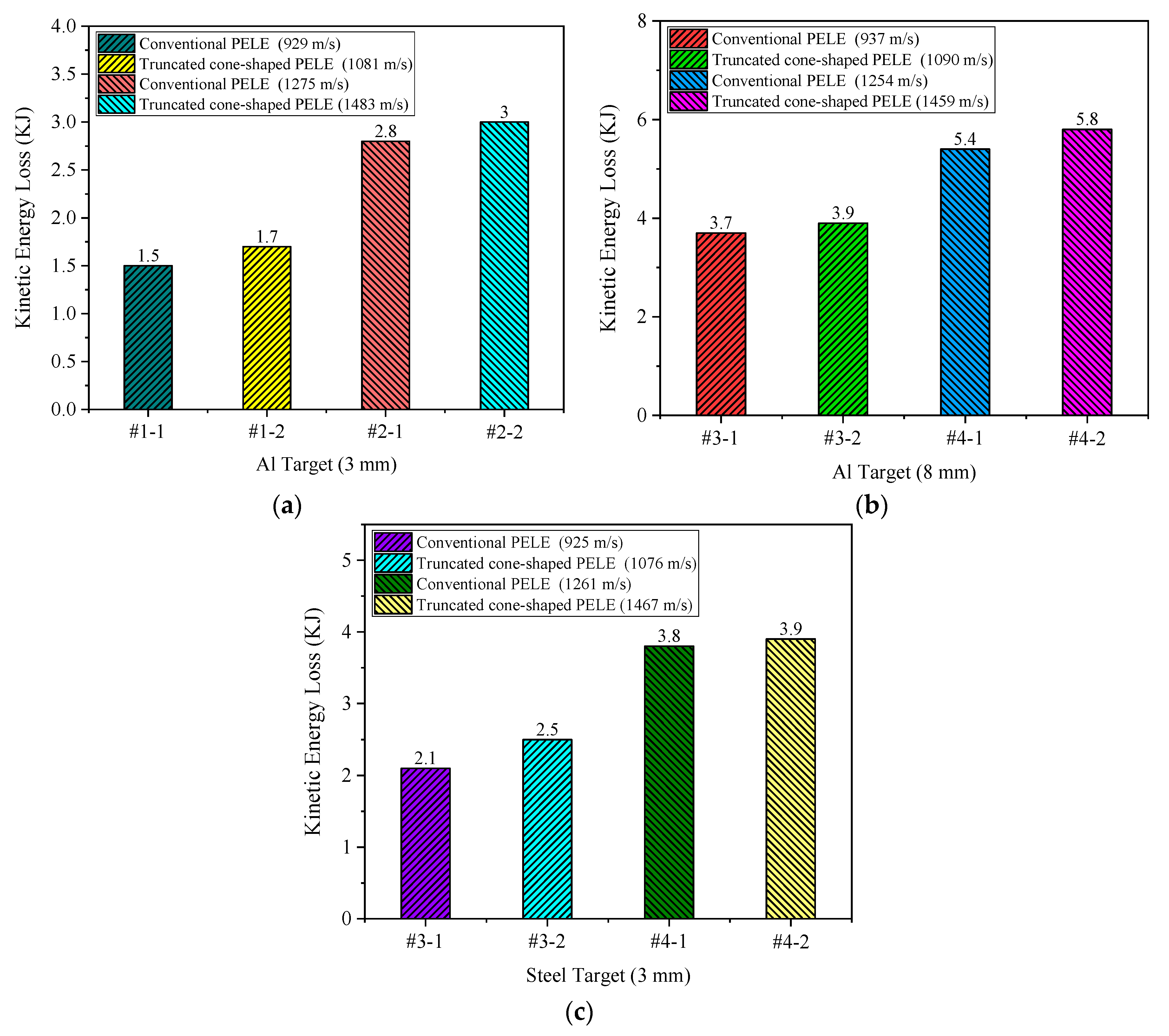
In order to quantify the kinetic energy loss of the conventional PELE projectile and the truncated cone-shaped PELE projectile in the process of penetrating the target plate, the kinetic energy losses corresponding to the different working conditions in Table 5 are expressed in the form of histogram, as shown in Figure 7.
According to the design principle of the truncated cone-shaped projectile, the initial kinetic energy of the two different types of projectiles should be identical in theory. While the mass of the projectile cannot be guaranteed to be completely consistent with the theoretical mass during modeling, it leads to some deviation in the initial kinetic energy of the projectiles in the simulation. From the specific values given in Table 5, the initial kinetic energy difference is small, and it can be basically negligible, so it is approximated that they have the same initial kinetic energy.
Based on the kinetic energy loss after the projectile perforating the target plate shown in Table 5 and Figure 7, it can be seen that the difference of kinetic energy loss between the two different types of PELE projectile is quite small, which indicates that the penetration ability of the two projectiles is quite close. In other words, the penetration ability of the truncated cone-shaped PELE projectile is guaranteed and there is no significant reduction. Although the kinetic energy loss of the two kinds of projectiles is quite close, it can be found that the kinetic energy loss of the truncated cone-shaped PELE projectile is slightly larger than that of the conventional PELE projectile through comparative analysis of all working conditions. The reason for this phenomenon may be related to the resistance of the projectile when it penetrates the target plate.
The resistance of the projectile when it penetrates the target plate mainly consists of four parts. The first part is the resistance caused by the strength of the target material, which is the resistance of the target material to the projectile when it resists its own deformation. The magnitude of this part of the force has nothing to do with the velocity of projectile, but only depends on the strength of the target material. The second part is the inertia force or flow resistance, which is mainly caused by the inertia of the target material itself. The magnitude of the force is proportional to the square of the velocity of projectile. In addition to the above two main resistance terms, the penetration resistance usually includes the viscous effect term and the additional mass term of target material. The relationship between the stress of penetration resistance and penetration velocity is as follows:
σ = c 1 + c 2 v + c 3 v 2 + c 4 v ˙
where c 1 represents the resistance term caused by the strength of target material; c 2 v represents the viscous effect term; c 3 v 2 represents the inertial force term, and c 4 v ˙ represents the additional mass term. Thus, the expression of penetration resistance of projectile can be obtained as follows:
F = σ A = ( c 1 + c 2 v + c 3 v 2 + c 4 v ˙ ) A
where F is the penetration resistance of projectile; A is the cross-sectional area of the impact end of projectile; and c1~c4 are the resistance coefficients. In general, the second term (viscous effect term) and the fourth term (additional mass term) of the resistance expression can be neglected, and the expression of the penetration resistance of projectile can be rewritten as follows:
F = ( c 1 + c 3 v 2 ) A
Based on the above theoretical analysis, when the cross-sectional area of the impact end of the projectile is constant, the greater the impact velocity of the projectile, the greater the penetration resistance experienced by the projectile, and the greater the kinetic energy loss of projectile during the penetration process. Under the same initial kinetic energy condition, the velocity of the truncated cone-shaped PELE projectile is higher than that of the conventional PELE projectile. Therefore, the penetration resistance of the truncated cone-shaped PELE projectile is greater than the conventional PELE projectile, and it means that the kinetic energy loss of the truncated cone-shaped PELE projectile is greater. In addition, it can be seen from Table 5 that when the target plate thickness is unchanged, if the target plate material is changed from Al to steel, the impedance exhibited by the target plate will inevitably increase, so that the kinetic energy loss of projectile during penetration will also inevitably increase. When the target plate material is unchanged, if the target plate thickness changes from 3 mm to 8 mm, the impedance exhibited by the target plate will inevitably increase, so that the kinetic energy loss of projectile during penetration will also inevitably increase.
In summary, there is no significant difference in the penetration ability between the truncated cone-shaped PELE projectile and the conventional PELE projectile. However, due to the impact velocity of the truncated cone-shaped PELE projectile is slightly higher, the penetration resistance of the truncated cone-shaped PELE projectile is slightly greater than that of the conventional PELE projectile, and the greater resistance means there will be a little more kinetic energy loss.

4.2. Comparison of Fragmentation Effect between the Truncated Cone-Shaped PELE Projectile and Conventional PELE Projectile

Compared with the conventional armor-piercing projectile, the PELE projectile has a remarkable advantage in its fragmentation effect after penetrating the target, which can improve the damage level of the target after penetrating to a certain extent. From the conclusions obtained in Section 4.1, it can be seen that there is no obvious difference in penetration ability between the conventional PELE projectile and the truncated cone-shaped PELE projectile. Therefore, this section will focus on the fragmentation effect of the truncated cone-shaped PELE projectile.
In this section, the fragment conversion rate and the damage radius of the after-effect target are mainly investigated to evaluate the fragmentation effect of PELE projectile. The fragment conversion rate of the projectile can be determined by calculating the ratio of the mass of the residual casing to the mass of the initial casing. That is to say, the fragment conversion rate can be converted to the mass change rate of the outer casing. The damage radius of the after-effect target can be measured directly.
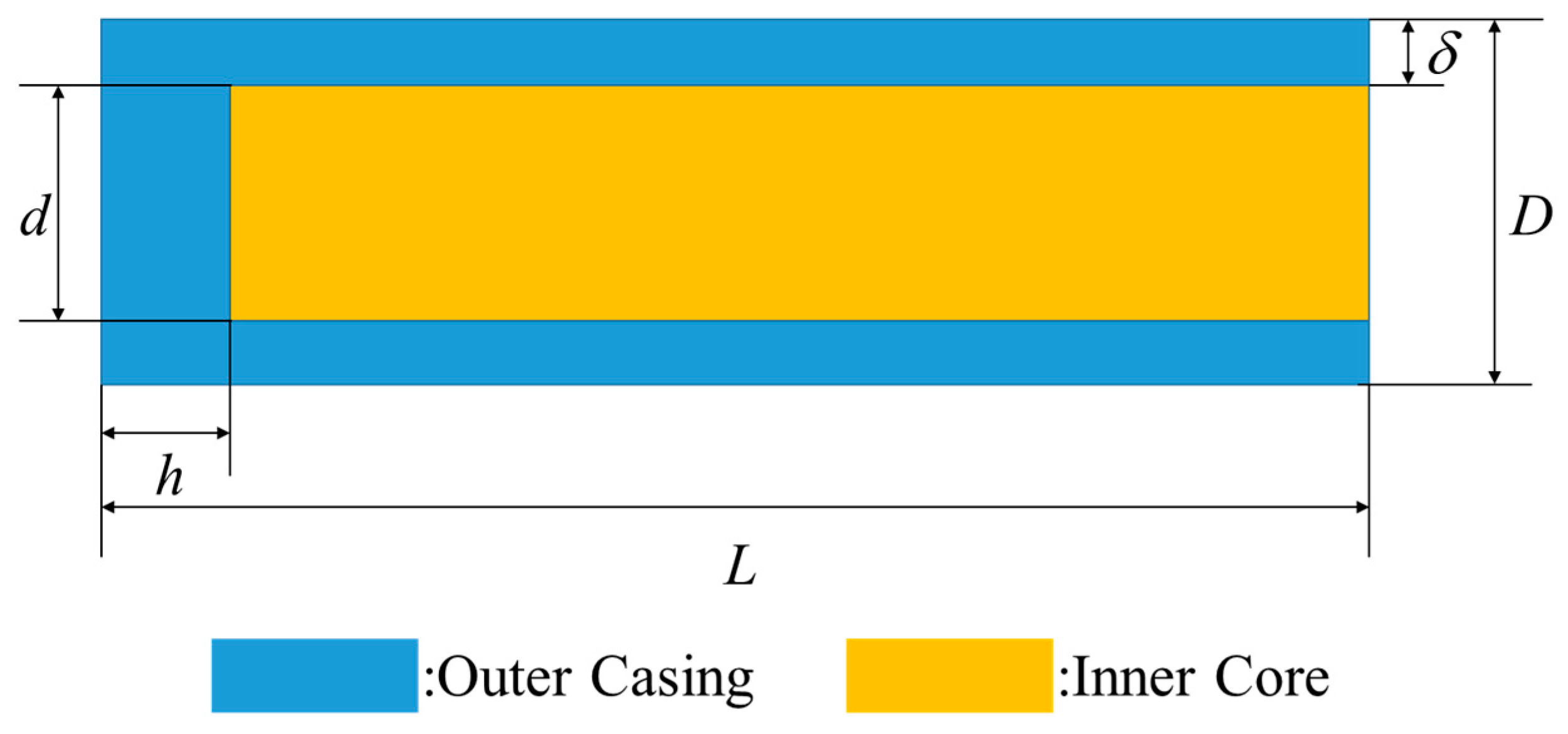
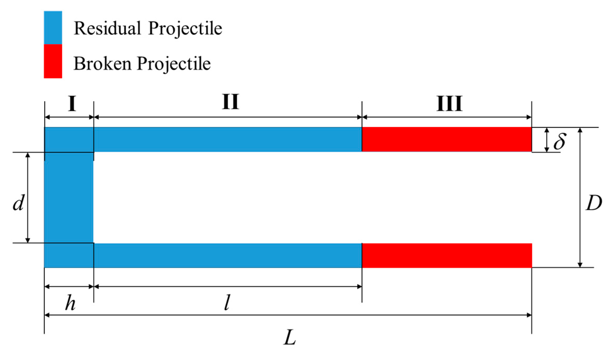
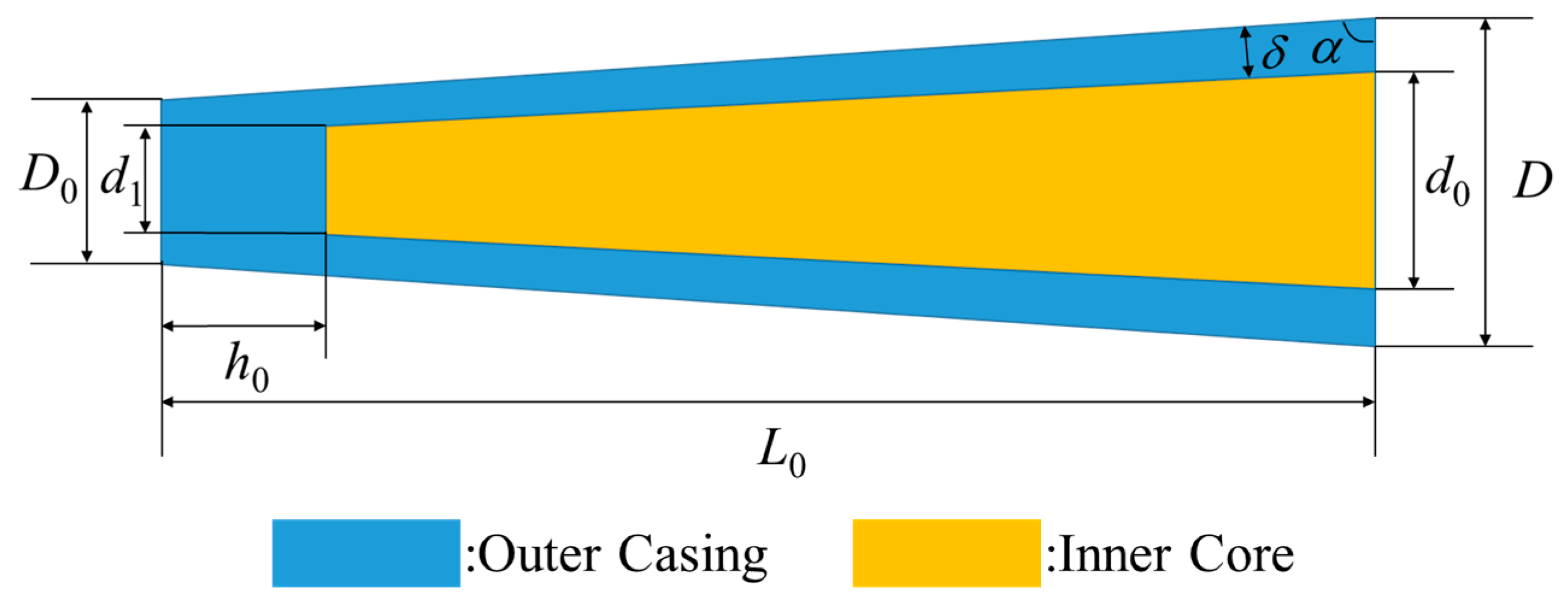
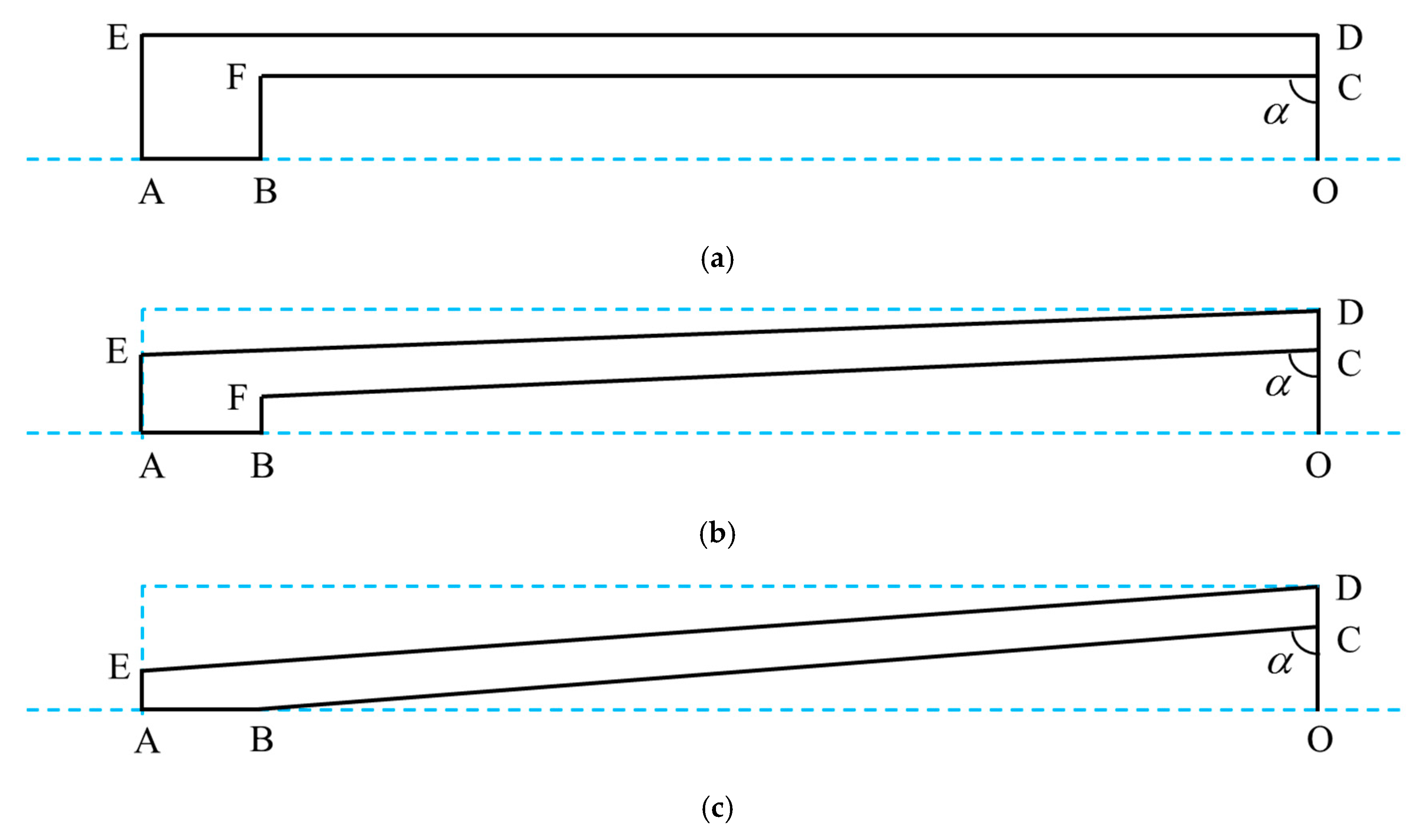
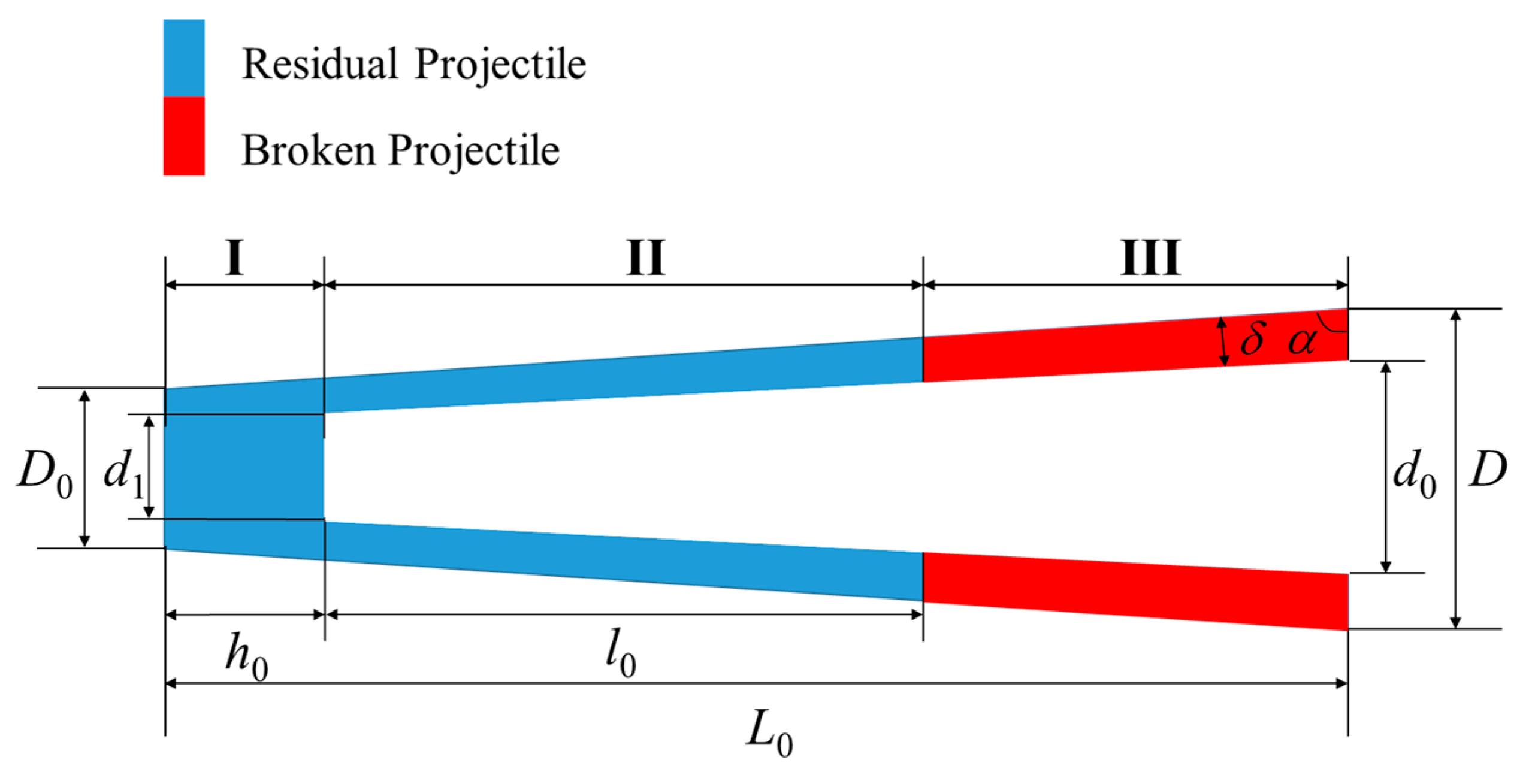
Next, the relationship between the fragment conversion rate and the residual length of the two different types of PELE projectile will be established respectively. In order to analyze the fragment conversion rate intuitively, the entire projectile body is divided into three parts: Projectile rear, unbroken hollow casing, and broken hollow casing which has been converted into fragments. The simplified diagrams of the failed conventional PELE projectile and the truncated cone-shaped PELE projectile are shown in Figure 8 and Figure 9, respectively.
Define the residual length of the projectile after penetrating the target plate as x, the residual length is x = h + l for the conventional PELE projectile, and the residual length is x = h0 + l0 for the truncated cone-shaped PELE projectile. Then, the expressions of the fragment conversion rate η of the two different types of PELE projectile can be obtained as follows.
Conventional PELE projectile:
M casing = M I + M II + M III
{ M I = π 4 ρ casing D 2 h M II = π 4 ρ casing ( D 2 d 2 ) l
η = M III M casing = 1 ( M I + M II M casing )
Truncated cone-shaped PELE projectile:
M casing = M I + M II + M III
{ M I = π 3 ρ casing [ ( h 0 cot α + D 0 2 ) 2 ( D 0 2 tan α + h 0 ) D 0 3 8 tan α ] M II = π 24 ρ casing tan α { [ D 0 + 2 ( h 0 + l 0 ) cot α ] 3 ( D 0 + 2 h 0 cot α ) 3 [ D 0 + 2 ( h 0 + l 0 ) cot α 2 δ / sin α ] 3 + d 1 3 }
η = M III M casing = 1 ( M I + M II M casing )
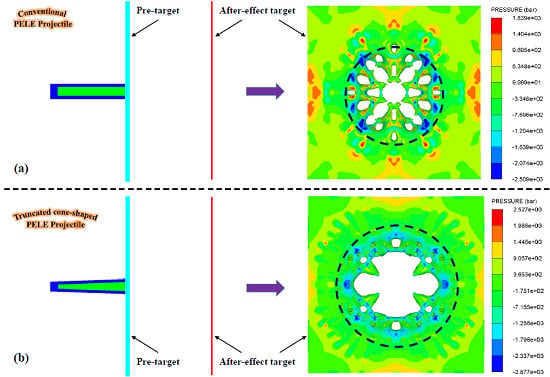
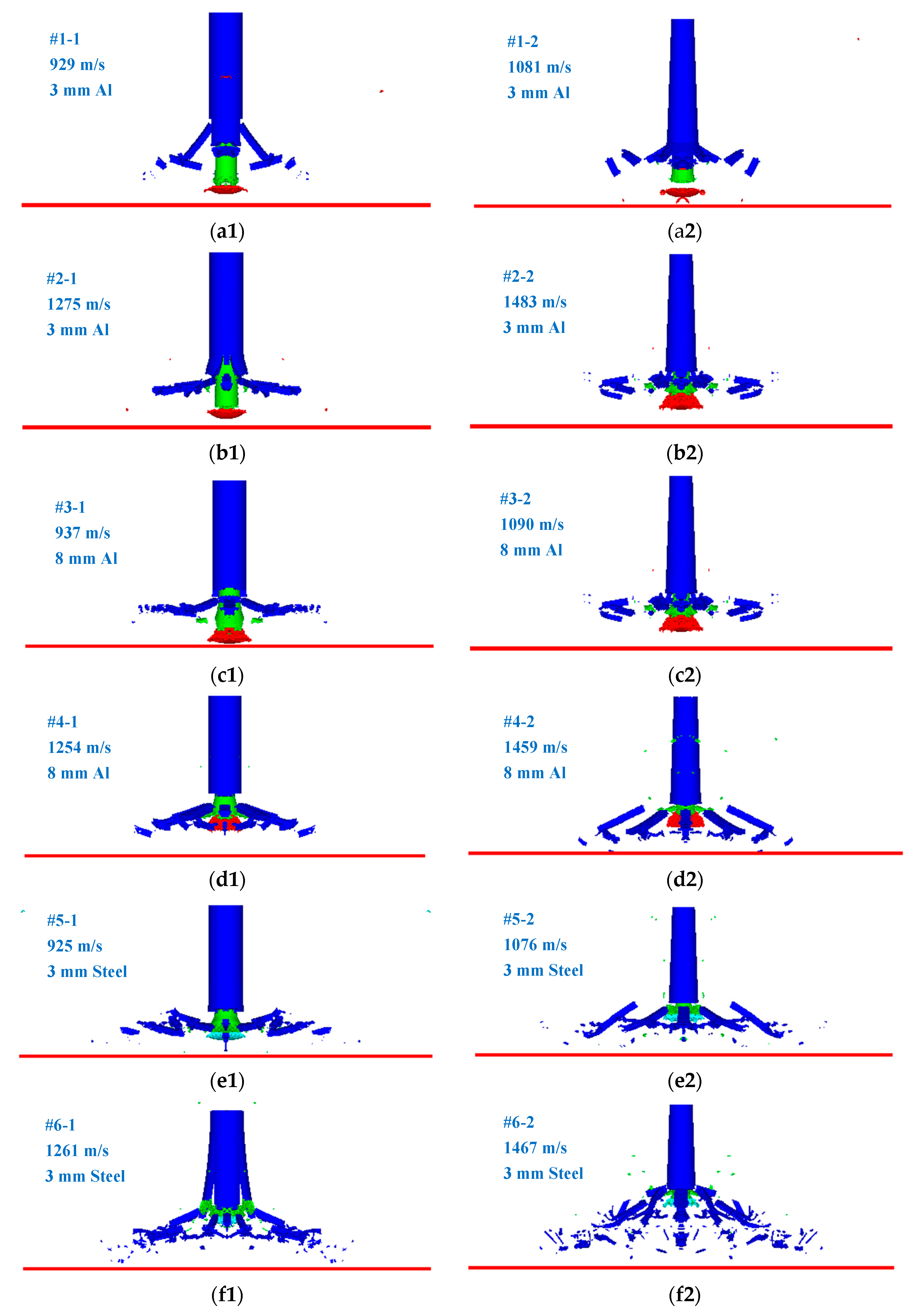
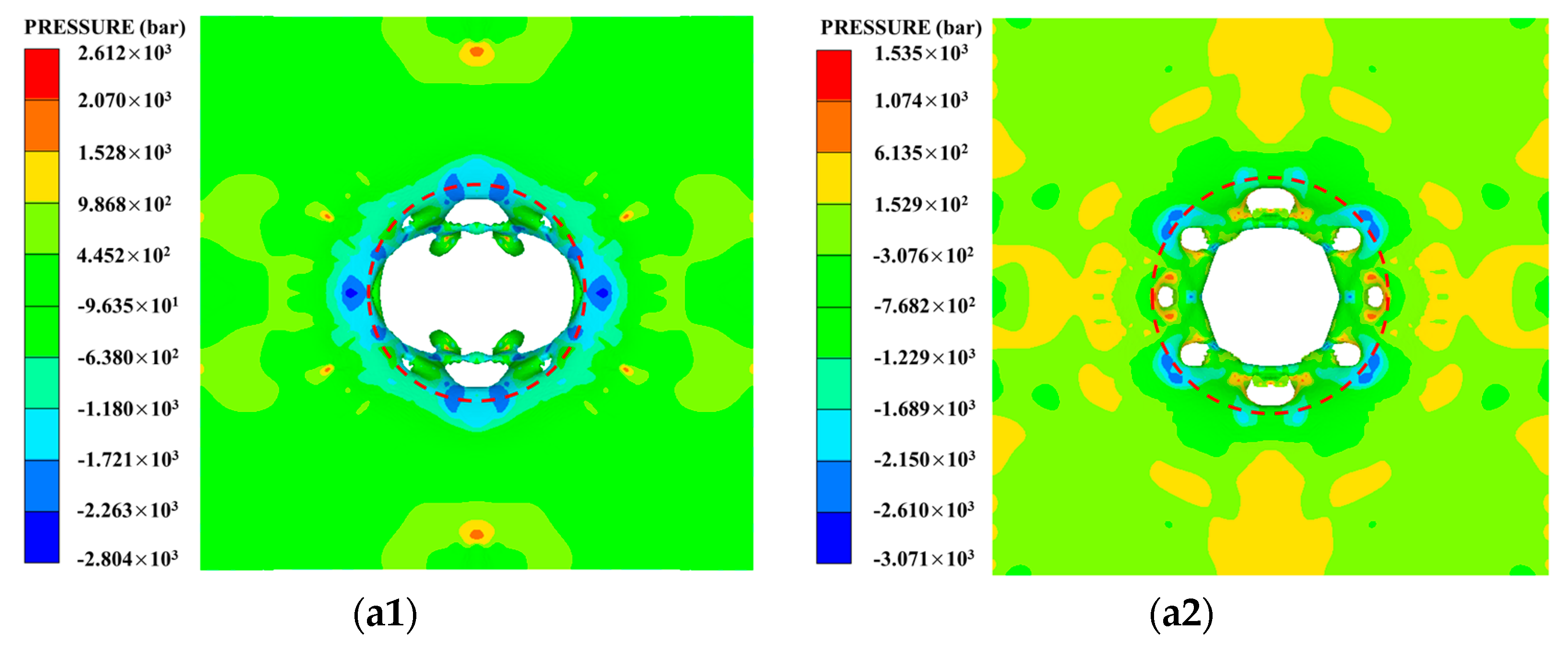
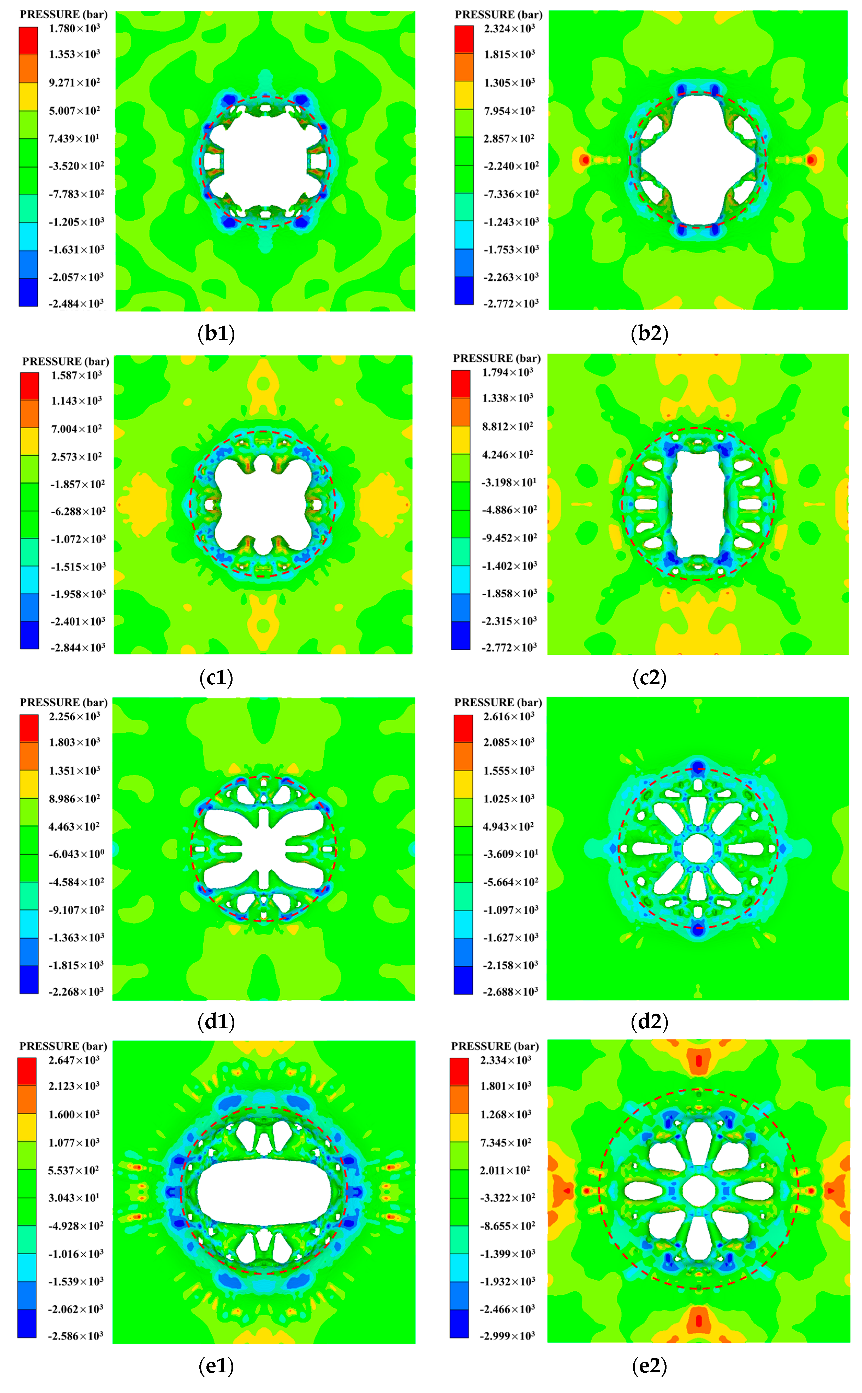
After the PELE projectile perforates the target plate, the outer casing will gradually expand to fracture under the continuous extrusion of the target plug. Under the action of radial force and inertial force, the fragments formed by the outer casing will have radial dispersion velocity, so the damage area formed by the fragments will gradually expand and stabilize with the axial movement of fragments. After analyzing the numerical simulation results, the fragments corresponding to the six sets of working conditions have been fully expanded before reaching the after-effect target. Thus, the status of projectile before impacting the after-effect target is given in this section, as shown in Figure 10. From Figure 10, the residual length of the truncated cone-shaped PELE projectile and the conventional PELE projectile before impacting the after-effect target can be qualitatively observed, and then the fragment conversion rate of the projectile can be roughly estimated. In addition, it can also be found that the fragment size and the fragment dispersion form of the two types of projectiles are also different. The fragments of the truncated cone-shaped PELE projectile are larger and more scattered, while the fragments of conventional PELE projectile are smaller and more concentrated. Therefore, it can be qualitatively predicted that the damage area radius of the truncated cone-shaped PELE projectile to the after-effect target is larger than that of the conventional PELE projectile. Of course, this conclusion is subject to confirmation from the quantitative analysis below.
At the same time, the axial residual lengths of the projectile body corresponding to several working conditions were counted, and the fragment conversion rates corresponding to different working conditions were also calculated according to the formulas of fragment conversion rate (Formula (19)–Formula (24)), as shown in Table 6.
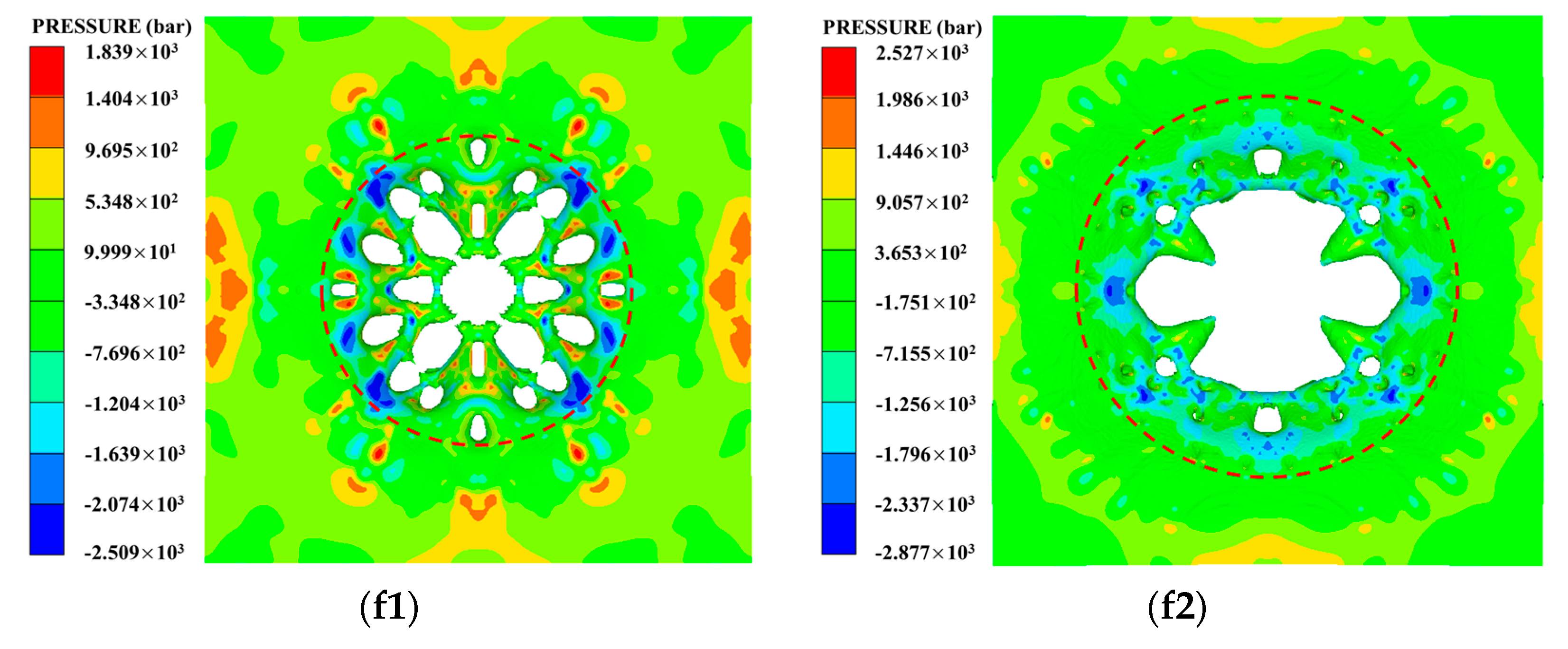
The fragment conversion rate of the PELE projectile is an important index to measure fragment effect; the size (mass) of the fragment and the radial velocity of the fragment should be taken into account in the evaluation of target damage level. If the fragment conversion rate of the projectile is higher but the radial velocity of fragment is lower, the fragment group will be relatively concentrated in the circumferential direction, so that the damage area radius of the target plate is smaller. Similarly, if the fragment conversion rate of the projectile is higher but the fragment size (mass) is smaller, the perforation area of the target plate is smaller, which is also not conducive to improving the damage level. Therefore, the target damage situations of each group of working conditions were analyzed, and the corresponding target damage diagrams of each group of working conditions were obtained as shown in Figure 11. Since the working conditions studied in this section involve different projectile velocities, different target materials, and different target thickness, the damage area radius of target was regarded as the main criterion in the analysis of target damage rather than the perforation area of target. In addition, R is defined to represent the damage area radius of the after-effect target, the damage area of the target is marked with red dotted circle, and the pits and perforations of the target plate were both regarded as damage to the target. The damage area radius of each working condition in Figure 11 was counted, as shown in Table 7.
Obviously, the two important parameters (fragment conversion rate η and damage area radius R) have been obtained, as shown in Table 6 and 
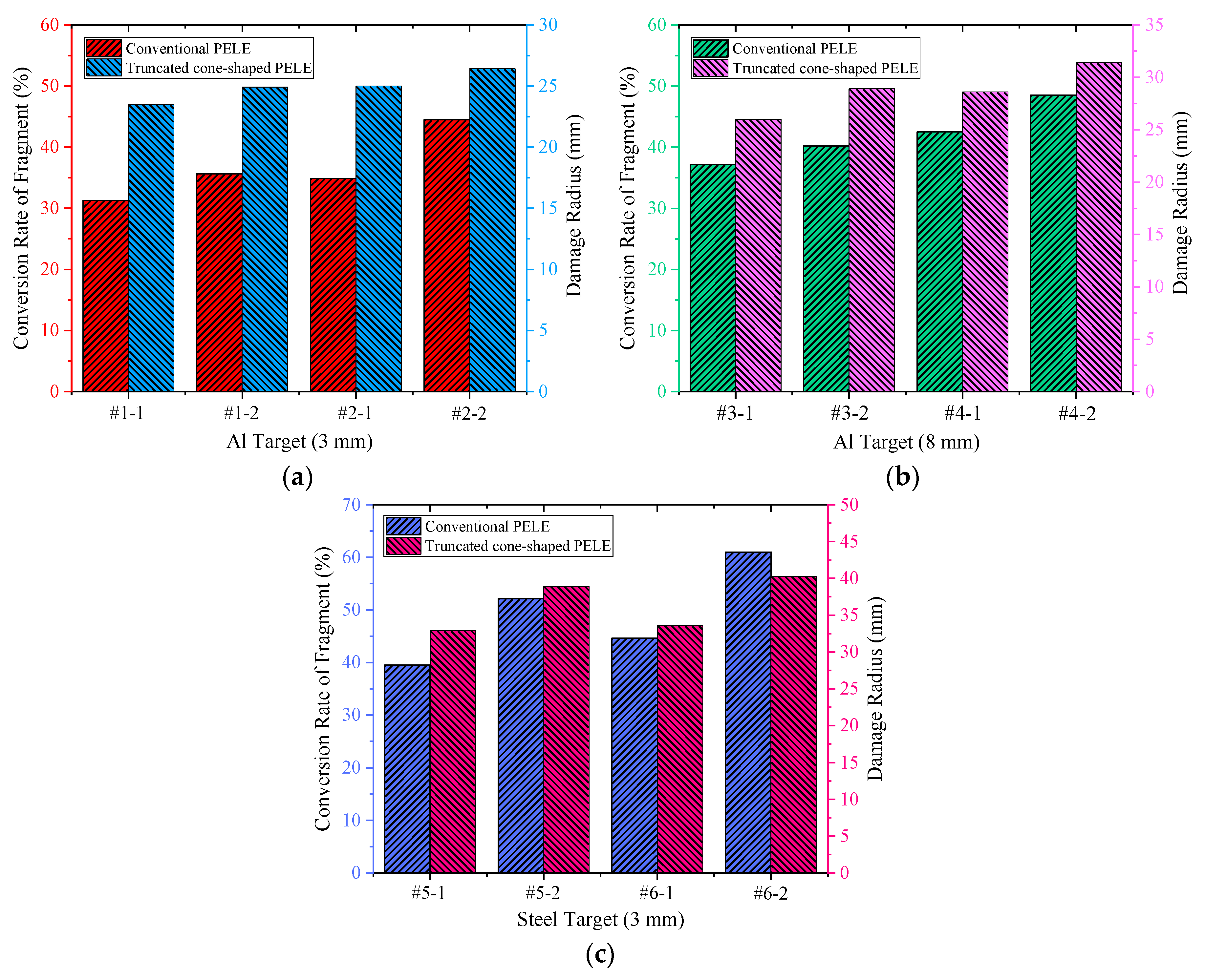
Table 7. In order to better compare and analyze the fragmentation effect of the truncated cone-shaped PELE projectile and the conventional PELE projectile, the fragment conversion rate and damage area radius corresponding to each working condition were integrated and compared, as shown in Figure 12.
From the histogram shown in Figure 12, it can be seen that under the condition of the same initial kinetic energy of projectile and the same thickness and material of the target plate, the fragment conversion rate η and the damage area radius R of the truncated cone-shaped PELE projectile are obviously larger than that of the conventional PELE projectile. The above phenomenon can be explained from the following two aspects.
(1) Under the same initial kinetic energy, the mass of truncated cone-shaped PELE projectile is slightly less than that of conventional PELE projectile, so the initial velocity of truncated cone-shaped PELE projectile is slightly higher than that of conventional PELE projectile. The radial dispersion velocity of fragments is positively correlated with the axial velocity of the projectile body.
(2) According to the design idea of truncated cone-shaped PELE projectile, the angle between the busbar and axis of the truncated cone-shaped PELE projectile is greater than 0°, which means that the fragments have an initial deflection angle greater than 0° before formation. As a result, the deflection angle of the fragments during the actual scattering process are greatly improved to some extent.
According to the action mechanism of the PELE projectile, the fragments generated during the penetration process will obtain radial velocity, and the larger the radial velocity and deflection angle, the larger the damage radius of fragments. In short, the above results indicate that the fragmentation effect of the truncated cone-shaped PELE projectile is better than that of the conventional PELE projectile.

5. Conclusions

In order to improve the damage level of PELE projectile to the after-effect target, this paper hopes to achieve this goal by changing the structural shape of PELE projectile. For this reason, the truncated cone-shaped PELE projectile was designed, and a series of simulation conditions were formulated accordingly. The penetration ability and fragmentation effect of the conventional PELE projectile and the truncated cone-shaped PELE projectile were compared and analyzed, and the following conclusions were drawn:
1)
In order to facilitate the comparative analysis with the conventional PELE projectile, the design principle of the truncated cone-shaped PELE projectile is to ensure that the four indexes of the impact end (projectile head), the length-diameter ratio of projectile, the thickness of outer casing and the sealing thickness of projectile rear are the same. Based on the structural parameters of the PELE projectile given in this paper, the range of angle α of the truncated cone-shaped PELE projectile was determined to be 86.2°–90°.
2)
There is little difference in penetration ability between the conventional PELE projectile and the truncated cone-shaped PELE projectile. In fact, the kinetic energy loss of the truncated cone-shaped PELE projectile is slightly larger, but it can be reasonably explained. According to the penetration resistance formulas, with the increase of impact velocity, the penetration resistance will increase, the corresponding energy consumption or the kinetic energy loss of projectile will increase. The impact velocity of the truncated PELE projectile is higher under the same initial kinetic energy condition, which means that the kinetic energy loss of the truncated cone-shaped PELE projectile must be slightly larger.
3)
If the initial kinetic energy of the projectile and the thickness and material of the target plate is consistent, the fragment conversion rate η and the damage area radius R of the truncated cone-shaped PELE projectile are obviously larger. In other words, the results indicate that the fragmentation effect of the truncated cone-shaped PELE projectile is better than that of the conventional PELE projectile.
4)
In summary, the damage power of the truncated cone-shaped PELE projectile is better than that of the conventional PELE projectile. Therefore, the results show that the design idea of applying the truncated cone-shaped structure to the PELE projectile is feasible and reasonable. The conclusions lay a foundation for further exploring the relationship between the optimum angle α and the material and thickness of the target.

Author Contributions

Conceptualization, L.D. and W.T.; methodology, X.R.; validation, L.D. and J.Z.; formal analysis, J.Z.; resources, X.R.; data curation, J.Z.; writing—original draft preparation, L.D.; writing—review and editing, W.T.; supervision, X.R.; project administration, W.T.

Funding

This research was funded by the National Natural Science Foundation of China (grant Nos. 11002162 and 11072262).

Conflicts of Interest

The authors declare no conflicts of interest.

References

  1. Kesberg, G.; Schirm, V.; Kerk, S. PELE—The future ammunition concept. In Proceedings of the 21st International Symposium on Ballistics (ISB’21), Adelaide, Australia, 19–23 April 2004. [Google Scholar]
  2. Paulus, G.; Chanteret, P.Y.; Wollmann, E. PELE: A new penetrator-concept for the generation of lateral effects. In Proceedings of the 21st International Symposium on Ballistics (ISB’21), Adelaide, Australia, 19–23 April 2004. [Google Scholar]
  3. Rheinmetall Waffe Munition. 105/120/125 mm PELE Firing Results. Available online: https://ndiastorage.blob.core.usgovcloudapi.net/ndia/2005/garm/wednesday/borngen.pdf (accessed on 12 July 2019).
  4. Gloude, D. Capabilities of Penetrator with Enhanced Lateral Efficiency. Available online: https://ndiastorage.blob.core.usgovcloudapi.net/ndia/2007/gun_missile/GMTueAM1/GloudePresentation.pdf (accessed on 12 July 2019).
  5. Paulus, G.; Schirm, V. Impact behavior of PELE projectiles perforating thin target plates. Int. J. Impact Eng. 2006, 33, 566–579. [Google Scholar] [CrossRef]
  6. Ding, L.; Zhou, J.; Tang, W.; Ran, X.; Hu, Y. Impact energy release characteristics of PTFE/Al/CuO reactive materials measured by a new energy release testing device. Polymers 2019, 11, 149. [Google Scholar] [CrossRef] [PubMed]
  7. Du, Z.; Song, L.; Zhong, K.; Wang, F. Influence of the ratio of inner to outer diameter on penetrator with enhanced lateral efficiency. J. Comput. Theor. Nanosci. 2011, 4, 1525–1528. [Google Scholar] [CrossRef]
  8. Zhu, J.; Zhao, G.; Du, Z.; Li, D. Experimental study of the influence factors on small caliber PELE impacting thin target. Chin. J. Exp. Mech. 2007, 22, 505–510. [Google Scholar]
  9. Tu, S.; Wang, J.; An, Z.; Chang, Y. Influence of thickness of armor on the burst-effect of steel shell PELE. In Proceedings of the 9th International Conference on Electronic Measurement & Instruments, Beijing, China, 16–19 August 2009. [Google Scholar]
  10. Fan, Z.; Ran, X.; Tang, W.; Ke, Y.; Li, Z. The model to calculate the radial velocities of fragments after PELE perforating a thin plate. Int. J. Impact Eng. 2016, 95, 12–16. [Google Scholar] [CrossRef]
  11. Verreault, J.; Hinsberg, N.; Abadjieva, E. PELE fragmentation dynamics. In Proceedings of the 27th International Symposium on Ballistics (ISB’27), Freiburg, Germany, 22–26 April 2013. [Google Scholar]
  12. Verreault, J. Modeling of the PELE fragmentation dynamics. In Proceedings of the 18th Biennial International Conference of the APS Topical Group on Shock Compression of Condensed Matter held in Conjunction with the 24th Biennial International Conference of the International Association for the Advancement of High Pressure Science and Technology, Seattle, WA, USA, 7–12 July 2013. [Google Scholar]
  13. Verreault, J. Analytical and numerical description of the PELE fragmentation upon impact with thin target plates. Int. J. Impact Eng. 2015, 76, 196–206. [Google Scholar] [CrossRef]
  14. Century Dynamics Inc. Interactive Non-Linear Dynamic Analysis Software AUTODYN User Manual; Century Dynamics Inc.: Oakland, CA, USA, 2003. [Google Scholar]
  15. Ding, L.; Zhou, J.; Tang, W.; Ran, X.; Cheng, Y. Research on the crushing process of PELE casing material based on the crack-softening algorithm and stochastic failure algorithm. Materials 2018, 11, 1561. [Google Scholar] [CrossRef] [PubMed]
  16. Bedon, C.; Kalamar, R.; Eliášová, M. Low velocity impact performance investigation on square hollow glass columns via full-scale experiments and Finite Element analyses. Compos. Struct. 2017, 182, 311–325. [Google Scholar] [CrossRef]
Figure 1. Simplified diagrams of the conventional PELE (penetrator with enhanced lateral efficiency) projectile structure.
Symmetry 11 01025 g001
Figure 2. Simplified diagrams of the truncated cone-shaped PELE projectile structure.
Symmetry 11 01025 g002
Figure 3. Geometric structure of the truncated cone-shaped PELE projectile with different angle α. (a) α = 90°; (b) α = 88°; (c) α = 86.2°.
Symmetry 11 01025 g003
Figure 4. Schematic diagram of the finite element model.
Symmetry 11 01025 g004
Figure 5. Schematic diagram of penetration process of the conventional PELE projectile and the truncated cone-shaped PELE projectile corresponding to #5 working condition. (a1~d1): Conventional PELE projectile; (a2~d2): Truncated cone-shaped PELE projectile. (a1) t = 0 µs; (a2) t = 0 µs; (b1) t = 47 µs; (b2) t = 40 µs; (c1) t = 126 µs; (c2) t = 108 µs; (d1) t = 174 µs; (d2) t = 148 µs.
Symmetry 11 01025 g005
Figure 6. Local enlargement diagrams of the conventional PELE projectile and the truncated cone-shaped PELE projectile penetrating the target plate. (a) Conventional PELE projectile; (b) truncated cone-shaped PELE projectile.
Symmetry 11 01025 g006
Figure 7. Histogram of kinetic energy loss of the conventional PELE projectile and the truncated cone-shaped PELE projectile penetrating the target plate. (a) 3 mm Al target plate; (b) 8 mm Al target plate; (c) 3 mm steel target plate.
Symmetry 11 01025 g007
Figure 8. Simplified diagram of the failed casing of conventional PELE projectile.
Symmetry 11 01025 g008
Figure 9. Simplified diagrams of the failed casing of truncated cone-shaped PELE projectile.
Symmetry 11 01025 g009
Figure 10. The status of two different types projectile before impacting the after-effect target. (a1f1): Conventional PELE projectile; (a2f2): Truncated cone-shaped PELE projectile.
Symmetry 11 01025 g010
Figure 11. After-effect target damage situation corresponding to different working conditions. (a1) #1-1 (3 mm Al–929 m/s); (a2) #1-2 (3 mm Al–1081 m/s); (b1) #2-1 (3 mm Al–1275 m/s); (b2) #2-2 (3 mm Al–1483 m/s); (c1) #3-1 (8 mm Al–937 m/s); (c2) #3-2 (8 mm Al–1090 m/s); (d1) #4-1 (8 mm Al–1254 m/s); (d2) #4-2 (8 mm Al–1459 m/s); (e1) #5-1 (3 mm steel–925 m/s); (e2) #5-2 (3 mm steel–1076 m/s); (f1) #6-1 (3 mm steel–1261 m/s); (f2) #6-2 (3 mm steel–1467 m/s).
Symmetry 11 01025 g011aSymmetry 11 01025 g011bSymmetry 11 01025 g011c
Figure 12. Comparison of the fragment conversion rate and damage area radius under different working conditions. (a) 3 mm Al target plate; (b) 8 mm Al target plate; (c) 3 mm steel target plate.
Symmetry 11 01025 g012
Table 1. Structural parameters of the truncated cone-shaped PELE projectile with α = 88°.
DD0d0d1Lhδ
10 mm6.6 mm6 mm2.8 mm50 mm5 mm2 mm
Table 2. Initial velocity of the two different types of PELE projectiles.
Condition NumberM (g) v (m/s)M′ (g)v′ (m/s)
#151.492938.01081
#212751483
#39371090
#412541459
#59251076
#612611467
Table 3. Material parameters in the numerical simulation.
VariableMaterial
TungstenAl-6061Al-7075Steel-4340
ρ0 (g/cm3)182.652.87.823
c0 (km/s)4.035.245.24.57
s1.2371.41.361.49
Grüneisen Coefficient--1.97----
Cp (J/kg∙K)--885----
Shear Modulus G (GPa)139.0227.526.777
Yield Stress Y (GPa)1.50.30.40.8
Principle Tensile Stress σT (GPa)2.80.5----
Principle Tensile Strain εT0.035------
Fracture Energy Gf (J/m2)45------
Stochastic Variance γ36.5------
Inst. Geometric Strain0.60.8FailureFailure
Table 4. Simulation condition.
Condition NumberInner Core MaterialTarget Plate MaterialTarget Plate ThicknessAfter-Effect Target MaterialAfter-Effect Target ThicknessImpact Velocity
#1AlAl3 mmAl1 mm1081 m/s
#2Al3 mm1483 m/s
#3Al8 mm1090 m/s
#4Al8 mm1459 m/s
#5Steel3 mm1076 m/s
#6Steel3 mm1467 m/s
Table 5. Kinetic energy loss of the two different types of PELE projectile.
Condition NumberProjectile TypeInitial Kinetic Energy of Projectile (KJ)Residual Kinetic Energy of Projectile (KJ)Kinetic Energy Loss of Projectile (KJ)
#1-1Conventional22.220.71.5
#1-2Truncated cone-shaped22.020.31.7
#2-1Conventional41.939.12.8
#2-2Truncated cone-shaped41.338.33.0
#3-1Conventional22.618.93.7
#3-2Truncated cone-shaped22.318.43.9
#4-1Conventional40.535.15.4
#4-2Truncated cone-shaped40.034.25.8
#5-1Conventional22.120.02.1
#5-2Truncated cone-shaped21.819.32.5
#6-1Conventional41.037.23.8
#6-2Truncated cone-shaped40.436.53.9
Table 6. Mass loss and fragment conversion rate of the two different types of PELE projectile.
Condition NumberProjectile TypeResidual Length of Projectile (mm)Mass Loss of Outering Casing (g)Fragment Conversion Rate (%)
#1-1Conventional29.216.131.3
#1-2Truncated cone-shaped35.320.335.6
#2-1Conventional25.117.934.9
#2-2Truncated cone-shaped31.038.344.5
#3-1Conventional32.719.137.2
#3-2Truncated cone-shaped33.118.440.2
#4-1Conventional29.721.842.5
#4-2Truncated cone-shaped29.034.248.5
#5-1Conventional31.420.339.5
#5-2Truncated cone-shaped27.219.352.1
#6-1Conventional28.522.944.6
#6-2Truncated cone-shaped22.536.561.0
Table 7. Damage area radius of the two different types of PELE projectile.
Condition NumberProjectile TypeImpact Velocity (m/s)Target Plate TypeDamage Area Radius R (mm)
#1-1Conventional9293 mm/Al23.5
#1-2Truncated cone-shaped108124.9
#2-1Conventional127525.0
#2-2Truncated cone-shaped148326.4
#3-1Conventional9378 mm/Al26.0
#3-2Truncated cone-shaped109028.9
#4-1Conventional125428.6
#4-2Truncated cone-shaped145931.4
#5-1Conventional9253 mm/steel32.9
#5-2Truncated cone-shaped107638.9
#6-1Conventional126133.6
#6-2Truncated cone-shaped146740.3

