1. Introduction
Usually filtering and sampling devices for analog signal processing are represented by asymptotically stable systems.
The filtering properties of these systems are determined by their transfer function. Thus, a filtering device represented by a low-pass filter of first order with the transfer function
provides attenuation for an alternating signal with angular frequency
ω >
ω0 = 1/
T0 of about
ω/
ω0 times. A filtering device represented by a low-pass filter of second order with the transfer function
provides a higher attenuation of about (
ω/
ω0)
2 times for an alternating signal with angular frequency
ω >
ω0 = 1/
T0.
For a symmetrical second order system (generating undamped oscillations symmetrical as related to the time moment corresponding to a maximum) the transfer function is represented by
This system attenuates an alternating input of angular frequency
ω about (
ω/
ω0)
2 times (where
ω0 = 1/
T0). By integrating these undamped symmetrical oscillations on the time interval (0, 2
πT0), a supplementary attenuation of about (2
πω/
ω0) is obtained. Moreover, in case of a unity-step input the quantity to be integrated equals zero at the end of the integration period, (see [
1] for details).
Thus, the influence of the random variations of the integration period (generated by the switching phenomena) is practically rejected. Overall, this structure provides an attenuation of about (2π)(ω/ω0)3 for an alternating input of angular frequency ω on the time interval 2πT0 = 2π/ω0.
More advanced mathematical models for detecting sharp jumps (as wavelets methods presented in [
2]) are hard to be implemented for fast analog signal processing.
However, the use of any integrative method requires some supplementary analog devices (as operational amplifiers) to be added. As it is well known, these devices should be calibrated in an accurate manner, so (if possible) their number should be reduced.
To do this, we shall try to design a structure for a robust sampling procedure based on generated symmetrical (undamped) oscillations without any additional integrative stage (similar to aspects of generating asymmetrical pulses presented in [
3]).
Such an accurate structure could be useful for detecting short-step pulses (as in [
4]), for accurate image processing (as in [
5]), or for preliminary signal processing before advanced mathematical techniques as wavelets to be applied for an optimal control [
6].
2. Materials and Methods
Let us analyze in detail the response of a second order oscillating system at a unity-step input. For the transfer function represented by Equation (3), the response would be
It can be noticed that the first-time moment (excepting the initial moment of time) when the slope of y(t) is zero corresponds to t′ = πT0, the value of y(t) being two (double as related to the amplitude of the step input). Therefore, a robust sampling procedure could act at this time moment.
For an alternating input with angular frequency ω, the amplitude of the generated output with this angular frequency ω will be (ω/ω0)2 lower than the amplitude of the alternating input (according to partial fraction decomposition applied to generated output within Laplace transform theory).
Since a non-vanishing term with angular frequency ω0 is also generated (corresponding to proper oscillation of the undamped second order system), we must take care that this alternating component should be added at the sampling time moment to the attenuated output of angular frequency ω. In fact, two alternating terms sin(ω0t) and cos(ω0t) of angular frequency ω0 are generated, but sin(ω0t) equals zero for ω0t = π (the suggested sampling moment of time). For null initial conditions, its amplitude corresponds to the opposite value of the oscillating output of angular frequency ω at zero moment of time. Since this has been attenuated (ω/ω0)2 times (as shown before), the sum of these two alternating components (the attenuated component of angular frequency ω and the cosine term cos(ω0t) of the proper oscillation required for compensating this component at zero moment of time) cannot be greater than two times the amplitude of the attenuated component of angular frequency ω.
Thus it can be preliminary considered that a second order oscillating system working on half-period from initial null conditions could provide a robust sampling procedure for a step input (doubling its amplitude at the sampling time moment) and attenuation for an alternating component of angular frequency ω of about (ω/ω0)2/2.
3. Results
Let us consider a second order system described by the differential equation
where
u(
t) corresponds to the received signal (the input), and
f(
t) corresponds to the generated output.
First, we analyze the case when the input is represented by an alternating signal of angular frequency
ω, amplitude
A and initial phase
φ. In this case, the output
falt(
t) is represented by an alternating function denoted as
falt(
t). This means
Considering null initial conditions, the output
falt(
t) for this standard linear differential equation will be represented by
The sampling moment of time
tS is chosen at half-period. This means
Thus, the function
falt(
t) generated by the second order oscillating system for
t =
tS would be
(
cos(
ω0 tS) = −1,
sin(
ω0 tS) = 0 were substituted in Equation (7) according to Equation (8)).
The first two terms in Equation (9) can be grouped according to
and
falt(
tS) can be written as
Since
it results that
So
Thus, for the modulus of the left-hand side of Equation (11) it can be written the inequality
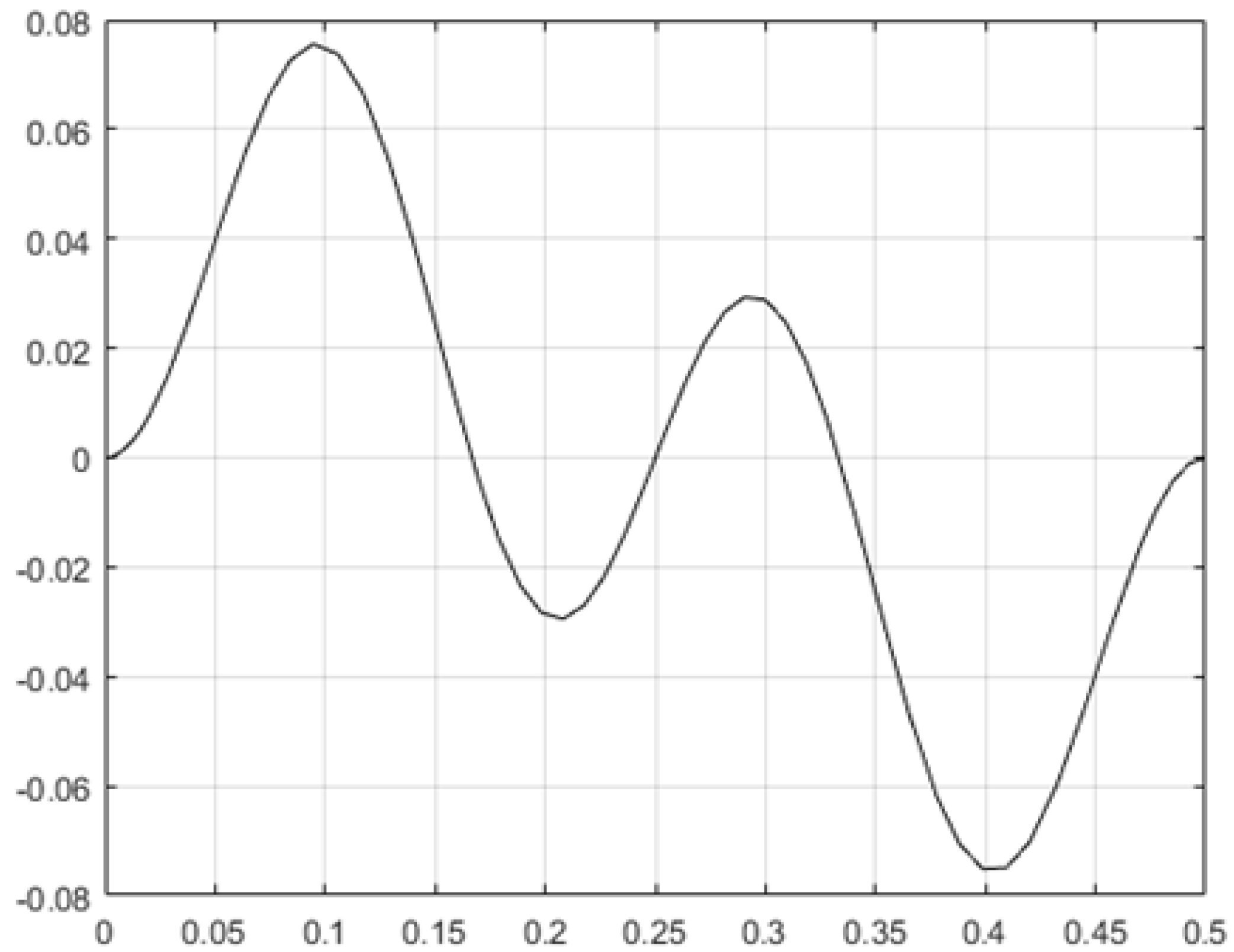
The response of a second order oscillating system (with a time period which equals unity) on a half-period interval, for an input represented by an alternating function with unity amplitude and angular frequency five times greater, is represented in
Figure 1. The amplitude of the generated output is less than 0.08, which means about 2/(5
2) times less than input amplitude (the validity of Equation (15) being confirmed).
It should be noticed that there is no symmetry as related to a certain vertical axis corresponding to a local maximum since generated oscillations of higher frequency are overlapped to a slow-varying alternating function of unity period.
Let us now consider the case when the input
u(t) of the second order oscillating system described by the differential Equation (5) is represented by a step input of amplitude
A0. This means
There are considered initial null conditions for
t = 0, as in Equation (6). The function
f0(
t) generated by this step signal is represented by
where
ω0 = 1/
T0.
The sampling moment of time corresponds to half period. This means
and thus,
It results in the value of
f(t) at the sampling moment of time as
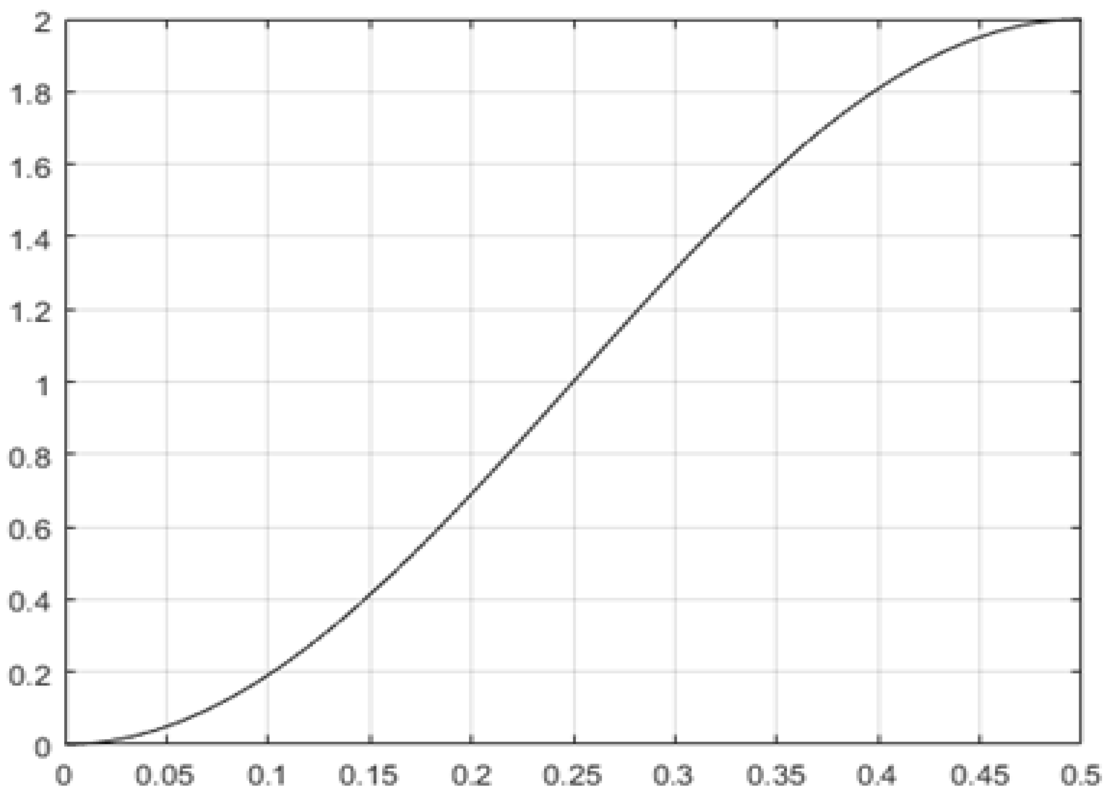
It must be emphasized the fact that f0(t) possess a saddle point at this sampling time moment (its derivative presents a null value). Thus, a robust sampling procedure can be performed, the filtering and sampling structure being insensitive at small variations of the sampling moment of time.
The response of a second order oscillating system (with a time period which equals unity) on a half-period interval, for a unity-step input, is represented in
Figure 2. The sampling moment of time is chosen at half-period, so the symmetry as related to the vertical axis represented at
t = 0.5 cannot be noticed.
Finally, let us consider the case when the input of the oscillating system is represented by a sum of a step-input of amplitude A0 and an alternating signal of angular frequency ω and amplitude A (the order of magnitude for A and A0 being the same). An example could be represented by measurements of angular velocity based on the rectification of an alternating signal generated through electromagnetic induction (a significant alternative component being added to the constant component proportional to the angular velocity).
Thus,
Since the oscillating system presented in Equation (5) is linear, the output would be simply represented by the sum
So,
The term f0(tS) corresponds to the useful signal (proportional to the step input of amplitude A0) necessary to be sampled; the term falt(tS) is generated by the alternating signal of angular frequency ω necessary to be filtered (its magnitude should be as less than possible).
According to Equations (15) and (20), it results
which can be also written as
The reverse of this ratio is
corresponds to the signal-to-noise ratio of this filtering and sampling system. Since the time period
T0 of this oscillating second order system would be at least several times greater than the period
T of the alternating input component to be filtered, it results that
Thus,
Finally, the signal-to-noise ratio of this filtering and sampling second order system corresponds to
The inequality represented in Equation (29) shows that the input signal-to-noise ratio
(the ratio of amplitude of step input to amplitude of alternating input) is improved {(
T0/
T)
2 − 1
} times so as to obtain the output signal-to noise-ratio
(the ratio of modulus of sampled output generated by step input to the modulus of sampled output generated by alternating input).
The sampling moment of time being established at half-period, it results that a response time
Tr of
can be considered for this oscillating system working on half-period.
After each working time of half-period, the initial null conditions should be restored before a new working time to start. Thus, possible instabilities due to the use of a second order system without damping on extended time intervals can be avoided.
4. Discussion
For an efficient attenuation of an alternating input of period T is necessary that the time constant T0 of any second order oscillating system used for filtering to be several times greater than T (it should include several periods of this oscillating input). Preliminary we denote this required number by N.
This means
T0 =
N T,
T0/
T = N, so
(the accuracy of approximation above being higher than 96% for
N > 5). Thus, it can be considered that a filtering device based on an oscillating system working on half period improves the signal-to-noise ratio as
(usually,
N equals 4…6 so (
T0/
T)
2 is much greater than unity in right-hand-side of (29)), with the response time
For a method based on the integration of an oscillating second order system on a period (this means on 2
πT0), the working time
Tr(i) equals
Since the signal-to-noise ratio for this system based on integration is represented by
(according to [
2]), by substituting
ω0 = 1/
T0,
ω = 1/
T in Equation (37) it results
If a damped second order system would have been used, the response time would have been
Tr(d) = 4
T0/
ξ. The time constant
T0 is considered to include the same number
N of periods of the oscillating input (with amplitude
A and angular frequency
ω). Thus
An alternating input signal of angular frequency
ω is attenuated about (
ω/
ω0)
2 times (according to the basic theory of second order systems for
ω much greater than
ω0), so the signal-to-noise ratio for a damped second order system is
Using
T0/
T = N it results
By comparing Equations (34) and (41) by one side, and Equations (35) and (39) by the other side, it results that an oscillating second order system working on half-period presents a signal-to-noise ratio about four times greater than a damped second order system, within a shorter response time (for the same time constant). By comparing Equations (34) and (37) it results that its signal-to-noise ratio is much lower than the ratio of a second order oscillating system based on integration. However, the lack of the integrator electronic circuit corresponds to a more robust structure working on a time interval reduced to 50% (according to Equations (34) and (35)). Thus, the filtering performances of an oscillating system working on half-period should be preliminarily checked before a supplementary integrator circuit (usually based on operational amplifiers) to be added. For T0/T = 5 and A = A0 = 1 (a significant alternating input) it results an alternating output (the noise) less than 1% (the same order of magnitude as for the error of the step output considered on the transient time interval of first or second order damped systems), according to Equations (33) and (34).
