Article

An Efficient Algorithm for mmWave MIMO Systems

1
Department of Electrical Engineering, University of Engineering & Technology, Peshawar 814, Pakistan
2
Department of Electrical Engineering, College of Electronics and Information Engineering, Sejong University, 209 Neungdong-ro, Gwangjin-gu, Seoul 05006, Korea
3
Department of Information Technology, King Abdulaziz University, Jeddah 21589, Saudi Arabia
4
Department of Communications Engineering, Jilin University, Changchun 130012, China
*
Author to whom correspondence should be addressed.
Symmetry 2019, 11(6), 786; https://doi.org/10.3390/sym11060786
Submission received: 27 May 2019 / Revised: 10 June 2019 / Accepted: 11 June 2019 / Published: 13 June 2019

Abstract

:
Efficient and Symmetry based precoding plays a key role in wireless communications. In order to improve the transmission performance of multi-user millimeter wave Multiple-Input Multiple-Output (MIMO) (MU-mmWave MIMO) systems, this paper proposes an analog precoding scheme for the receiver of mmWave MIMO with split sub-array hybrid analog and digital architecture. Then, we propose a hybrid analog and digital precoding algorithm based on channel reciprocity (APoCR) to maximize the spectral efficiency by utilizing the triple joint optimization problem, which can be divided into the analog and digital part. The analog combination vectors (ACVs) are obtained by the signal-to-interference-and-noise ratio (SINR) reception maximization of each downlink user and the analog precoding vectors (APVs) are obtained by the SINR reception maximization of each uplink antenna array. The digital precoder of the transmitter is designed after the analog part optimization to alleviate the interference between multiple data streams of the users. The simulation results show that the proposed precoding algorithm has a better sum rate, fast convergence, and improved SINR than the other state-of-the-art algorithms.

1. Introduction

Multiple-Input Multiple-Output (MIMO) technology has widely been used in low-band Wireless Local Area Networks (WLAN) and cellular communication because it can break through the single-antenna system Shannon capacity. However, due to the limitation of spectrum resources, the existing low-band wireless communication has been unable to meet the increasing demand for wireless terminal connections and the urgent need for multi-gigabit data services. In order to solve the problem of low-band spectrum scarcity and further improve system capacity and improve user data experience, the spectrum-rich millimeter wave band has been paid increasing attention as the key spectrum of next-generation mobile communication technology [1,2]. The fifth-generation mobile communication (5G) plans to use the millimeter wave frequency band in the frequency range of 6 to 100 GHz to provide higher system capacity for users in hotspots [3,4,5,6,7,8], channel measurement and measurement in several important frequency bands such as 28 GHz, 38 GHz, and 73 GHz. Modeling is underway, and the IMT-2020 (5G) promotion group also released the 5G wireless technology architecture white paper in May 2015 [9]. For the 60 GHz band, the Institute of Electrical and Electronics Engineers (IEEE) released the wireless Local Area Network (LAN) standards IEEE802.15.3c [10] and IEEE 802.11ad [11] in 2009 and 2012, respectively, and IEEE 802.11ay as an enhancement to IEEE 802.11ad [12]. The version is also being determined. For the wireless LAN in China’s 45 GHz band, the IEEE802.11aj (45 GHz) standard development task force was formally established in 2012 [12], and the standard initial version will be released in early 2016. In the same propagation environment, the rain attenuation and oxygen absorption in the millimeter wave band are more serious than in the frequency band below 6 GHz [13], and the propagation path loss is higher. On the other hand, due to the small wavelength of the millimeter wave, the integration of large array antennas can be realized. Combining the array gain advantage of the array antenna with the precoding technology can effectively compensate for the loss of the millimeter wave propagation path and meet the transmission distance requirement. Considering the traditional digital precoding technology, each transmitting antenna corresponds to one radio frequency (RF) link. For a millimeter wave system using a large array antenna, hardware using digital precoding is costly and energy intensive. Affected by digital precoding power consumption and implementation of large complexity, the literature [14] proposed analog beamforming, through the constant mode phase shifter to adjust the phase of the transmitted signal. However, since the analog precoding vector elements are limited by the constant mode, the system performance is worse than the unrestricted digital precoding and is suitable for the single-stream transmission case, and the multi-stream or multi-user transmission is complicated. In order to solve the problem of hardware limitation and power consumption, and support multi-stream transmission, hybrid modulus precoding technology using only a limited number of RF links is proposed to achieve a compromise between hardware cost and system performance [15,16]. The hybrid modulus precoding maps the data to the respective RF links through the baseband digital precoding process at the transmitting end and then adjusts the phase of the signals on each RF link through the constant mode phase shifter to complete the analog precoding. According to the connection mode of the RF link and the transmitting antenna, the millimeter wave MIMO hybrid precoding system has two architectures of separate MIMO precoding and shared MIMO precoding [17]. For the specific architecture, see Section 2.1.
This paper considers the hybrid-modular precoding design of a millimeter wave MIMO system in a multi-user scenario. Many kinds of literature have studied the multi-user hybrid modulus precoding algorithm under the shared array MIMO architecture: [18] proposed a two-step precoding algorithm for designing an RF precoder and combiner based on maximizing the power of each user signal and solving digital precoding after determining RF precoding, but only considering a single path channel and based on quantization code. The algorithm requires a large amount of codeword training overhead. In [19], a hybrid precoding method is proposed to maximize the minimum signal-to-interference-and-noise ratio on each subcarrier. It does not consider the analog precoding vector elements to satisfy the constant modulus constraints. In [20], based on the MIMO interference channel of multi-base station and multi-user, based on the literature [15] and [16], the orthogonal matching method was used to solve the hybrid module precoding of base station and user based on the minimum mean square error method. At present, there are few kinds of literature on hybrid analog precoding algorithms in the sub-array MIMO architecture. The literature [21] briefly introduces the two sub-array and shared array architectures of the millimeter wave MIMO hybrid modulus precoding system. Optimization objectives for maximizing spectral efficiency: The literature [22] proposes a low complexity hybrid modulus precoding method based on rate maximization continuous interference cancellation. The digital precoding part of this method is only used for power allocation, and only single-user scenarios are considered. [23] mentions the IEEE802.11ay technical standard single-user scenario, without considering the digital part. A codebook training method for randomly matching pairs of transceiver sub-arrays with spectral efficiency or signal-to-noise ratio maximization is proposed, and the training cost is large.
For the first time, a multi-user millimeter wave system with pre-sequence array MIMO hybrid modulus precoding is proposed. The architecture of hybrid analog precoding and analog combined reception is proposed. The ternary joint optimization problem of designing hybrid modulus precoding with the aim of maximizing system and rate is split into two parts: Analog and digital. By pairing the base station sub-array with the user sub-array, based on channel reciprocity is further proposed. Hybrid modulus precoding algorithm: The algorithm solves the analog combining vector by maximizing the received signal-to-noise ratio of each user in the downlink, and then uses the obtained analog combining vector as the uplink analog precoding vector to maximize the receiving signal of each sub-array of the base station. The SNR is solved by the uplink analog combining vector; that is, the downlink precoding vectors. After the analog portion is fixed, the digital precoder of the base station is designed using RF equivalent channel information to eliminate interference between individual user data streams. The numerical simulation shows that the proposed hybrid modulus precoding algorithm based on channel reciprocity has a fast convergence speed, and its system and rate are better than the existing literature methods, and it is closer to the pure digital precoding of the number of traditional RF links equal to the number of transmitting antenna performance.

2. System Model

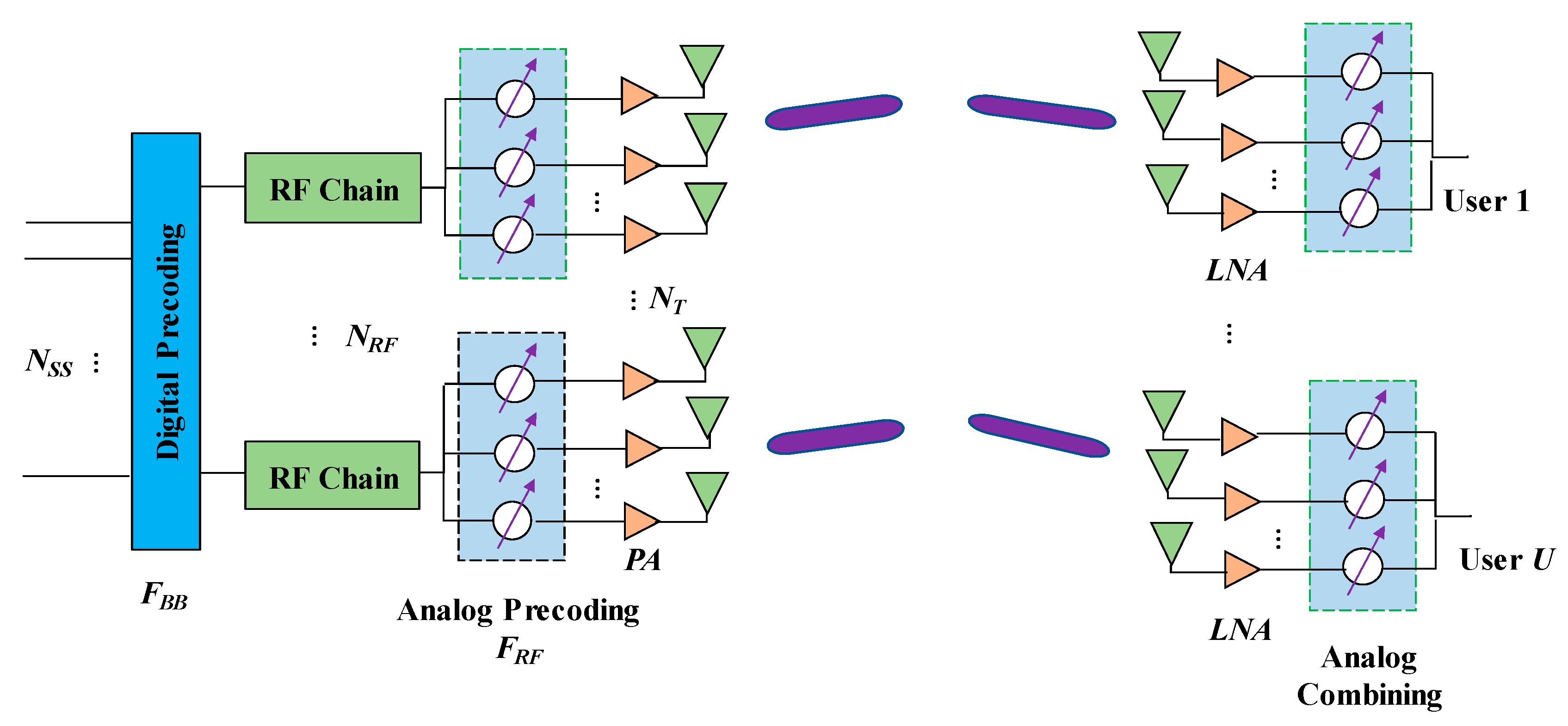
2.1. Transceiver Architecture

In a multi-user millimeter wave system using split sub-array-type MIMO hybrid modulus precoding architecture, considering the small wavelength of millimeter waves, the integration of a large antenna array with a small form factor can be achieved; on the other hand, for simple users, in terms of equipment, the processing complexity of combining and receiving with hybrid modulus is high. Thus, the user equipment can only use analog combined reception to take advantage of the increased gain of large antenna arrays and reduce the processing complexity of simple user equipment. Figure 1 shows the architecture of a millimeter wave system for multi-user split sub-array-type MIMO hybrid modulus precoding for analog combined reception.
y k = w k H H k F R F F B B x + w k H n k
where w k denotes the N R × 1 dimensional reception combining vector of the k th user, H k denotes the N R × N T dimensional channel matrix of the user k , F R F denotes an analog precoding matrix of N T × N R F dimension, and F B B denotes digital precoding of N R F × U dimension, and F B B = [ f B B , 1 , f B B , 2 , ,   f B B , U ] , where f B B , k represent the N R F × 1 digital precoding vector corresponding to the data stream of user k , x = [ x 1 , x 2 , , x U ] T represents the data vector sent to users and E [ x x H ] = I U ;   n k represents the noise vector received by the user k obeying the complex Gaussian distribution C N ( 0 , σ n 2 I N R ) . ( · ) H , ( · ) T indicates the conjugate transposition and transposition, E [ · ] means taking the expectation.
Digital precoding can change the amplitude and phase of the signal, while analog precoding, which is limited by the constant modulus, only adjusts the phase of the signal. The analog precoding on the N R F sub-array of the base station is implemented by a constant mode phase shifter, and the F R F can be expressed as
F R F = [ f 1 0 0 0   0 f 2 0 0     0 0 f N R F ]
where f i   ( i = 1 , 2 , ,   N R F ) denotes the N a r r × 1 analog precoding vector corresponding to the i th sub-array, and the amplitude of each element of f i is always 1 N a r r . In Equation (1), the amplitude of each element of the analog combining vector w k on the user is always 1 N R . In this paper, the total transmission power of the transmitting end is normalized by limiting F R F F B B F 2 = 1 , where · F indicates the Frobenius norm.

2.2. Channel Model

Compared with the low-band channel with the rich scattered environment, the channel propagation loss in the millimeter wave band is severe, the scattering environment is poor, and the number of effective scatterers is limited [24,25,26,27]. In order to show the sparse scattering characteristics of millimeter wave channels, a parametric channel model with finite scatterers is used in this paper. Assuming that the number of scatterers of user k is S k , its channel matrix H k can be expressed as [28,29].
H k = N T N R S k A R x , k ( θ ) G k A T x , k H ( ϕ )
where A R x , k ( θ ) represents the receive array response matrix, A T x , k H ( ϕ ) denotes the transmit array response matrix, and G k represents the path gain, which is given by [27] G k = [ g 1 g 2 g S k ] ,   g i = ( i = 1 , ,   S k ) . It may be assumed that there is only one effective propagation path in the cluster formed by each scatterer, and the gain of the broadcast path is an independent and identically distributed complex Gaussian random variable obeying the zero mean unit variance.
The receive array response A R x , k ( θ ) = [ a r x ( θ 1 ) , , a r x ( θ S k )   ] , the transmit array response matrix A T x , k H ( ϕ ) = [ a t x ( ϕ 1 ) , , a t x ( ϕ S k )   ] , where θ i , ϕ i represents the angle of arrival (AoA) and the angle of departure (AoD) of the i th path, respectively. The array response vectors a r x ( θ i ) and a t x ( ϕ i ) differ according to the antenna type [30]. Commonly, there are uniform planar arrays (UPAs) and uniform linear arrays (ULA). In the simulation of this paper, ULA is used, and the receiving array response vector a r x ( θ i ) can be expressed as:
a r x ( θ i ) = 1 N R   [ 1 ,   e j 2 π λ   d sin ( θ i ) ,   e j 2 π λ   2 d sin ( θ i ) , e j 2 π λ   ( N R 1 ) d sin ( θ i )   ] T
where λ represents the wavelength and d represents the spacing of the sub-array antenna elements. In the split-distributed array MIMO architecture, the sub-arrays of the base station (BS) are separated from each other; the sub-array spacing should be chosen such that adjacent sub-arrays have a lower correlation or are irrelevant. Thereby, the interference between adjacent sub-array beams is reduced when the base station respectively aligns each sub-array beam with different users [30].
Therefore, the transmit array response vector a t x ( ϕ i ) can be expressed as [6,7,8,9]:
a t x ( ϕ i ) =   1 N T [ 1 ,   e j 2 π λ   ( N a r r 1 ) d sin ( ϕ i ) ,   e j 2 π λ   ( D T x + ( N a r r 1 ) d ) sin ( ϕ i ) , e j 2 π λ   ( ( N R F 1 ) D T x + N R F ( N a r r 1 ) d ) sin ( ϕ i )   ] T
where D T x represents the minimum distance between adjacent sub-array antenna elements of the base station, and the selection of D T x should be such that adjacent sub-arrays of the base station are separated from each other.

3. Proposed Algorithm

For the multi-user millimeter wave MIMO system transceiver framework shown in Figure 1, it is known from Equation (1) that the rate R k of the user k can be expressed as
R k = log 2 ( | 1 + w k H H k F R F f B B , k f B B , k H F R F H H k H w k w k H ( i = 1 , i k N R F H k F R F f B B , i f B B , i H F R F H H k H + σ n 2 I N R ) w k | )
where | · | represents an absolute value, and log 2 ( · ) represents a logarithm of base 2. The problem of designing hybrid modulus precoding with the aim of system and rate maximization is expressed as
{ arg max F R F , F B B , w k k = 1 U log 2 ( | 1 + w k H H k F R F f B B , k f B B , k H F R F H H k H w k w k H ( i = 1 , i k N R F H k F R F f B B , i f B B , i H F R F H H k H + σ n 2 I N R ) w k | ) s . t .   F R F F B B F 2 = 1   | f k ( m ) | = 1 N a r r ,   m = 1 , 2 , ,   N a r r   | w k ( n ) | = 1 N R ,   n = 1 , 2 , ,   N R  
Equation (7) is a ternary joint optimization problem for F B B , F R F , and w k . The constant model property of the sub-array precoding vector makes the direct optimal solution of the problem more difficult to obtain. In this paper, Equation (7) is divided into two parts, analog and digital, to determine the design part of the analog part.
In a split MIMO hybrid analog precoding architecture, the analog portion can be designed to adjust the transmit beam of each sub-array to produce a directional beam that is aligned with the user, and the digital portion can be designed to eliminate interference between multiple user data streams. In order to solve the analog part, the base station sub-array is first paired with the user, in turn; that is, the base station k th sub-array transmits data to the k th user, and f k and w k are designed such that the propagation path of the base station sub-array to the corresponding paired user is approximated as line-of-sight (LoS) propagation in the beam domain. Further, this can be achieved by maximizing the received signal-to-interference-and-noise ratio (SINR) of user k . When digital precoding is not considered, the received SINR of user k is expressed as
S I N R k = w k H H k k f k f k H H k k H w k w k H ( i = 1 , i k N R F H k i f i f i H H k i H + σ n 2 I N R ) w k
where H k i represents the channel matrix between user k and the i t h BS sub-array. The problem of solving the analog part of the hybrid modulus precoding is expressed as
arg m a x w k , f k { w k H H k k f k f k H H k k H w k w k H ( i = 1 , i k N R F H k i f i f i H H k i H + σ n 2 I N R ) w k }
When the analog precoding matrix F R F is known, the straight solution of w k in Equation (9) is
w k = ( i = 1 , i k N R F H k i f i f i H H k i H + σ n 2 I N R ) 1 H k k f k ( i = 1 , i k N R F H k i f i f i H H k i H + σ n 2 I N R ) 1 H k k f k 2
where ( · ) 1 represents the inverse of the matrix. The w k given by Equation (10) is not constant modulus and does not satisfy the constant modulus limitation of w k in problem (7). The analog combining vector satisfying the constant modulus limit is represented by w ˜ k and it is solved with the goal of minimizing w ˜ k w k 2 2 . It is obtained by w ˜ k H w ˜ k = 1 and w k H w k = 1 as
w ˜ k w k 2 2 = ( w ˜ k w k ) H ( w ˜ k w k ) = 2 ( 1 R e ( w k H w ˜ k ) )
where R e ( · ) represents the real part. When w ˜ k = 1 N R   e j   ( w k ) and R e ( w k H w ˜ k ) takes the maximum value, w ˜ k w k 2 2 is the smallest. Therefore, Equation (10) satisfies the constant module limits as
w k = 1 N R   e j   ( ( i = 1 , i k N R F H k i f i f i H H k i H + σ n 2 I N R ) 1 H k k f k )
Considering that the channel of the time division synchronization system has reciprocity, H k i is used to indicate the channel matrix in the uplink; that is, the uplink channel matrix between the k t h sub-array of the base station and the user i , and then H k i = H i k H . In the uplink, f k is used to represent the analog precoding vector of the k t h user, f k = w k , and the analog combining vector w k is obtained by maximizing the received SINR of each sub-array of the base station as
w k = 1 N a r r   e j   ( ( i = 1 , i k U H k i f i f i H H k i H + σ n 2 I N a r r ) 1 H k k f k )
The downlink analog precoding vector f k = w k . In summary, the analog constant modulus precoding algorithm based on channel reciprocity (APoCR) is summarized in Algorithm 1. After determining the analog precoding vector and the user combining vector of the base station sub-array, the base station digital precoding matrix is designed to eliminate interference between multiple user data streams. When designing digital precoding, the base station is usually required to know the channel state information (CSI), and the base station can obtain the RF equivalent channel information by channel feedback through user feedback or channel reciprocity based on the time division multiplexing (TDM) system [26]. Using H ˜ R F = [ H ˜ 1 T , H ˜ 2 T , , H ˜ U T ] represents the RF equivalent channel matrix of the U × N R F dimension, where H ˜ k represents the RF equivalent channel of user k , H ˜ k = w k H H k F R F ( k = 1 , 2 , , U ) . After the base station obtains the RF equivalent channel matrix, the baseband digital precoding matrix F B B is designed by using a block diagonalization (BD) algorithm to eliminate interference between multiple user data streams.
Algorithm 1 APoCR Algorithm
Symmetry 11 00786 i001

4. Numerical Simulation Analysis

In this section, under the split MIMO hybrid modulus precoding framework shown in Figure 1, the proposed APoCS algorithm is simulated and compared with existing algorithms. The simulation parameters are shown in Table 1. Assume that the AoA and AoD of the propagation path obey [ 0 , 2 π ] evenly distributed. The signal-to-noise ratio (SNR) is defined as S N R = 10   log ( P T σ n 2 ) d B , where P T represents the total transmit power. All simulation results were obtained by averaging 5000 channels.

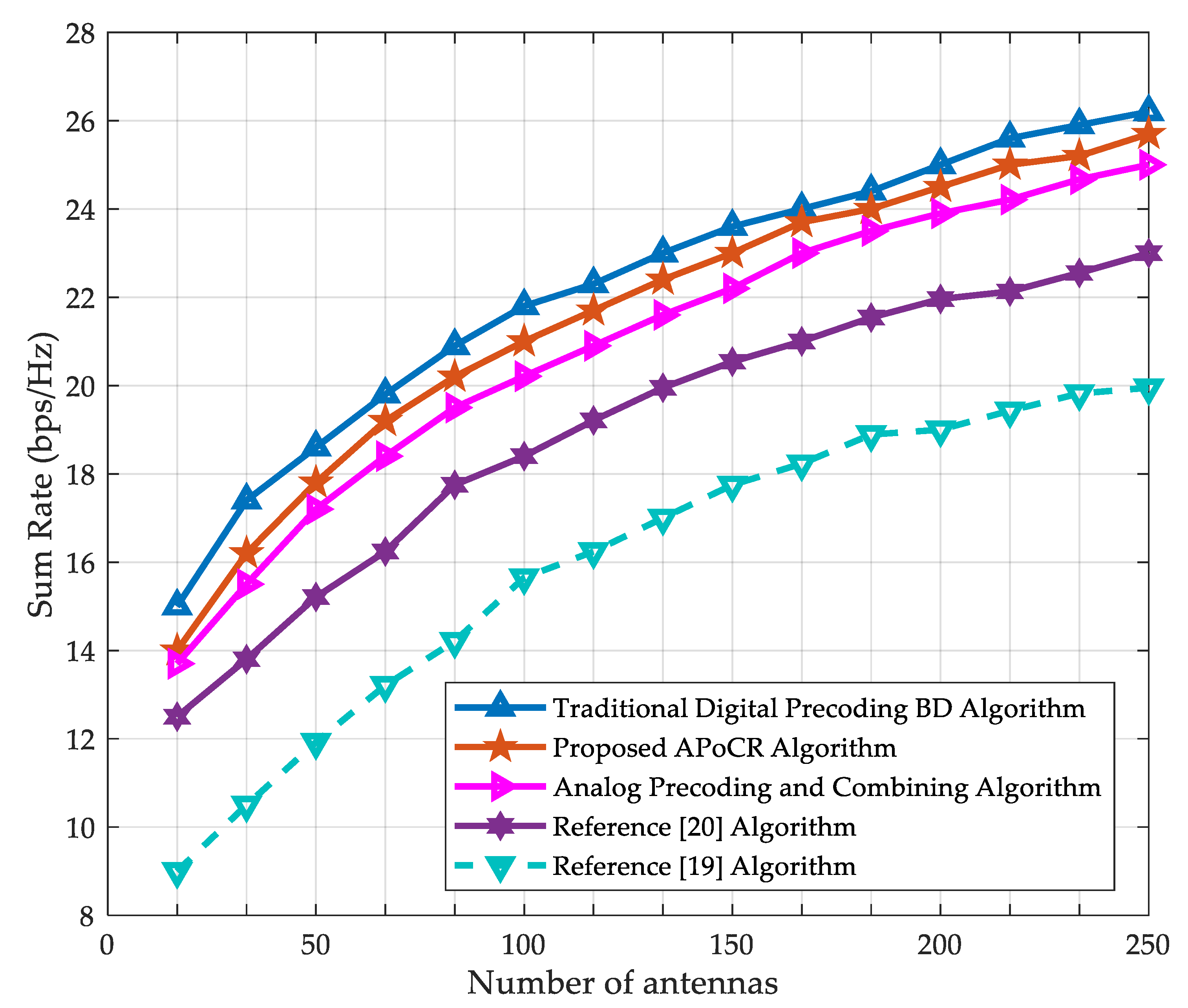
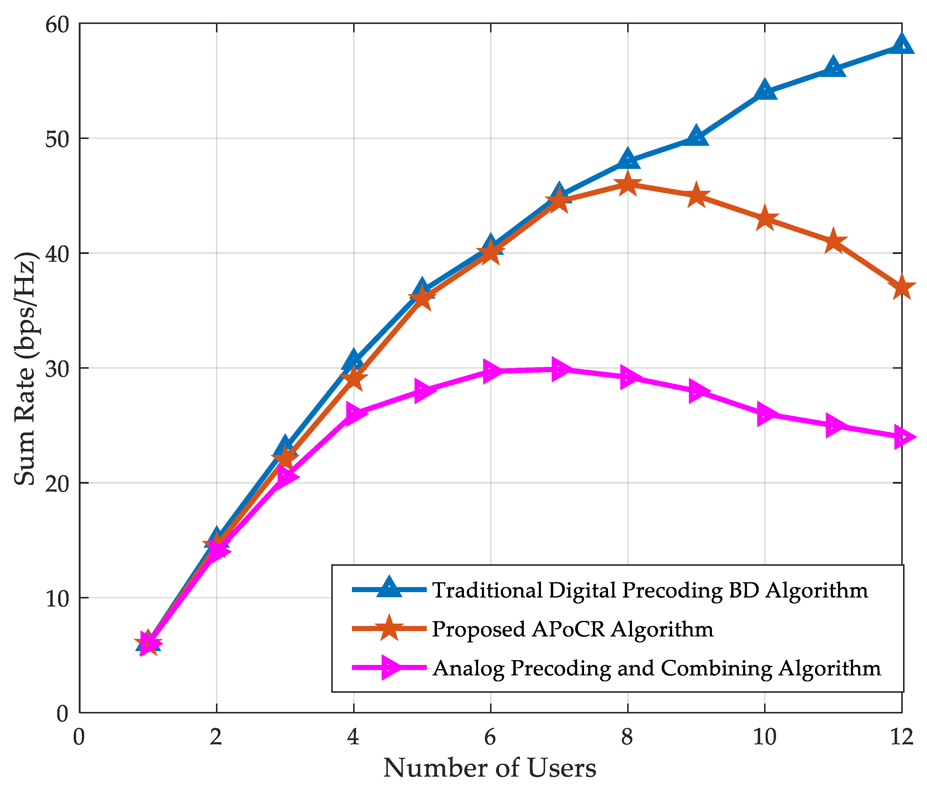
4.1. Comparison Plan

In order to verify the effectiveness of the proposed algorithm, this section uses the hybrid modulus precoding algorithm in the split sub-array architecture and compared it with the the existing literature Schemes (1)–(4).
The comparison schemes adopted are:
(1)
The traditional pure digital precoding BD algorithm; the number of RF links of the base station is equal to its number of transmitting antennas;
(2)
The hybrid precoding algorithm based on continuous interference cancellation proposed in [19];
(3)
In the single-user scenario described in [20], the codebook-based transceiver terminal array random matching algorithm;
(4)
Analog precoding and combining, regardless of eliminating inter-user interference (IUI) in the digital domain.
Since Scheme 2 [19] is mainly for a single-user scenario, and the transmission data stream to the transmission sub-array is an independent path, the adjacent paths are independent, which is slightly different from the architecture mentioned in this paper. When simulating, it is extended to the multi-user scenario shown in Figure 1, and the digital part is solved using the BD algorithm. At the same time, Scheme 3 [20] is also extended to the multi-user scenario, and the digital part uses the BD algorithm. In Scheme 3, the codewords of the base station sub-array and the user sub-array are selected with the aim of maximizing the system and rate without considering the digital part. The number of training required to select the codewords of the first pair of matching base stations and the user sub-array is N R F U B T B R ; B T and B R respectively represent the number of codewords selected by the base station and the user sub-array. After determining the first matching pair, the number of training required for the second pair of matching base stations and user sub-array codewords is ( N R F 1 ) ( U 1 ) B T B R ; and so on to all matches. When N R F = U , the total number of training required is N R F   ( N R F + 1 )   ( 2 N R F + 1 ) 6 B T B R . In this simulation, both the base station and the user sub-array use the Discrete Fourier Transform (DFT) code with the number of codewords as N B , which can be expressed as
c ( m , n ) = 1 N a r r   e j   ( 2 π ( m 1 ) ( n 1 ) N B ) ,   m = 1 , 2 , ,   N a r r ,   n = 1 , 2 , ,   N B
In addition, the base station and the sub-array of the user randomly select the codewords each time. In the two implementations under the same conditions, the users corresponding to the same base station sub-array may be different. Scheme 4 (analog precoding and combining) is the performance achieved by the algorithm in the case where the base station does not perform digital precoding to eliminate inter-user interference.

4.2. Algorithm Simulation Analysis

Figure 2 shows the system and rate curves for two different users, the base station antenna number N T = 32 , the number of sub-array antennas N a r r = 16 , and the number of user antennas N R = 16 . It can be seen that the traditional pure digital precoding BD algorithm has the largest system and rate, but this is in exchange for the high hardware cost of the number of RF links equal to the base station transmit antenna. For the same system and rate values, the algorithm proposed in [20] reduces the required signal-to-noise ratio by approximately 2.5 dB when the number of codewords N B = 16 is lower than N B = 8 , but the number of training required to select the codeword is four times when N B = 8 . Under the same signal-to-noise ratio, the proposed algorithm has a system and rate difference of less than 1bps/Hz when compared with the traditional pure digital precoding BD algorithm at N R F = 2 . This difference is caused by the analog precoding and analog combining vectors. Inherent loss is due to constant mode limitation, system and rate ratio N B . The algorithm proposed in [20] is higher than 2 bps/Hz, which is 4 bps/Hz higher than N B = 8 , which is also superior to the hybrid modulus precoding algorithm based on continuous interference cancellation proposed in [19]. In addition, analog precoding and the combination achieved by the proposed algorithm are combined at a low SNR, and the rate is close to the performance of the hybrid modulus precoding, but as the signal-to-noise ratio increases, the inter-user interference increases, and the rate is lower than the hybrid modulus precoding algorithm proposed in this paper.
Figure 3 shows the variation of the system rate of the different algorithms with the number of antennas for two users with a signal-to-noise ratio of 0 dB and the number of codewords used in [20] is equal to the number of sub-array antennas. It can be seen that with the increase in the number of antennas, the proposed algorithm is still very close to the sum rate curve of the traditional digital precoding BD algorithm, and is superior to the algorithms proposed in [19,20].
Figure 4 shows the variation of the system and rate with the number of users with a signal-to-noise ratio of 0 dB and a sub-array antenna number of N a r r = 16 . The simulation shows that with the increase in the number of users, the proposed algorithm can still obtain the performance of the nearly optimal pure digital precoding algorithm. However, when the number of users is greater than 9, the difference between the proposed algorithm and the optimal pure digital precoding algorithm increases, which is caused by the increase in interference sources between users. The curve changes corresponding to the analog precoding and combining also illustrate the effect of interference and rate between users. Therefore, the proposed algorithm is more suitable for cases where the number of users is not too high, such as a wireless LAN transmission environment. The wireless LAN standard IEEE802.11ac supports up to four users to communicate at the same time, and the proposed algorithm can support eight users at the same time.
Figure 5 shows the SINR of each user at a signal-to-noise ratio of 0 dB and the sub-array antenna number N a r r = 16 . The user signal-to-noise ratio of Equation (8) varies with the number of iterations. Figure 5a shows the SINR for two users and Figure 5b shows the SINR for four users. It can be seen that after five iterations, the SINRs of the two users all converge. When the number of iterations is 20, the SINRs of all four users converge. Because the number of interferences per user increases with the increase in users, the number of iterations required for the proposed algorithm to converge will increase, but the proposed algorithm converges faster than the number of trainings in [20].

5. Conclusions

In this paper, a hybrid analog–digital precoding architecture of multi-user millimeter wave MIMO systems was studied. The analog-receiving scheme under the MIMO architecture of split sub-array was proposed for the first time. Considering that solving the hybrid modulus precoding with the goal of maximizing system and rate is a ternary joint optimization problem, and the constant modulus limitation of the simulation part makes the optimal solution difficult to obtain, it was divided into two parts: analog and digital. Furthermore, by pairing the base station sub-array with the users, one by one, a hybrid modulus precoding algorithm based on channel reciprocity was proposed. The algorithm respectively solves the analog combining vector and the analog precoding vector by maximizing the received SNR of each downlink user and each sub-array of the uplink. After fixing the analog part of the system, the multi-user block diagonalization (BD) algorithm was used to design the base station digital precoding matrix to eliminate interference between multiple user data streams. Finally, the proposed algorithm and the traditional pure digital precoding BD algorithm and the existing algorithms were numerically simulated and compared. The simulation results show that the proposed algorithm has fast convergence speed and can obtain near-optimal pure digital pre-preparation. The performance of the encoding, as well as the system rate, is superior to existing literature algorithms.

Author Contributions

Conceptualization, I.K. and M.H.A.; Data curation, M.H.Z. and I.K.; Formal analysis, M.A., I.K., M.O.A. and Y.H.; Funding acquisition, M.H.A., J.K., J.H.K.; Investigation, I.K., M.H.A.; Methodology, M.H.Z., I.K., M.A. Project administration, M.A. and I.K.; Software, M.H.Z., I.K.; Writing—original draft, M.A., I.K. and Y.H.; Writing—review and editing, I.K., M.H.Z. and, J.K., M.O.A, and M.H.A.

Funding

This work was supported by the Human Resources Development of the Korea Institute of Energy Technology Evaluation and Planning (KETEP) grant funded by the Korea government Ministry of Trade, Industry and Energy (No. 20164030201340).

Acknowledgments

The authors thank anonymous reviewers for their careful corrections to and valuable comments on the original version of this paper.

Conflicts of Interest

The authors declare no conflict of interest.

References

  1. Semiari, O.; Saad, W.; Bennis, M.; Debbah, M. Integrated millimeter-wave and Sub-6 GHz wireless networks: A roadmap for joint mobile broadband and ultra-reliable low-latency communications. IEEE Wirel. Commun. 2019, 26, 109–115. [Google Scholar] [CrossRef]
  2. Shi, J.; Lv, L.; Ni, Q.; Pervaiz, H.; Paoloni, C. Modeling and analysis of point-to-multipoint millimeter wave backhaul networks. IEEE Trans. Wirel. Commun. 2019, 18, 268–285. [Google Scholar] [CrossRef]
  3. Wang, T.; Li, G.; Ding, J.; Miao, Q.; Li, J.; Wang, Y. 5G Spectrum: Is China ready? IEEE Commun. Mag. 2015, 53, 58–65. [Google Scholar] [CrossRef]
  4. Saraereh, O.A.; Khan, I.; Alsafasfeh, Q.; Alemaishat, S.; Kim, S. Low-Complexity Channel Estimation in 5G Massive MIMO-OFDM Systems. Symmetry 2019, 11, 713. [Google Scholar] [CrossRef]
  5. Elkhashlan, M.; Duong, T.Q.; Chen, H.H. Millimeter-wave communications for 5G-Part 2: Applications. IEEE Commun. Mag. 2015, 53, 166–167. [Google Scholar] [CrossRef]
  6. Yu, H.; Yang, G.; Meng, F.; Li, Y. Performance analysis of MIMO system with single RF Link based on switched parasitic antenna. Symmetry 2017, 9, 304. [Google Scholar] [CrossRef]
  7. Al-Sharif, M.H.; Kelechi, A.H.; Kim, J.; Kim, J.H. Energy efficiency and coverage trade-off in 5G for eco-friendly and sustainable cellular networks. Symmetry 2019, 11, 408. [Google Scholar] [CrossRef]
  8. Yu, H.; Yang, G.; Li, Y.; Meng, F. Design and analysis of multiple-input multiple-output radar system based on RF single-link technology. Symmetry 2018, 10, 130. [Google Scholar] [CrossRef]
  9. Deong, L.; Zhao, H.; Chen, Y.; Chen, D.; Wang, T.; Lu, L.; Zhang, B.; Hu, L.; Gu, L.; Li, B.; et al. Introduction on IMT-2020 5G Trials in China. IEEE J. Sel. Areas Commun. 2017, 35, 1849–1866. [Google Scholar] [CrossRef]
  10. IEEE Std 802.15.3c-2009. Wireless MEDIUM ACCESS CONTROL (MAC) and Physical Layer (PHY) Specifications for High Rate Wireless Personal Area Networks (WPANs); IEEE Standards Association Press: Piscataway, NJ, USA, 2009; Volume 49, pp. 114–121. [Google Scholar]
  11. IEEE P802.11ad. Wireless LAN Medium Access Control (MAC) and Physical Layer (PHY) Specifications-Amendment 3: Enhancements for Very High Throughput in the 60 GHz Band; IEEE Standards Association Press: Piscataway, NJ, USA, 2012; Volume 21, pp. 1–24. [Google Scholar]
  12. Rappaport, T.S.; Xing, Y.; MacCartney, G.R.; Molisch, A.F.; Mellios, E.; Zhang, J. Overview of millimeter wave communications for fifth-generation (5G) wireless networks-with a focus on propagation models. IEEE Trans. Antennas Propag. 2017, 65, 6213–6230. [Google Scholar] [CrossRef]
  13. Zhou, P.; Cheng, K.; Han, X.; Fang, X.; Fang, Y.; He, R.; Long, Y.; Liu, Y. IEEE 802.11ay-based mmwave wlans: Design challenges and solutions. IEEE Commun. Surv. Tutor. 2018, 20, 1654–1681. [Google Scholar] [CrossRef]
  14. Wang, J.; Lan, Z.; Pyo, C.W.; Baykas, T.; Sum, C.S.; Rahman, M.A.; Kato, S. Beam codebook-based beamforming protocol for multi-Gbps millimeter-wave WPAN systems. IEEE J. Sel. Areas Commun. 2009, 27, 1390–1399. [Google Scholar] [CrossRef]
  15. Alkhateeb, A.; Ayach, O.E.; Leus, G.; Heath, R.W. Channel estimation and hybrid precoding for millimeter wave cellular systems. IEEE J. Sel. Top. Signal Process. 2014, 8, 831–846. [Google Scholar] [CrossRef]
  16. Ayach, O.E.; Rajagopal, S.; Surra, S.A.; Pi, Z.; Heath, R.W. Spatially sparse precoding in millimeter-wave MIMO systems. IEEE Trans. Wirel. Commun. 2013, 13, 1499–1513. [Google Scholar] [CrossRef]
  17. Han, S.; Lin, I.C.; Xu, Z.; Rowell, C. Large-scale antenna systems with hybrid analog and digital beamforming for millimeter wave 5G. IEEE Commun. Mag. 2015, 53, 186–194. [Google Scholar] [CrossRef]
  18. Alkhateeb, A.; Leus, G.; Heath, R. Limited feedback hybrid precoding for multi-user millimeter wave systems. IEEE Trans. Wirel. Commun. 2015, 14, 6411–6494. [Google Scholar] [CrossRef]
  19. Li, N.; Wei, Z.; Geng, J.; Sang, L.; Yang, D. Multiuser hybrid beamforming for max-min SINR problem under 60 GHz wireless channel. In Proceedings of the IEEE 24th Annual International Symposium on Personal, Indoor, and Mobile Radio Communication (PIMRC), Washington, DC, USA,, 2–5 September 2014; pp. 123–128. [Google Scholar]
  20. Kim, M.G.; Lee, Y. MSE-based Hybrid RF/Baseband processing for millimeter wave communication systems in mimo interference channels. IEEE Trans. Veh. Technol. 2015, 64, 2714–2720. [Google Scholar] [CrossRef]
  21. Agiwal, M.; Roy, A.; Saxena, N. Next generation 5G wireless networks: A comprehensive survey. IEEE Commun. Surv. Tutor. 2016, 18, 1617–1655. [Google Scholar] [CrossRef]
  22. Gao, X.; Dai, L.; Han, S.; Chih-Lin, I.; Heath, R.W. Energy-efficient hybrid analog and digital precoding for mmwave MIMO systems with large antenna arrays. IEEE J. Sel. Areas Commun. 2016, 34, 998–1009. [Google Scholar] [CrossRef]
  23. Capar, C.; Hang, S.; Hui, D. Efficient Beam Selection for Hybrid Beamforming; IEEE 802.11-15/1131r0; IEEE Standards Association Press: Piscataway, NJ, USA, 2015; Volume 11, pp. 1–15. [Google Scholar]
  24. Heath, R.W.; Alkhateeb, A.; Mo, J. Millimeter wave MIMO precoding/combining: Challenges and potential solutions. IEEE Commun. Mag. 2014, 52, 122–131. [Google Scholar]
  25. Chang, S.H.; Taori, R.; Kim, T.Y. A view on IEEE 802.11ay. IEEE 802.11-15/0636r0; IEEE Standards Association Press: Piscataway, NJ, USA, 2015; Volume 15, pp. 1–11. [Google Scholar]
  26. Rappaport, T.S.; Sun, S.; Zhao, H.; Azar, Y.; Wang, K.; Gutierrez, F.; Mayzus, R. Millimeter wave mobile communications for 5G cellular: It will work! IEEE Access 2013, 1, 335–349. [Google Scholar] [CrossRef]
  27. Sulyman, A.I.; Nassar, A.M.T.; Samimi, M.K.; MacCartney, G.R.; Rappaport, T.S.; Alsanie, A. Radio propagation path loss models for 5G cellular networks in the 28 GHz millimeter-wave bands. IEEE Commun. Mag. 2014, 52, 78–86. [Google Scholar] [CrossRef]
  28. Forezna, A.; Love, D.J.; Heath, R.W. Simplified spatial correlation models for clustered MIMO channels with different array configurations. IEEE Trans. Veh. Technol. 2007, 56, 1924–1934. [Google Scholar]
  29. Perahia, E.; Stacey, R. Next Generation Wireless LANs; Cambridge University Press: Cambridge, UK, 2013; pp. 321–334. [Google Scholar]
  30. Guo, Y.; Li, L.; Wen, X.; Chen, W.; Han, Z. Sub-array based hybrid precoding design for downlink millimeter-wave multi-user massive MIMO systems. In Proceedings of the IEEE International Conference on Wireless Communications and Signal Processing (WCSP), Nanjing, China, 11–13 October 2017; pp. 1–4. [Google Scholar]
Figure 1. Proposed hybrid analog–digital precoding multi-user millimeter wave (MU-mmWave) Multiple-Input Multiple-Output (MIMO) with split sub-array and analog combining at receiver.
Symmetry 11 00786 g001
Figure 2. Comparison of the sum rate of the proposed analog constant modulus precoding algorithm based on channel reciprocity (APoCR) with other state-of-the-art algorithms under different SNR levels with U = 2 ,   N a r r = N R = 16 .
Symmetry 11 00786 g002
Figure 3. Comparison of the sum rate of the proposed APoCR algorithm with other state-of-the-art algorithms under different a number of antennas with U = 2 .
Symmetry 11 00786 g003
Figure 4. Comparison of the sum rate of the proposed APoCR algorithm with other state-of-the-art algorithms under a different number of users with N a r r = 16 ,   S N R = 0   d B .
Symmetry 11 00786 g004
Figure 5. Comparison of the signal-to-interference-and-noise ratio (SINR) of different numbers of users under various numbers of iterations with N a r r = 16 ,   S N R = 0   d B . (a) U = 2 ; (b) U = 4 .
Symmetry 11 00786 g005
Table 1. Simulation parameters.
ParameterValue
Frequency band45 GHz
Wavelength λ6.7 mm
Channel modelParametric with finite scatterers
Number of scatterers Sk12
Sub-array antenna cell spacing d0.5 λ
Adjacent sub-array spacing DTxλ

