Abstract
Geomagnetic fingerprint has been actively studied because of the high signal stability and positioning resolution even when the time has elapsed. However, since the measured three-axis geomagnetism signals at one position are irregular according to the change of the azimuth angle, a large-sized database which is stored magnitudes per angles is required for robust and accurate positioning against the change of the azimuth angle. To solve this problem, this paper proposes a novel approach, an elliptic coefficient map based geomagnetic fingerprint. Unlike the general fingerprint, which stores strength or magnitude of the geomagnetism signals depending on the position, the proposed algorithm minimized the size of databased by storing the Ellipse coefficient map through the ellipse equation derived from the characteristics of 2-D magnetic vectors depending on the position. In addition, the curvature bias of ellipse was reduced by applying the normalized linear least-squares method to 2-D geomagnetic characteristics and the positioning accuracy was improved by applying the weighted geomagnetic signal equalization method.
1. Introduction
Fingerprint is a representative indoor positioning method that uses the difference of measured signal strength such as Wi-Fi [1], BLE (Bluetooth low energy) [2], geomagnetic [3,4,5] according to the location. The fingerprint is divided into a training phase that store the signals according to the position of the regular interval, called Reference point (RP), and a positioning phase that compares the measured signal with the stored position in real-time. Therefore, it is essential that a database is required but it is advantageous to apply to the complex indoor space because it is robust against NLOS (non-line of sight) environment compared with TOA (time of arrival) using round trip time of radio. In particular, the geomagnetic fingerprint does not need to install separate APs (access points) in the indoor space unlike Wi-Fi, Zigbee, BLE, etc. Therefore, the Fingerprint system construction and maintenance cost are low since there are no positioning errors in accordance with change location and power of APs [6,7,8]. WiFi-based positioning is not affected by azimuth angle, but many geomagnetic signals require a database because the signal varies according to the azimuth angle. In addition, it is very difficult to estimate the initial start position without fixed AP.
Recently, geomagnetic fingerprint studies have improved the positioning accuracy by constructing systems that are integrated with indoor positioning technology, such as Wi-Fi and corrects the position estimation error through filtering algorithms, such as Kalman and particle filters. Most systems are based on the total intensity of the geomagnetism signal along the 3-axes. However, geomagnetism signals change according to changes in the azimuth, large positioning errors may occur, even from the same position [9,10,11].
Nguyen et al. [9] proposed an algorithm that improves the positioning accuracy of the Wi-Fi fingerprint by integrating geomagnetism. This algorithm uses geomagnetism as an assistive technology at the landmark location for indoor positioning based on Wi-Fi. This method improves positioning accuracy compared to the existing Wi-Fi fingerprint algorithm. However, an error may occur because the values of the total intensity of the geomagnetism signals stored for each reference point (RP) located at regular intervals do not consider azimuth angles.
Chung et al. [10] proposed an indoor positioning algorithm based on fingerprints that consider the change of geomagnetism signals according to azimuth angles. In the training phase, by using stepping motors, the values of the total intensity of the geomagnetism at all azimuth angles were constructed in the database. In the positioning phase, the geomagnetism signals collected from the four sensors facing 0, 90, 180, and 270° were compared with the signals from the database. The location at which the difference in root mean square (RMS) was minimal and recognized as the position. Thus, it reflects the change of geomagnetism signals according to the azimuth angles; however, it takes a long time to build the database and requires at least four sensors.
Xie et al. [11] proposed the magnetic fingerprinting based indoor localization (MaLoc) algorithm, which uses smartphones to acquire ambient magnetic measurements. The system consists of a client running on a smartphone and a server implementing a new reliability enhancement particle filter. MaLoc does not require prior calibration owing to its self-calibration feature and does not apply any restrictions on smartphone orientation. However, an error occurs in the position estimation using the geomagnetism of the unmapped azimuth angles.
As described above, for the geomagnetic fingerprint, it is difficult to recognize the position of the signal at an angle that is not stored in a database. In addition, there is a limit to store the signal for all azimuth angles in indoor space. To solve these problems, in this paper, we propose an ellipse coefficient map (ECM)-based using Fingerprint based on the ellipse equation (UFEE) that integrates 2-D magnetic vectors and yaw-axis correction techniques to reduce the positioning error caused by the azimuthal change in an indoor environment using only a single geomagnetic sensor and a limited database. To verify the validity of the proposed algorithm, the UFEE results were compared with existing geomagnetism intensity-based results.
2. Related Works
2.1. Signal Characteristics of 3-Axis Geomagnetism
The magnetic vector of the earth consists of seven components as shown in Figure 1. X is the geographical north (true north) at the north end of the earth’s rotation axis, Y is the geographical west, and Z is the vertical component of the geomagnetic field toward the earth’s nadir. F is the earth’s magnetic force, H is the horizontal magnetic force (magnetic north), D is the angle (declination) between true north and magnetic north, respectively [12]. The total magnitude of the geomagnetism output in the three axes is given by Equation (1) and the magnitude of the horizontal geomagnetic field is given by Equation (2).
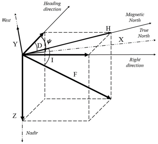
Figure 1.
Seven components of the magnetic vector.
Here, , are a heading direction, a right direction, and a nadir direction, respectively. To find the azimuth angle on the body coordinate system, it is essential to transform the horizontal coordinate system according to the current attitude angle, as shown in the following Equation (3).
where and are the roll angle and the pitch angle. , , and are three-axis earth magnetic fields measured in the fuselage coordinate system, and , , and are magnetic vectors in which the attitude angle is compensated. Hence, the horizontal magnetic vectors and can be obtained and the azimuth angle can be obtained as in Equation (4) [13].
This azimuth is a very important factor in the prediction of the movement and the ideal geomagnetic vector according to the azimuth angle at one location is expressed in the form of a perfect circle as shown in Figure 2. However, due to the inherent errors (soft-iron effect) of the geomagnetic sensor and the measurement errors (hard-iron effect) by the reinforced structure and the magnetic objects, the shapes of the geomagnetic vector according to the angle appears in various elliptical shapes and its size is not constant either [14]. Therefore, a conventional Fingerprint that compares the magnitude of geomagnetic vectors at each position is caused a serious positioning error only by a simple azimuth angle change on one position. To solve this problem, many geomagnetic vectors data are saved in the database according to the angle, or a variety of communications and sensors are added.
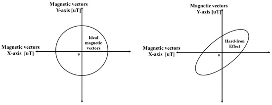
Figure 2.
2-D characteristic of magnetic vectors for all azimuth angles.
2.2. Wi-Fi and Geomagnetic Fingerprint
For the indoor positioning method using acceleration, a Wi-Fi and a geomagnetic sensor built in a smartphone have been studied. In the case of an acceleration sensor, the application skill is simple, but it is necessary to specify the starting position and it is difficult to track for a long time due to the cumulative errors. On the other hand, Fingerprint using Wi-Fi or geomagnetism signals can solve this problem because it saves per-location characteristics using DB. Figure 3 shows a flow chart of the Wi-Fi Fingerprint. The Fingerprint is divided into training and positioning phase.
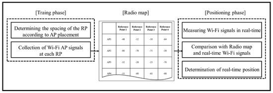
Figure 3.
Flow chart of Wi-Fi Fingerprint.
In the training phase, a user measures the signal strength that can be located at a regular interval of RP and generates these as a database called a radio map. The optimum RP interval is determined according to the kind of the signal applied to the fingerprint and the indoor environment. This interval means resolution in which the fingerprint system can distinguish each position. Therefore, the narrower the interval, the better the positional accuracy. However, since the standard deviation of RSSI measured at one RP is large, RP is applied at intervals of 2 to 3 m, which is the smallest unit that can distinguish positions. The RSSIs measured for each RP have a unique strength depending on the relative distance between the APs and the RPs and the existence of obstacles, and these strengths are stored in the DB.
In the positioning phase, based on the stored DB, the user who has a smartphone moves to real time and compares the measured RSSIs with DB to estimate the user’s position to the location of the most similar RP. For real-time processing, deterministic or probabilistic models [15,16] with low computational complexity are mostly applied to the user’s position estimation algorithm. Unlike Wi-Fi fingerprint, which measures RSSI received from APs installed indoors, the geomagnetic fingerprint does not require a separate AP and is only capable of positioning with a mobile phone. Thus, the geomagnetic fingerprint uses the magnitudes of the three-axis geomagnetic vector measured from the geomagnetic sensor built into the smartphone, instead of the RSSI provided by wireless communications.
Figure 4 shows a traditional geomagnetic fingerprint. 3-Axis geomagnetism signals measured according to the RP is stored in the DB and the position of the user is estimated through real-time comparison. Creating a database is a very important process that determines location accuracy. There are two methods store 3-axis geomagnetism signals in a database. One method is to fix the azimuth angle at one angle. This method is advantageous for tracking in the case of a constant attitude, but there is a large error in recognizing the change of the azimuth angle at the same RP.
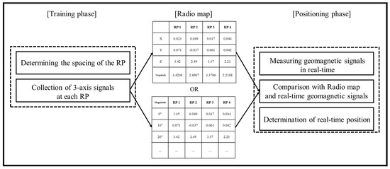
Figure 4.
Flow chart of the traditional geomagnetic fingerprint.
Another method is to store the all 3-axis geomagnetism signals, which is measured for each angle at one RP. This method is robust against the change of the azimuth angle, but it has a disadvantage that the size of the DB increases by 3 times. Therefore, the conventional method has a limit to recognize the position with a single sensor. Therefore, we propose a novel method of ECM-based UFEE that can optimize the position with only the geomagnetic sensor.
3. Proposed ECM Based UFEE
Figure 5 shows the proposed ECM based UFEE. The proposed UFEE divided into the training phase in which an ECM is created using the measured geomagnetic vectors in accordance with each angle, and the positioning phase in which the user position is estimated. In the training phase, to enable position recognition by angle, five randomly measured 3-axis geomagnetism signals are collected by rotating the geomagnetic sensor at each RP. In order to reduce the deviation of the curvature of the ellipse estimated based on the collected five data, the measured 3-axis geomagnetism signals of the x-axis and the y-axis are applied to the standardized least squares method. In addition, we applied the weighted geomagnetic signal equalization method for an optimal weight value derived from the iterative operation of these values to the z-axis signals to keep the relatively very large z-axis signals equal to the x, y signals. Through this method, the proposed ECM was generated. In the positioning phase, the positions of the user are estimated by comparing the geomagnetism signals measured in real time through the user’s smartphone with the ECM produced in the training phase. The measured geomagnetism x, y, and z-axis signals are assigned to the ellipse equation according to the ellipse coefficients stored in the ECM and estimate the most dominant position among these equations.
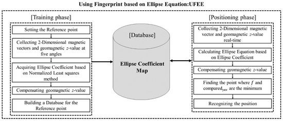
Figure 5.
Flow chart of proposed UFEE(Using Fingerprint based on Ellipse Equation).
3.1. Proposed UFEE in the Training Phase
Unlike the conventional method of storing geomagnetic vectors in a radio map, the proposed UFEE is a novel approach that not only reduces the size of the radio map by storing the ellipse coefficients but also is robust to angle changes. Generally, the 2-D magnetic vector according to the total azimuth angle at one position due to the soft-iron effect and the hard-iron effect appears as an ellipse as shown in Figure 6. The x-axis represents the magnetic vector x measured from the sensor and the y-axis represents the measured value of the magnetic vector y. The points represent 36 geomagnetism signals measured at 10-degree intervals at any one position. The 2-D magnetic vector characteristic output in the form of an ellipse is expressed by an Ellipse Equation as shown in Equation (5).
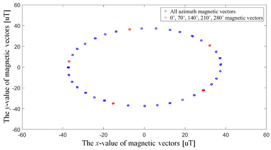
Figure 6.
Characteristics of 2-D magnetic vectors collected using all azimuth angles.
Here, and are the x- and y-axis value of the magnetic vectors, respectively, and a, b, c, d, e, and f are ellipse coefficients that determine the rotation angle, center point, major radius, and minor radius of an ellipse, defined as EC. In order to obtain the ellipse coefficient for outputting the ellipse and to further reflect the characteristic unique to each position, a 2-D magnetic vector with at least five angles is required. Therefore, the proposed UFEE measures the signal at five arbitrary angles like the red dot while rotating 360 degrees in order to minimize the measurement process. As in the red dots in Figure 6, the ellipse equation is derived by acquiring five 2-D magnetic vectors collected at 0, 70, 140, 210 and 280°, respectively.
By acquiring five signals, five equations can be obtained and thus the variables to in Equation (5) can be derived. In this case, since the measured geomagnetism values are reduced, when the values are transformed into elliptical equations, a curvature deviation occurs, resulting in an error between the equations measured at intervals of 10 degrees and the proposed equations. Therefore, the normalized linear least squares method is applied to minimize such curvature deflection. To avoid the situation where all coefficients have a value of 0, the parameter f is normalized to fit the ellipse coefficient by determining f = 1, which is an optimal coefficient for the ellipse having a small radius of curvature around the origin [17]. The normalized least-squares method can then be expressed in terms of the pseudo-inverse as
where
Thus, when the 2-D magnetic vectors of five angles are collected at the same position, the optimal ellipse coefficient can be obtained through the normalized least square method. The coefficients of the obtained ellipses are the conversion equations for the measured geomagnetism x- and y-axis values. Therefore, the geomagnetism values of the acquired z-axis must be considered for positioning factor in order to improve the positioning accuracy. In general, the Euclidean distance, which is the position estimation method used in the positioning phase in the indoor positioning system, is the simplest and fastest algorithm to determine the similarity between two values to be compared. Since this algorithm uses the method of summing the difference of all the values to be compared, when any one of these values is very large, the result is greatly influenced by the large value. On the other hand, when any one of these values is very small, the value is a very low effect on the positioning, enough to be ignored. In order to improve the positioning accuracy, the variables to be compared in the positioning phase include not only the proposed ellipse coefficient (a to f) but also the measured z-axis geomagnetism values in real-time. However, z-axis geomagnetism values are relatively too large compared to the ellipse coefficients. Therefore, in order to maintain the same effect of ellipse coefficients and z in the positioning phase, the z-axis geomagnetism values are equalized before being stored in the database. The weighted geomagnetic signal equalization method is defined as follows.
where is the compensated z-axis geomagnetism value by the weighted geomagnetic signal equalization method, is the ratio to compensate the z-axis geomagnetism value, and is the z-axis geomagnetic value. is determined by the geomagnetism values measured to produce the database at each RP. Based on the geomagnetism z-axis values and the a to f values derived from the geomagnetism values measured in the geomagnetism x- and y-axes, the optimal is derived through an iterative comparison of the positioning result by Euclidean distance using the elements and real measured positions. Since this is different in the range of geomagnetism to be measured for each indoor environment, it is essential to derive a suitable for the applied indoor environment. After the weighted geomagnetic signal equalization method, the database is created using the ellipse coefficient and .
Figure 7 shows the DB structure built from the “EC” via the ellipse equation and the compensated geomagnetic z-values via the weighted geomagnetic signal equalization method.
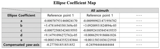
Figure 7.
Configuration of the proposed ellipse coefficient map.
Unlike existing databases, which store geomagnetism intensity and angular values, the proposed database stores the elements derived by using the geomagnetism x-, y-, and z-axis values measured five times at each RP. The x-axis represents the RP, which represents each measurement position, and the y-axis consists of the ellipse coefficients at each RP and . At this time, as mentioned above, the value of f is equal to 1, so it is not necessary to store it separately. Therefore, in the positioning phase, it is possible to estimate the position of all angles by storing only five elliptic coefficients and one compensated yaw-axis at one position.
3.2. The UFEE in Positioning Phase
The positioning phase estimates the position based on the ellipse coefficient map constructed in the training phase. The collected real-time two-dimensional magnetic vectors and geomagnetism z-values at arbitrary positions can be expressed as follows:
where, is the real-time geomagnetism value, and are the x- and y-values of the real-time magnetic vectors, and are the real-time geomagnetism z-values. (1) The real time two-dimensional magnetic vectors are calculated via the ellipse equation built in the ellipse coefficient map, which can be expressed as follows:
where , , , , and e are the , and n is the number of reference points. Since f is set to one in the training phase, f is shifted to the right-hand side and compensated by one in the positioning phase, such that the result of the left-hand side takes an absolute value. Therefore, the minimum f value yields the estimated position. (2) The real-time geomagnetism z-values are calculated via the in the ellipse coefficient map, which can be expressed as
where represents the compensated geomagnetism z-values constructed in the ECM using the reference points, represents the compensated real-time geomagnetism z-values and is derived by comparing the absolute values of and . Therefore, the minimum value yields the estimated position. The result of method (2) should be smoothed with the result of method (1), such that no weighting is introduced in either method. Figure 8 shows the results for the optimal in the basic experiment. Here the x-, y-, and z-axes refer to the reference points, , and positioning accuracy, respectively. The positioning accuracy of 1000 iterations was compared for in the to range based on the collected 2D magnetic vectors and geomagnetism z-values. When dividing the sections along the y-z and x-z axes, the curvature and average positioning accuracy values are maximized when is . The optimal is therefore unaffected when the weighting for each component is . After applying the ratio, the process of comparing with the Ellipse Coefficient Map in real-time is as follows as
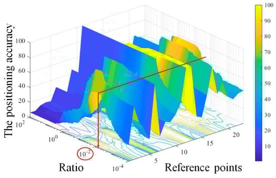
Figure 8.
Change in positioning accuracy by ratio adjustment.
Here, , which has the smallest value among calculated for each position , is estimated as the final position of the user. This means that the difference between the stored values and the real-time measurement is the smallest.
4. Experiment Setup and Results
4.1. Experiment Setup
As with Wi-Fi Fingerprint, which has been widely studied in indoor positioning, a 3 m reference point interval is commonly designated. Therefore, the reference points were set at intervals of 3 m and the system was constructed. In this case, two systems can be built at the same time. The experimental spaces are shown in Figure 9. To verify geomagnetic characteristics and positioning accuracy, we selected the 1st building of the Korea Maritime and Ocean University, which consists of indoor common corridors and rooms. Experiments were conducted on the 2nd to 4th floors to verify the characteristics in the space of 48 m × 30 m. The experiments were conducted on three floors, with 23 reference points collected per floor. A low-cost geomagnetic sensor (YAS537) that is installed in many smartphone devices was used to collect the geomagnetism values.
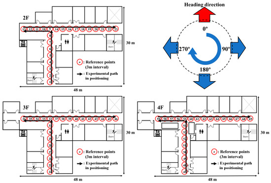
Figure 9.
Experimental space and reference points.
The geomagnetic signals were collected at 30 data points, with a 10° rotation sensor resolution at each reference point. Fifteen data points were obtained at 0, 70, 140, 210 and 280° azimuths to construct the ellipse coefficient map, and the other 15 data points were used for positioning each reference point.
4.2. Experiment Results
The result of positioning using the geomagnetic signal obtained according to the azimuth angle is shown in Figure 10. The x-axis is the reference position, and the y-axis is the frequency obtained from the position. Experiments based on 15 values (36 × 15 = 540) per angle in 36 angles were performed. Here, the blue dot and the line are a method using magnitudes of the geomagnetic intensity based fingerprint (MGIF), and the average value of the geomagnetic total intensity with respect to all directions at the same position is constructed as a database and the location is estimated by calculating the geomagnetic intensity. The yellow dot and line are a method using Fingerprint based on the ellipse equation (UFEE). This is a method of estimating the position of a vector by computing with an ellipse coefficient map. The red dot and line indicate the position recognition result using the smoothing technique in the proposed method.
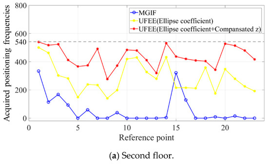
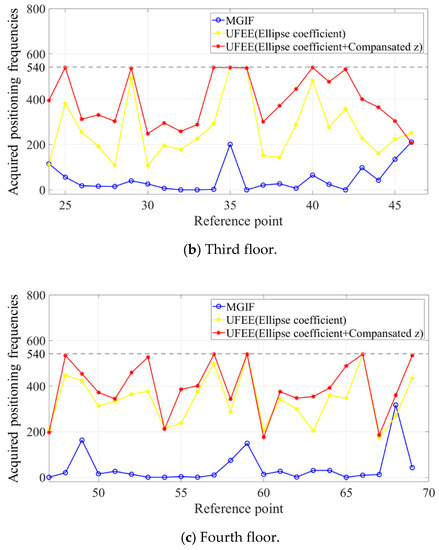
Figure 10.
The acquired positioning frequencies of existing and proposed methods (a) second floor; (b) third floor; (c) fourth floor.
Figure 11 shows the positioning results from the existing method (MGIF) [10] and UFEE for each floor. The x- and y-axes represent the reference points and position results, respectively, with the positions estimated according to the movement path. The results are displayed in a confusion matrix to express all the estimated positions according to the reference points. The positioning accuracy improves as the x = y diagonal becomes clearer. The display color becomes hotter (yellow) as more points recognize the same position and it becomes colder (blue) as fewer points recognize the same position.
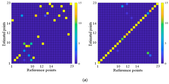
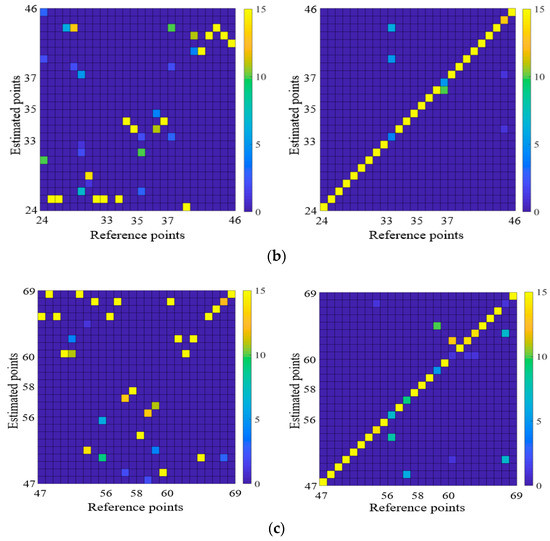
Figure 11.
Positioning results by MGIF and proposed UFEE as (a) a confusion matrix of positioning at the second floor; (b) a confusion matrix of positioning at the third floor; (c) a confusion matrix of positioning at the fourth floor.
The MGIF uses the values of the total intensity of the geomagnetism, it is insensitive to the changes of their total value geomagnetic intensity even though the individual axis signals are show changes, and an error is recognized at multiple different positions having approximately similar values. However, given that the UFEE is compared with the EC extracted from the geomagnetism value of each reference point, and the recognition rate is high even if the geomagnetism values change and this recognition rate is better for positioning because the signal is equalized to reflect the characteristics of the individual axis signals. The confusion matrix shows that the existing method primarily deviated from the diagonal where accurate positioning was judged. The UFEE confirms that the estimated positions match most reference points. The positioning accuracy and distance errors results for the MGIF and UFEE are provided in Table 1 and Table 2.

Table 1.
Comparison of positioning accuracy.
Table 2.
Comparison of error distance.
5. Conclusions
The existing geomagnetic based indoor positioning has been actively studied because it has stable received signals and high positioning resolution because of its high positioning accuracy even over time. However, positioning errors occurs because the geomagnetism values by the azimuth change are not constant even at the same location. In this paper, we propose a novel indoor positioning algorithm based geomagnetic fingerprint that fuses 2-Dimensional geomagnetic vectors and the weighted geomagnetic signal equalization method, called UFEE. In the proposed UFEE, the curvature is less biased heavily by using the ellipse coefficient map of the geomagnetism based on the normalized linear least squares method even when the database size was reduced, and the accuracy of positioning was improved by applying the weighted geomagnetic signal equalization method. To verify the validity of the proposed algorithm in general indoor spaces of 48 m × 30 m, the results of the proposed method were compared with results obtained existing research based on geomagnetism intensity. The results show that the positioning accuracy was improved by 62.14% and the error distance was reduced by 3.98 m.
Author Contributions
Conceptualization, J.-H.S. and S.-H.L.; methodology, J.-H.S.; software, S.-H.L.; validation, K.-K.Y. and D.-H.S.; formal analysis, K.-K.Y.; investigation, K.-K.Y.; resources, J.-H.S.; data curation, S.-H.L.; Writing—Original Draft preparation, J.-H.S.; Writing—Review and Editing, J.H.S.; visualization, S.-H.L.; supervision, D.-H.S.; project administration, D.-H.S.; funding acquisition, D.-H.S.
Funding
This research was supported by Basic Science Research Program through the National Research Foundation of Korea (NRF) funded by the Ministry of Education (No.2016R1D1A1B03934812).
Acknowledgments
This paper is based on Seung-Hyun Lee’s master’s thesis (“A Study on Indoor Positioning using 3-Dimensionalization Geomagnetic Fingerprint, Graduate School of Korea Maritime University”).
Conflicts of Interest
The authors declare no conflict of interest.
References
- Seong, J.H.; Choi, E.C.; Lee, J.S.; Seo, D.H. High-speed positioning and automatic updating technique using Wi-Fi and UWB in a ship. Wirel. Pers. Commun. 2017, 94, 1105–1121. [Google Scholar] [CrossRef]
- Seong, J.H.; Seo, D.H. Environment adaptive localization method using Wi-Fi and Bluetooth low energy. Wirel. Pers. Commun. 2018, 99, 765–778. [Google Scholar] [CrossRef]
- Liu, Z.; Zhang, L.; Liu, Q.; Yin, Y.; Cheng, L.; Zimmermann, R. Fusion of magnetic and visual sensors for indoor localization: Infrastructure-free and more effective. IEEE Trans. Multimedia 2017, 19, 874–888. [Google Scholar] [CrossRef]
- Ma, Y.; Dou, Z.; Jiang, Q.; Hou, Z. Basmag: An optimized HMM-based localization system using backward sequences matching algorithm exploiting geomagnetic information. IEEE Sens. J. 2016, 16, 7472–7482. [Google Scholar] [CrossRef]
- Lee, K.M.; Li, M.; Lin, C.Y. Magnetic tensor sensor and way-finding method based on geomagnetic field effects with applications for visually impaired users. IEEE/ASME Trans. Mechatron. 2016, 21, 2694–2704. [Google Scholar] [CrossRef]
- Shu, Y.; Bo, C.; Zhao, C.; Li, L.; Zhao, F. Magicol: indoor localization using pervasive magnetic field and opportunistic WiFi sensing. IEEE J. Sel. Areas Commun. 2015, 33, 1443–1457. [Google Scholar] [CrossRef]
- Bi, Y.; Shamsi, K.; Yuan, J.S.; Jin, Y.; Niemier, M.; Hu, X.S. Tunnel fet current mode logic for dpa-resilient circuit designs. IEEE Trans. Emerg. Top. Comput. 2017, 5, 340–352. [Google Scholar] [CrossRef]
- Zhang, C.; Subbu, K.P.; Luo, J.; Wu, J. GROPING: geomagnetism and crowdsensing powered indoor navigation. IEEE Trans. Mobile Comput. 2015, 14, 387–400. [Google Scholar] [CrossRef]
- Nguyen, K.A.; Luo, Z. Dynamic route prediction with the magnetic field strength for indoor positioning. Int. J. Wirel. Mobile Comput. 2017, 12, 16–35. [Google Scholar] [CrossRef]
- Chung, J.; Donahoe, M.; Schmandt, C.; Kim, I.J.; Razavai, P.; Wiseman, M. Indoor location sensing using geo-magnetism. In Proceedings of the 9th international conference on Mobile systems, applications, and services, Bethesda, MD, USA, 28 June–1 July 2011. [Google Scholar]
- Xie, H.; Gu, T.; Tao, X.; Ye, H.; Liu, J. A reliability-augmented particle filter for magnetic fingerprint based indoor localization on smartphone. IEEE Trans. Mobile Comput. 2016, 15, 1877–1892. [Google Scholar] [CrossRef]
- Li, B.; Gallagher, T.; Dempster, A.G.; Rizos, C. How feasible is the use of magnetic field alone for indoor positioning. In Proceedings of the 2012 International Conference on Indoor Positioning and Indoor Navigation (IPIN), Sydney, NSW, Australia, 13–15 November 2012. [Google Scholar]
- Lucas, C.E.; Richards, T.C. A Novel Technique for Modelling Ship Magnetic Signatures; Atlantic Research Centre: Halifax, NS, Canada, 2015. [Google Scholar]
- Guo, P.; Qiu, H.; Yang, Y.; Ren, Z. The Soft Iron and Hard Iron Calibration Method using Extended Kalman Filter for Attitude and Heading Reference System. In Proceedings of the IEEE/ION Position, Location and Navigation Symposium, Monterey, CA, USA, 5–8 May 2008. [Google Scholar]
- Seong, J.H.; Seo, D.H. Wi-Fi fingerprint using radio map model based on MDLP and euclidean distance based on the Chi squared test. Wirel. Netw. 2018, 1–9. [Google Scholar] [CrossRef]
- Xia, S.; Liu, Y.; Yuan, G.; Zhu, M.; Wang, Z. Indoor fingerprint positioning based on WiFi: An overview. ISPRS Int. J. Geo-Inf. 2017, 6, 135. [Google Scholar] [CrossRef]
- Rosin, P.L. A note on the least squares fitting of ellipses. Pattern Recognit. Lett. 1993, 14, 799–808. [Google Scholar] [CrossRef]
© 2019 by the authors. Licensee MDPI, Basel, Switzerland. This article is an open access article distributed under the terms and conditions of the Creative Commons Attribution (CC BY) license (http://creativecommons.org/licenses/by/4.0/).