Article

Improvement on Meshing Stiffness Algorithms of Gear with Peeling

1
Key Laboratory of Advanced Manufacturing Technology, Beijing University of Technology, Beijing 100124, China
2
School of Mechanical and Electrical Engineering, Beijing University of Chemical Technology, Beijing 100029, China
*
Author to whom correspondence should be addressed.
Symmetry 2019, 11(5), 609; https://doi.org/10.3390/sym11050609
Submission received: 15 March 2019 / Revised: 22 April 2019 / Accepted: 29 April 2019 / Published: 1 May 2019

Abstract

:
This paper investigates the effect of a gear tooth peeling on meshing stiffness of involute gears. The tooth of the gear wheel is symmetric about the axis, and its symmetry will change after the gear spalling, and its meshing stiffness will also change during the meshing process. On this basis, an analytical model was developed, and based on the energy method a meshing stiffness algorithm for the complete meshing process of single gear teeth with peeling gears was proposed. According to the influence of the change of meshing point relative to the peeling position on the meshing stiffness, this algorithm calculates its stiffness separately. The influence of the peeling sizes on mesh stiffness is studied by simulation analysis. As a very important parameter, the study of gear mesh stiffness is of great significance to the monitoring of working conditions and the prevention of sudden failure of the gear box system.

1. Introduction

Gearbox is one of the most important components in mechanical industry and daily life. With constant development of modern industrial technology, fault monitoring of gearbox is more and more valued in research field [1,2,3,4,5,6,7,8,9,10]. As the key component of gearbox, the study of gear fault diagnosis method [11,12,13,14] is of great significance. Meshari et al. [15] carried out an extensive study of gearbox fault and found that failure of gear tooth is one of the leading causes of gearbox fault, and that peeling is one of the common gear failures. Amarnath [16] indicated that peeling often occurs in the early stage of failure for the geared system. Song et al. [17] proposed the combination of the trivalent logic inference theory with the possibility and fuzzy theories. Cui et al. [18] proposed a new concatenated dictionary matching tracking method combining impact dictionary and step dictionary. Operating in the presence of peeling, the contact stress tends to increase enormously in the contact area of the mating teeth surface. The propagation of tooth damage causes instantaneous reduction in tooth stiffness. The vibration signal of gear transmission varies as the stiffness changes.
Subramanian [19] found that with the increase of tooth thickness and height, the gear tooth stiffness increases, which in turn reduces the radial load deflection and the vibration amplitude in the vertical direction. This shows that time-varying meshing is one of the main inner excitation sources in gearbox. Solving meshing stiffness accurately is the basic condition to research on the fault mechanism of a gear system. Lin [20] simplified finite element with Fourier function to extract the meshing stiffness of different locations, and received a square wave function of meshing stiffness. It is only applied for some specific situations. Silurian ishikawa [21] proposed a method to simplify the involute part into a trapezoid and the transition curve part into a rectangle. This method can calculate the mesh stiffness of the gear more accurately, but the difference between the simplified tooth shape and the actual tooth shape is large. Weber [22] first proposed a method to calculate the meshing stiffness of gears based on the actual involute profile of gears-energy method. Moreover, he derived the Weber–Banaschek formula to calculate the meshing stiffness of gears. Yang and Lin [23] provided synthetical stiffness expression about rotation angle, which is just theoretical research without validation. Wang QB [24] calculated the helical gear meshing stiffness through the energy method, and two cases are presented for validation of the model.
Wang Xi [25] calculated the meshing stiffness of crack of gear with crack by the linear influence line method, and set the crack in the gear pitch circle. Mohammed [26] introduced crack tooth model by finite element method, and drew a parabola from the root of the crack to the vertex of the tooth by observing stress distribution at tooth root fault. The method is called ‘curve influence line’ to replace the straight influence line.
For meshing stiffness of gear with peeling, based on the meshing stiffness formula of Yang and Lin, Tian [27] considered the failure of peeling, crack, and fracture, and considered the shear potential energy innovatively, so the formula of meshing stiffness corresponding to the fault type was put forward. Based on the potential energy method, Zhao Shubin [28] studied the time-varying meshing stiffness of the peeled out gear, and calculated the time-varying meshing stiffness of different peeling sizes. Fernando [29] presented a model for the calculation of meshing forces and meshing stiffness, where deformation was considered. In addition, the effect of the transmitted torque on the meshing stiffness was studied, which is crucial for the dynamic behavior of spur gear transmissions. Shao Yimin [30] studied the change of mesh stiffness at the time of the end of peeling boundaries. Fernando [31,32] presented a developed model to simulate gear transmission dynamics. The developed model is capable of considering simultaneously the internal excitations due to the variable meshing stiffness and other excitations. Ankur Saxen [33] studied the mesh stiffness of different peeling sizes, positions, and shapes, taking into account the influence of the rotational speed on the meshing stiffness.
At present, there are still some limitations in the algorithm to calculate the meshing stiffness of gear with peeling fault. Existing research found that when the gear fault tooth contacts with another gear in a meshing cycle, the contact point gradually moves from the root of the fault tooth to the top of the tooth. The traditional calculation methods only consider the change of contact stiffness when the contact point is in the fault area, but do not consider the change of meshing stiffness when the contact point leaves the fault area. This leads to a large error in the actual meshing stiffness. In order to reduce the error, an improved meshing stiffness algorithm for gear peeling fault is proposed in this paper. The algorithm includes three meshing stages: (1) before entering the peeling fault; (2) during passing through the peeling fault; and (3) after leaving peeling fault. The stiffness calculation models of the three stages are as follows: the first meshing stage is considered as the normal gear model; the second meshing stage is considered as the peeling model; and the third meshing stage is considered as the crack model. Based on the three models, the stiffness calculation formulas of each stage are derived. The proposed algorithm takes the influence of the peeling cavity on the subsequent meshing process into account and makes up for the deficiencies of the current algorithms, so that the time-varying meshing stiffness of the peeling fault can be closer to the actual and provide the parameter support for the dynamic response model of the gear system. Based on the established model, the influence of varying peeling depth and width on time-varying meshing stiffness is studied.

2. The Algorithm Model of Meshing Stiffness

To solve the time-varying meshing stiffness of gear system, the gear model needs to be established first. As shown in Table 1 for the gear model geometry parameters.

2.1. Calculate Hertz Contact Stiffness and Wheel Stiffness

When calculating the gear meshing stiffness by the energy method, it is assumed that the gear body is an isotropic elastomer. According to the law of Hertz, the elastic compression deformation in contact area of two isotropic elastomers can be approximately equivalent to that of parabolic contact. Based on the literature [34], Hertz contact stiffness of a meshing gear pair with same material is a constant on the meshing line, whose value is relatively independent of the position of meshing contact.
The Hertz contact stiffness can be calculated by the formula [27]:
K h = π E L 4 ( 1 ν 2 )
where E is the elastic modulus, L is axial width of the gear, and v is the Poisson’s ratio. According to Formula (1), when the gear material is determined, the Hertz contact stiffness of the gear is proportional to the tooth width.
The meshing stiffness of gear pair also includes wheel body stiffness Kf. The formula can be expressed as [25]:
1 K f = c o s 2 α 1 E L { L * ( u f s f ) + M * ( u f s f ) + P * ( 1 + Q * t a n 2 α 1 ) }
The coefficients L*, M*, P* can be obtained from the formula [35]
X * = A θ f 2 + B h f 2 + C h f 2 θ f 2 + D θ f + E h f 2 + F
where coefficient X* means L*, M*, P*, Q*, and the other parameters can refer to Figure 1. The coefficients A, B, C, D, E and F are shown in Table 2. When calculating L*, it takes the values of A, B, C, D, E, and F of the corresponding row of L*, then, add them into Formula (3) to calculate L*.

2.2. Calculate Bending Stiffness, Shear Stiffness, and Compression Stiffness

Figure 2 shows the forces loaded on the tooth, where F is the meshing force at meshing point. With material mechanics, bending potential energy Ub, shear potential energy Us, and axial compression potential energy Ua is respectively [27]:
U b = F 2 2 k b U s = F 2 2 k s U a = F 2 2 k a
where Kb, Ks, Ka respectively represent the bending stiffness, shear stiffness, and compression stiffness.
According to the cantilever beam theory, bending potential energy Ub, shear potential energy Us, and axial compression potential energy Ua can be calculated with:
K b = 0 d ( y cos ( α 1 ) h x sin ( α 1 ) ) 2 E I x d y
K s = 0 d 1.2 cos 2 ( α 1 ) G A x d y
K a = 0 d sin 2 ( α 1 ) E A x d y
The contact ratio of spur gear is between 1 and 2, so the integral meshing cycle of gear pair includes meshing intervals of single teeth pair and two teeth pair. It is necessary to study the accurate relations between meshing angle and intervals of single and double pair of teeth for meshing stiffness of integral gear pair.
In the stage of single pair of teeth meshing, Hertz stiffness, gear body stiffness, bending stiffness, shear stiffness, and compression stiffness come together into meshing stiffness Kt of a meshing teeth pair. It can be represented as:
1 K t = 1 K h + 1 K b 1 + 1 K s 1 + 1 K a 1 + 1 K f 1 + 1 K b 2 + 1 K s 2 + 1 K a 2 + 1 K f 2
In a double pair of teeth, define the left tooth pair as the first one, i = 1; the right pair as the second, i = 2. Then, the meshing stiffness Kt of a tooth pair can be represented as:
1 K t , i = 1 K h + 1 K b 1 , i + 1 K s 1 i , + 1 K a 1 , i + 1 K f 1 + 1 K b 2 , i + 1 K s 2 , i + 1 K a 2 , i + 1 K f 2

3. Improvement on Meshing Stiffness Algorithms of Gear with Peeling

Ankur [33] solved the meshing stiffness of gear with peeling based on the energy method and studied the meshing stiffness of different sizes, positions, and shapes. Figure 3 presents the peeling failure meshing stiffness in the literature. According to Figure 3, the meshing stiffness algorithm model used in the literature only considers the influence of the peeling interval on the meshing stiffness, but does not consider the influence of peeling interval on the subsequent meshing process.
Mohammed et al. [37] pointed out that although the gear crack would not change the shape of the tooth profile, it would affect the mesh stiffness, and the same goes for peeling. The gear model with peeling as shown in Figure 4 is established. The model divides the gear teeth into three regions. When the meshing point is located in region 1, the meshing stiffness is not affected by peeling; when entering area 2, due to the gear tooth profile being incomplete, there is a sudden change in meshing stiffness; in area 3, despite the complete tooth profile, due to the presence of peeling cavities, peeling failure continues to affect the subsequent meshing stiffness, and the form of influence can be analogized as a crack fault.

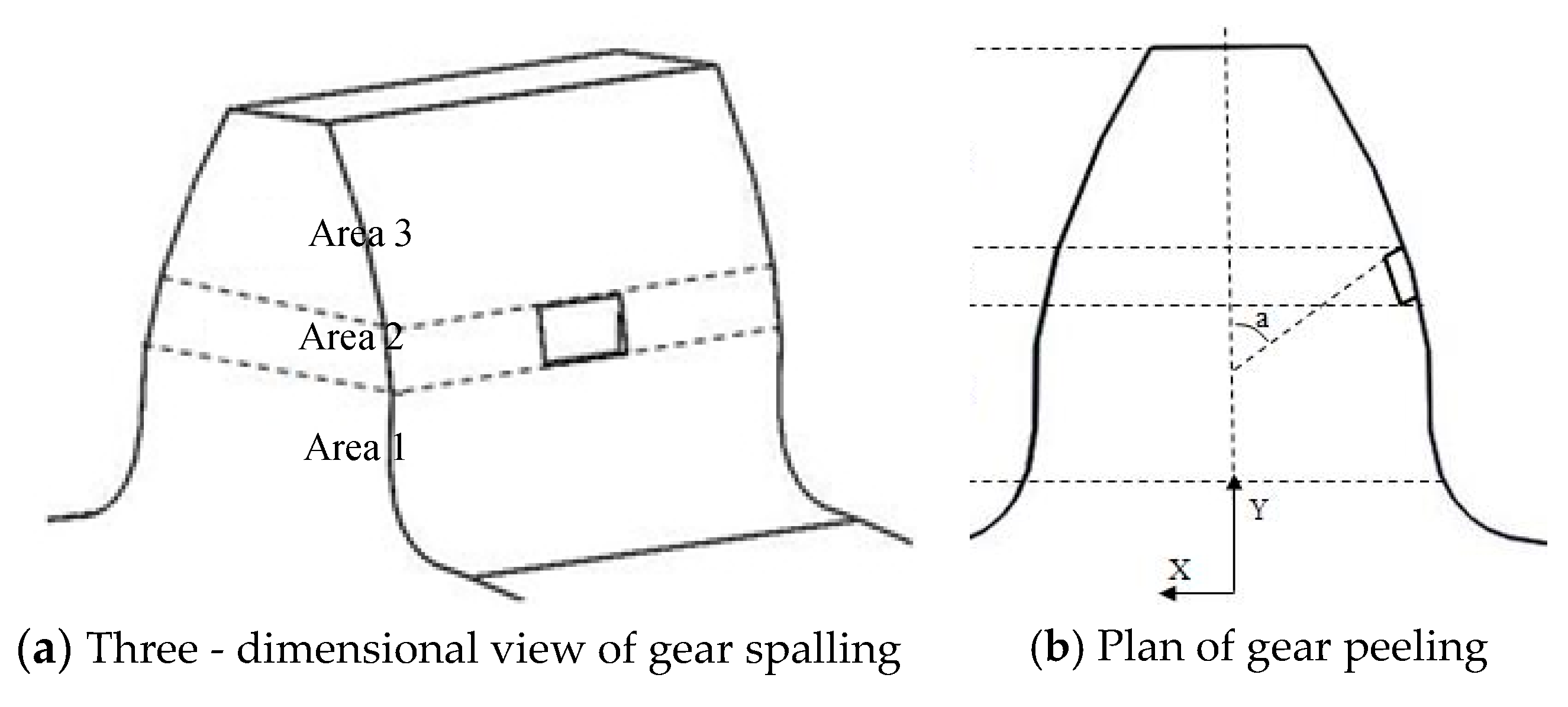
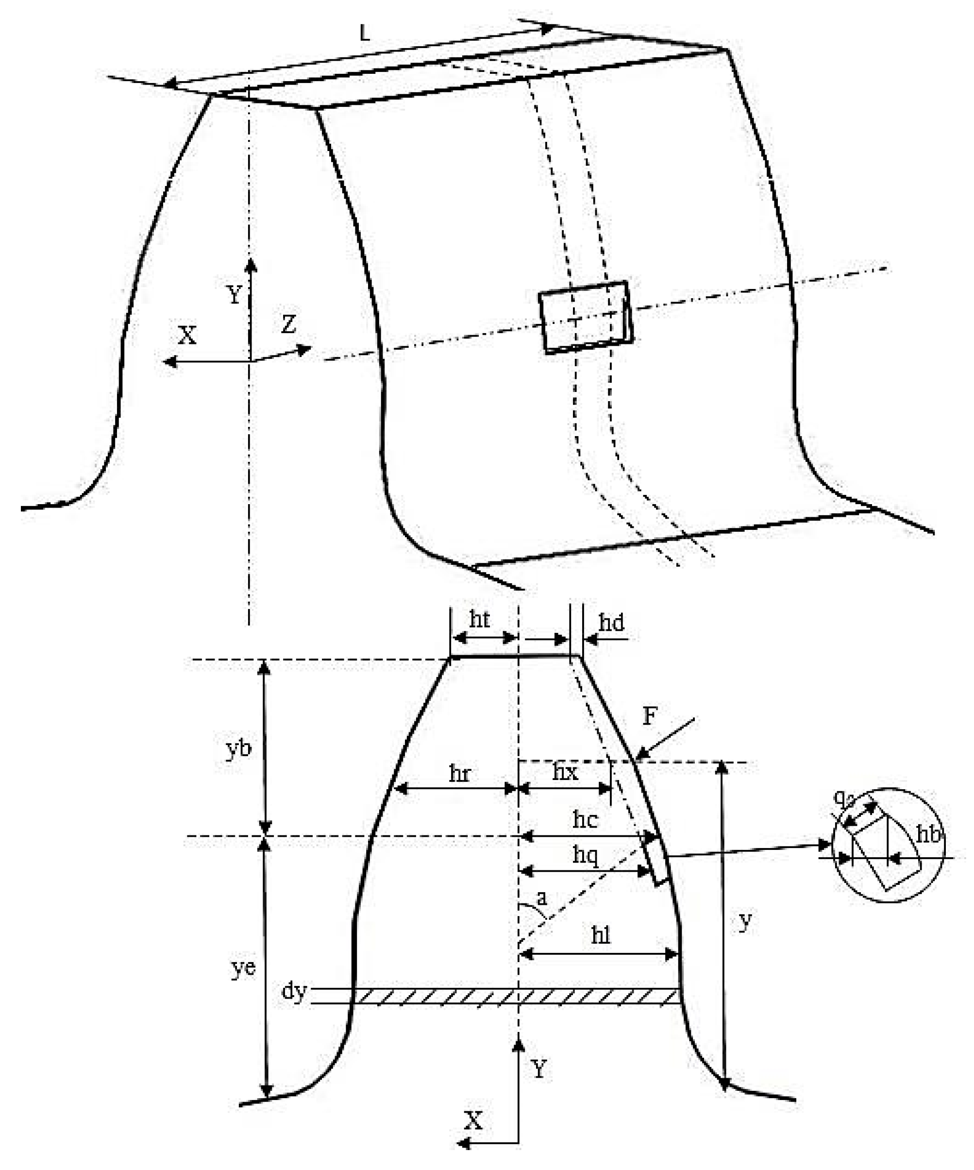
3.1. Establishing a Calculation Model of Peeling Failure Meshing Stiffness

As shown in Figure 5, a gear parameter model with peeling was established. Based on the fault model, the time-varying meshing stiffness of peeling gear was solved. Three assumptions were made on the model:
1. The peeling fault is rectangular, the peeling depth is the same, and the shape of the peeling is symmetrical about the central axis;
2. Before entering the peeling fault, peeling failure has no effect on mesh stiffness;
3. There is quantitative relation: h d h t = h b h c , where h b < h c , or consider the tooth as failure.
Part of the peeling fault parameters are presented in Table 3.
For the peeling fault, the meshing stiffness K is solved in five parts, respectively, K1, K2, K3, Kh, and Kfi, and the formulas are:
1 K = 1 K 1 + 1 K 2 + 1 K 3 + 1 K h + 1 K f i ( i = 1 , 2 )
{ K 1 = 1 1 K b 1 , i + 1 K s 1 i , + 1 K a 1 , i + 1 K b 2 , i + 1 K s 2 , i + 1 K a 2 , i ( 0 Z W 1 , 0 Y Y 3 , i = 1 , 2 ) K 2 = { K 2 , 1 ( W 1 Z W 1 + W 2 , 0 Y Y 1 ) K 2 , 2 ( W 1 Z W 1 + W 2 , Y 1 Y Y 1 + Y 2 ) K 2 , 3 ( W 1 Z W 1 + W 2 , Y 2 Y Y 2 + Y 3 ) K 3 = 1 1 K b 1 , i + 1 K s 1 i , + 1 K a 1 , i + 1 K b 2 , i + 1 K s 2 , i + 1 K a 2 , i ( W 2 Z W 2 + W 3 , 0 Y Y 3 , i = 1 , 2 ) K h = { π E L i 4 ( 1 ν 2 ) ( o t h e r ) 0 ( W 1 Z W 1 + W 2 , Y 1 Y Y 1 + Y 2 )

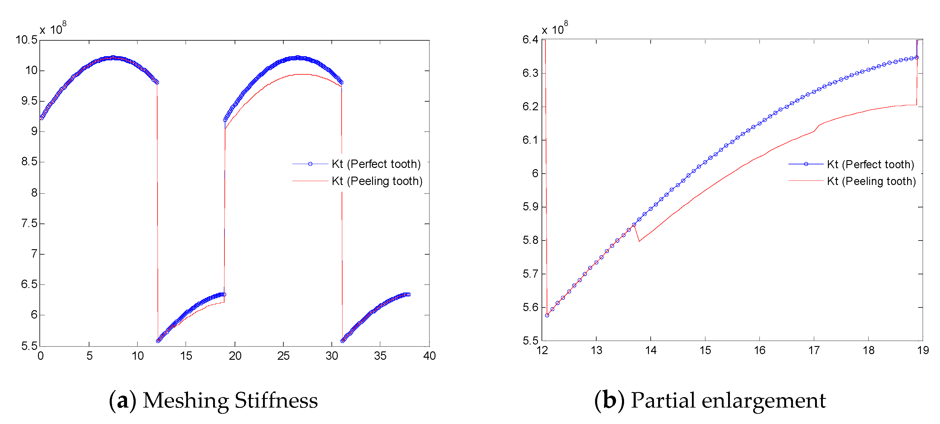
3.2. Solve Peeling Failure Meshing Stiffness

With the energy method and geometrical characteristics of the asymptote gear, the bending stiffness Kb, shear stiffness Ks, and compression stiffness Ka can be calculated with:
K b = 0 d ( y cos ( α 1 ) h x sin ( α 1 ) ) 2 E I x d y
K s = 0 d 1.2 cos 2 ( α 1 ) G A x d y
K a = 0 d sin 2 ( α 1 ) E A x d y
Shear module G: G = E 2 ( 1 + υ )
I x —rotation inertia, A x —CSA (cross sectional area)
I x = { 2 3 ( h r + h l ) 3 W 1 , ( 0 Z W 1 , 0 Y Y 3 ) 2 3 ( h r + h l ) 3 W 2 , ( W 1 Z W 1 + W 2 , 0 Y Y 1 ) 1 12 ( h l + h q ) 3 W 2 , ( W 1 Z W 1 + W 2 , Y 1 Y Y 1 + Y 2 ) 2 3 ( h l + h x ) 3 W 2 , ( W 1 Z W 1 + W 2 , Y 1 + Y 2 Y Y 1 + Y 2 + Y 3 ) 2 3 ( h r + h l ) 3 W 3 , ( W 1 + W 2 Z W 1 + W 2 + W 3 , 0 Y Y 3 )
A x = { ( h l + h r ) W 1 , ( 0 Z W 1 , 0 Y Y 3 ) ( h l + h r ) W 2 , ( W 1 Z W 1 + W 2 , 0 Y Y 1 ) ( h l + h q ) W 2 , ( W 1 Z W 1 + W 2 , Y 1 Y Y 1 + Y 2 ) ( h l + h x ) W 2 , ( W 1 Z W 1 + W 2 , Y 1 + Y 2 Y Y 1 + Y 2 + Y 3 ) ( h l + h r ) W 3 , ( W 1 + W 2 Z W 1 + W 2 + W 3 , 0 Y Y 3 )
There is a quantitative relationship:
{ h d h t = h b h c h x = h t h e h d y b ( y y e ) + h e
Therefore, I x , A x can be deduced:
I x = 1 12 ( h l + y b h d h e ( y y e ) + h e ) 3 W 2 , ( W 1 Z W 1 + W 2 , Y 1 + Y 2 Y Y 1 + Y 2 + Y 3 )
A x = ( h l + y b h d h e ( y y e ) + h e ) W 2 , ( W 1 Z W 1 + W 2 , Y 1 + Y 2 Y Y 1 + Y 2 + Y 3 )
Among them, the parameters hl, hq, y, and dy can be expressed as:
{ h l = R b [ ( α + α 2 ) cos α sin α ] h q = R b [ ( α + α 2 ) cos α sin α ]
y = R b [ cos α ( α 2 α ) sin α cos α 2 ]
d y = R b ( α α 2 ) cos α d α
When 0 Z W 1 , 0 Y Y 1 + Y 2 + Y 3 W 1 + W 2 Z W 1 + W 2 + W 3 , 0 Y Y 1 + Y 2 + Y 3 , bending stiffness Kb, shear stiffness Ks, and compression stiffness Ka can be integrated with:
{ K b = α 1 α 2 ( R b [ cos α ( α 2 α ) sin α cos α 2 ] cos ( α 1 ) R b [ ( α + α 2 ) cos α sin α ] sin ( α 1 ) ) 2 2 3 E ( R b [ ( α + α 2 ) cos α sin α ] ) 3 W 1 R b ( α α 2 ) cos α d α K s = α 1 α 2 0.6 cos 2 ( α 1 ) G R b [ ( α + α 2 ) cos α sin α ] W 1 R b ( α α 2 ) cos α d α K a = a 1 a 2 sin 2 ( α 1 ) 2 E R b [ ( α + α 2 ) cos α sin α ] W 1 R b ( α α 2 ) cos α d α
When ( W 1 Z W 1 + W 2 , 0 Y Y 1 + Y 2 + Y 3 ) :
{ K b = α 1 α 2 ( R b [ cos α ( α 2 α ) sin α cos α 2 ] cos ( α 1 ) R b [ ( α + α 2 ) cos α sin α ] sin ( α 1 ) ) 2 2 3 E ( R b [ ( α + α 2 ) cos α sin α ] ) 3 W 2 R b ( α α 2 ) cos α d α , ( 0 Y Y 1 ) K b = α 1 α 2 ( R b [ cos α ( α 2 α ) sin α cos α 2 ] cos ( α 1 ) R b [ ( α + α 2 ) cos α sin α ] sin ( α 1 ) ) 2 1 12 E ( R b [ ( α + α 2 ) cos α sin α ] + h q ) 3 W 2 R b ( α α 2 ) cos α d α , ( Y 1 Y Y 1 + Y 2 ) K b = α 1 α 2 ( R b [ cos α ( α 2 α ) sin α cos α 2 ] cos ( α 1 ) R b [ ( α + α 2 ) cos α sin α ] sin ( α 1 ) ) 2 1 12 E ( R b [ ( α + α 2 ) cos α sin α ] + y b h d h e ( R b [ cos α ( α 2 α ) sin α cos α 2 ] y e ) + h e ) 3 W 2 R b ( α α 2 ) cos α d α , ( Y 1 + Y 2 Y Y 1 + Y 2 + Y 3 )
{ K s = α 1 α 2 0.6 cos 2 ( α 1 ) G R b [ ( α + α 2 ) cos α sin α ] W 2 R b ( α α 2 ) cos α d α , ( 0 2 Y Y 1 ) K s = α 1 α 2 1.2 cos 2 ( α 1 ) G ( R b [ ( α + α 2 ) cos α sin α ] + h q ) W 2 R b ( α α 2 ) cos α d α , ( Y 1 Y Y 1 + Y 2 ) K s = α 1 α 2 1.2 cos 2 ( α 1 ) G ( R b [ ( α + α 2 ) cos α sin α ] + y b h d h e ( R b [ cos α ( α 2 α ) sin α cos α 2 ] y e ) + h e ) W 2 R b ( α α 2 ) cos α d α , ( Y 1 + Y 2 Y Y 1 + Y 2 + Y 3 )
{ K a = α 1 α 2 sin 2 ( α 1 ) 2 E R b [ ( α + α 2 ) cos α sin α ] W 2 R b ( α α 2 ) cos α d α , ( 0 Y Y 1 ) K a = α 1 α 2 sin 2 ( α 1 ) E ( R b [ ( α + α 2 ) cos α sin α ] + h q ) W 2 R b ( α α 2 ) cos α d α , ( Y 1 Y Y 1 + Y 2 ) K a = α 1 α 2 sin 2 ( α 1 ) 2 E R b [ ( α + α 2 ) cos α sin α ] W 2 R b ( α α 2 ) cos α d α , ( Y 1 + Y 2 Y Y 1 + Y 2 + Y 3 )
The formula parameter is shown in Figure 2. The time-varying meshing stiffness is obtained by MATLAB programming. Figure 6 shows normal gear meshing stiffness and peeling fault meshing stiffness. As shown in Figure 6a, peeling failure occurred in the stage of one pair of tooth meshing. Before entering the fault, the peeling meshing stiffness is the same as normal meshing stiffness; at the moment of entering peeling location, the fault meshing stiffness value decreased suddenly.
It can be seen from Figure 6b that when the angle is 17°, the meshing position leaves a peeling fault and the tooth profile is complete in the process of the subsequent meshing. So, the compressive stiffness and contact stiffness increase, which causes the peeling meshing stiffness to suddenly increase. However, due to the existence of the peeling cavity, the bending stiffness and shearing stiffness are affected; the meshing stiffness is still less than the normal meshing stiffness.

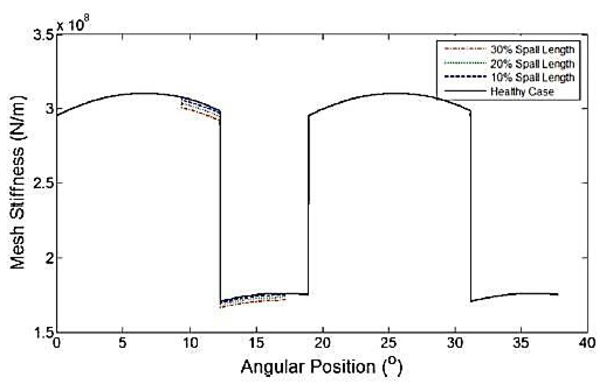
4. The Meshing Stiffness of Gear with Variable Peeling Parameter

In changing the size of the peeling fault, the effect of different fault size on the meshing stiffness can then be studied. It can be seen from the formula that the fault size Y2 mainly affects the division of fault interval, and has no influence on the meshing stiffness. Then, the fault depth q0 and fault width W2 are thoroughly studied in this paper.

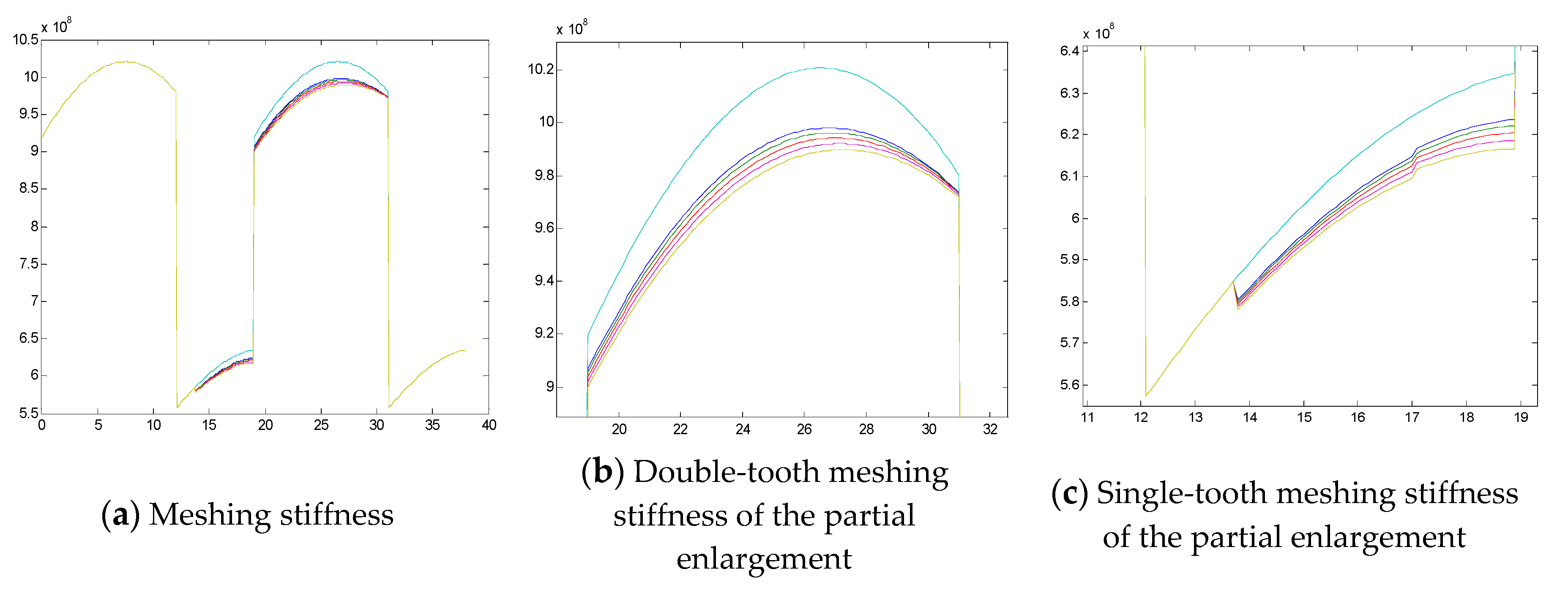
4.1. Variable Depth Variable Meshing Stiffness

In order to study the effect of peeling depth on the time-varying meshing stiffness, the width of the peeling was fixed, the peeling depth was changed, and then variable depth of peeling failure meshing stiffness was calculated. Making a study to compare two groups of size: (1) peeling width 6 mm, peeling depth 1 mm, 1.5 mm, 2 mm, 2.5 mm and 3 mm, respectively; (2) peeling width 16 mm, peeling depth 1 mm, 1.5 mm, 2 mm, 2.5 mm, 3 mm, respectively. The tooth width of the gear model is 16 mm. For group 1, the peeling fault is a partial failure; for group 2, the peeling fault crosses transversely.
Figure 7 shows the meshing stiffness curves corresponding to different peeling depths when the peeling width is 6 mm; the curves shown in the figure are normal meshing stiffness, 1 mm peeling depth meshing stiffness, 1.5 mm peeling depth meshing stiffness, 2 mm peeling depth meshing stiffness, 2.5 mm peeling depth meshing stiffness, and 3 mm peeling depth meshing stiffness from top to bottom. The meshing stiffness with a peeling width of 16 mm is shown in the Figure 8, where the curve is the same as shown in Figure 7. Through comparative study, it can be found that when the peeling width is 6 mm, as the depth of fault expands, the meshing stiffness decreases, but the decrease is small; when the peeling width is 16 mm, as the depth of fault expands, the meshing stiffness decreases, and the reduction is greater. This also shows that when the peeling width is small, the peeling depth has little effect on the meshing stiffness. As the peeling width increases, the peeling depth has a greater impact on the meshing stiffness amplitude.

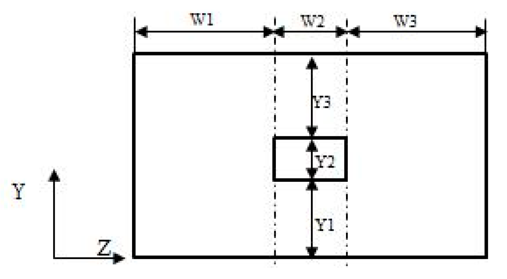
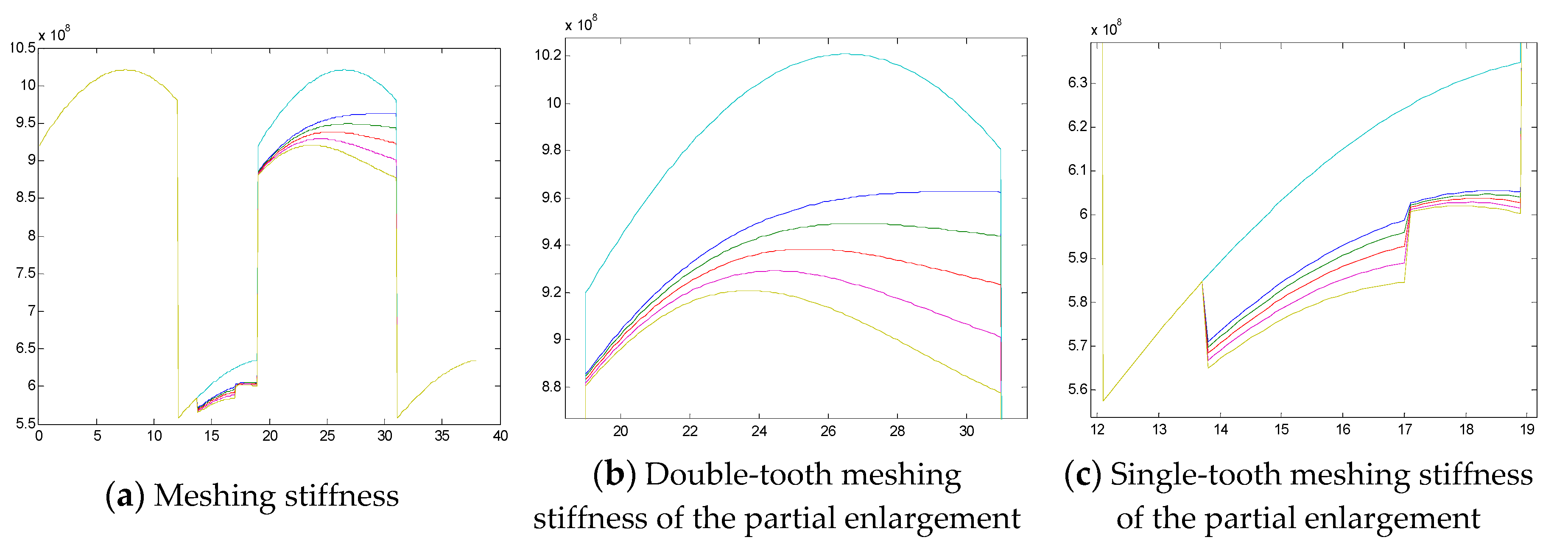
4.2. Variable Width Variable Meshing Stiffness

In order to study the effect of peeling width on the time-varying meshing stiffness, the peeling depth was fixed, the peeling width was changed, and then variable width of peeling failure meshing stiffness was calculated. Peel depth is 3 mm. Peel width is 2 mm, 4 mm, 6 mm, 8 mm, 10 mm, 12 mm, 14 mm, and 16 mm.
Figure 9 shows the meshing stiffness curves corresponding to different peeling widths when the peeling depth is 3 mm; the curves shown in the figure are normal meshing stiffness, 2 mm peeling width meshing stiffness, 4 mm peeling width meshing stiffness increasing to 16 mm peeling width meshing stiffness from top to bottom. From the figure, it can be seen as the peel width increases, the meshing stiffness decreases with the same peel depth. In the project, most of the peeling failures are local peeling, and horizontal peeling rarely occurs. Therefore, comparing Section 3.1 with Section 3.2, it is found that the peeling engagement stiffness is greatly affected by the peeling width, while the peeling depth has less effect on the splicing stiffness by the peeling width.

5. Conclusions

Aiming at the limitation in the existing meshing stiffness algorithm for gear peeling faults, based on the energy method, a gear peeling meshing stiffness algorithm was proposed in this paper. The new algorithm considers the influence of the peeling cavity on the area between the peeling position and the tooth tip. The influence form was analogized as crack fault.
The influence of exfoliation size on mesh stiffness was studied by using the new algorithm. Peeling length has little effect on mesh stiffness. With the increase of peeling depth and width, the meshing stiffness decreases gradually.
For the common local peeling failure, compared with peeling depth, peeling width has more influence on mesh stiffness.

Author Contributions

L.C. and T.L. conceived and designed the experiments. J.F. and T.L. performed the experiments. T.L. and H.W. analyzed the data; L.C. and F.H. provided guidance and recommendations for research; T.L. contributed to the contents and writing of the manuscript. All authors have read and approved the final manuscript.

Funding

Funding was provided by the National Natural Science Foundation of China (Grant Nos. 51575007).

Acknowledgments

The authors would like to gratefully acknowledge the National Natural Science Foundation of China (Grant nos. 51575007) and the Key Laboratory of Advanced Manufacturing Technology for their support. Finally, the authors would like to thank the editors and reviewers for their valuable comments and constructive suggestions.

Conflicts of Interest

The authors declare no conflict of interest.

References

  1. Cui, L.L.; Li, B.B.; Ma, J.F.; Jin, Z. Quantitative trend fault diagnosis of a rolling bearing based on Sparsogram and Lempel-Ziv. Measurement 2018, 128, 410–418. [Google Scholar] [CrossRef]
  2. Song, L.Y.; Wang, H.Q.; Chen, P. Vibration-Based Intelligent Fault Diagnosis for Roller Bearings in Low-Speed Rotating Machinery. IEEE Trans. Instrum. Meas. 2018, 67, 1887–1899. [Google Scholar] [CrossRef]
  3. Cui, L.L.; Wang, X.; Xu, Y.G.; Jiang, H.; Zhou, J.P. A novel Switching Unscented Kalman Filter method for remaining useful life prediction of rolling bearing. Measurement 2019, 135, 678–684. [Google Scholar] [CrossRef]
  4. Han, T.; Jiang, D.; Zhao, Q.; Wang, L.; Yin, K. Comparison of random forest, artificial neural networks and support vector machine for intelligent diagnosis of rotating machinery. Trans. Inst. Meas. Control 2018, 40, 2681–2693. [Google Scholar] [CrossRef]
  5. Cui, L.; Huang, J.; Zhang, F. Quantitative and localization diagnosis of a defective ball bearing based on vertical-horizontal synchronization signal analysis. IEEE Trans. Ind. Electron. 2017, 64, 8695–8705. [Google Scholar] [CrossRef]
  6. 6. Hao, Y.S.; Song, L.Y.; Wang, M.Y.; Cui, L.I.; Wang, H. Underdetermined Source Separation of Bearing Faults Based on Optimized Intrinsic Characteristic-Scale Decomposition and Local Non-Negative Matrix Factorization. IEEE Access 2019, 7, 11427–11435. [Google Scholar] [CrossRef]
  7. Cui, L.; Wang, J.; Lee, S. Matching Pursuit of an Adaptive Impulse Dictionary for Bearing Fault Diagnosis. J. Sound Vib. 2014, 333, 2840–2862. [Google Scholar] [CrossRef]
  8. Wang, H.; Li, S.; Song, L.Y. A novel convolutional neural network based fault recognition method via image fusion of multi-vibration-signals. Comput. Ind. 2019, 105, 182–190. [Google Scholar] [CrossRef]
  9. Cui, L.; Huang, J.F.; Zhang, F.B. HVSRMS localization formula and localization law: Localization diagnosis of a ball bearing outer ring fault. Mech. Syst. Signal Process. 2019, 120, 608–629. [Google Scholar] [CrossRef]
  10. Wang, H.Q.; Ren, B.Y.; Song, L.Y. A Novel Weighted Sparse Representation Classification Strategy based on Dictionary Learning for Rotating Machinery. IEEE Trans. Instrum. Meas. 2019. [Google Scholar] [CrossRef]
  11. Cui, L.L.; Yao, T.C.; Zhang, Y.; Gong, X.Y.; Kang, C.H. Application of pattern recognition in gear faults based on the matching pursuit of a characteristic waveform. Measurement 2017, 104, 212–222. [Google Scholar] [CrossRef]
  12. Hao, Y.; Song, L.; Cui, L.; Wang, H. A three-dimensional geometric features-based SCA algorithm for compound faults diagnosis. Measurement 2019, 134, 480–491. [Google Scholar] [CrossRef]
  13. Cui, L.; Jin, Z.; Huang, J.; Wang, H. Fault severity classification and size estimation for ball bearings based on vibration mechanism. IEEE Access 2019. [Google Scholar] [CrossRef]
  14. Wang, H.; Wang, P.; Song, L. A Novel Feature Enhancement Method based on Improved Constraint Model of Online Dictionary Learning. IEEE Access 2019, 7, 17599–17607. [Google Scholar] [CrossRef]
  15. Al-Meshari, A.; Al-Zahrani, E.; Diab, M. Failure analysis of cooling fan gearbox. Eng. Fail. Anal 2012, 20, 166–172. [Google Scholar] [CrossRef]
  16. Amarnath, M.; Chandramohan, S. Experimental investigations of surface wear assessment of spur gear teeth. J. Vib. Control 2012, 7, 1009–1024. [Google Scholar] [CrossRef]
  17. Subramanian, R.B.; Srinivasan, K. Vibration analysis of an influence of groove in the bottom land of a spur gear. J. Vib. Control 2014, 6, 847–858. [Google Scholar] [CrossRef]
  18. Cui, L.L.; Wang, X.; Wang, H.Q.; Wu, N. Improved Fault Size Estimation Method for Rolling Element Bearings Based on Concatenation Dictionary. IEEE Access 2019, 7, 22710–22718. [Google Scholar] [CrossRef]
  19. Song, L.Y.; Wang, H.Q.; Chen, P. Step-by-step Fuzzy Diagnosis Method for Equipment Based on Symptom Extraction and Trivalent Logic Fuzzy Diagnosis Theory. IEEE Trans. Fuzzy Syst. 2018, 26, 3467–3478. [Google Scholar] [CrossRef]
  20. Lin, J.; Robert, G.P. Mesh stiffness variation instabilities in two-stage gear systems. J. Vib. Acoust. 2002, 124, 68–76. [Google Scholar] [CrossRef]
  21. Li, R.Z. Ring-wheel strength design material. Japan Society of Mechanical Engineers. Mach. Tool Ind. Ed. 1984, 56–58. [Google Scholar]
  22. Weber, C. The deformation of loaded gears and the effect on their load-carrying capacity. In Scientific and Industrial Research in British; EReport No.3; Department of Scientific and Industrial Research: New Delhi, India, 1949. [Google Scholar]
  23. Yang, D.C.H.; Lin, J.Y. Hertzian damping, tooth friction and bending elasticity in gear impact dynamics. J. Mesh. Trans. Auto. Des. 1987, 109, 189–196. [Google Scholar] [CrossRef]
  24. Wang, Q.B.; Zhang, Y.M. A model for analyzing stiffness and stress in a helical gear pair with tooth profile errors. J. Vib. Control 2017, 23, 272–289. [Google Scholar] [CrossRef]
  25. Wang, X. Study on the Calculation of Gear Crack Dynamics and Gear Tooth Crack Stiffness. Master’s Thesis, Chongqing University, Chongqing, China, 2012. [Google Scholar]
  26. Mohammed, O.D.; Rantatalo, M.; AIDANPÄÄ, J.O. Improving mesh stiffness calculation of cracked gears for the purpose of vibration-based fault analysis. Eng. Fail. Anal. 2013, 34, 235–251. [Google Scholar] [CrossRef]
  27. Tian, X.H. Dynamic Simulation for System Response of Gearbox Including Localized Gear Faults. Master’s Thesis, University of Alberta, Edmonton, AB, Canada, 2004. [Google Scholar]
  28. Zhao, S.B.; Hong, R.J. Function law calculation Calculation peeling breakdown time at the time of ringing. Mach. Des. Manuf. 2014, 10, 171–176. [Google Scholar]
  29. Del Rincon, A.F.; Viadero, F.; Iglesias, M.; De-Juan, A.; Garcia, P.; Sancibrian, R. Effect of cracks and pitting defects on gear meshing. Proc. Inst. Mech. Eng. Part C J. Mech. Eng. Sci. 2012, 226, 2805–2815. [Google Scholar] [CrossRef]
  30. Shao, Y.M.; Wang, X.L. Contact surface time hardness surface surface peeling dynamics model robustness application. J. Vib. Shock 2014, 33, 8–14. [Google Scholar]
  31. Fernandez-del-Rincon, A.; Garcia, P.; Diez-Ibarbia, A.; de-Juan, A.; Iglesias, M.; Viadero, F. Enhanced model of gear transmission dynamics for condition monitoring applications: Effects of torque, friction and bearing clearance. Mech. Syst. Signal Process. 2017, 85, 445–467. [Google Scholar] [CrossRef]
  32. Del Rincon, A.F.; de-Juan, A.P.; Garcia, P.A.; Diez-Ibarbia, A.; Viadero, F. Planetary transmission load sharing: Manufacturing errors and system configuration study Iglesias. Mech. Mach. Theory 2017, 111, 21–38. [Google Scholar]
  33. Saxena, A.; Parey, A. Time varying mesh stiffness calculation of spur gear pair considering sliding friction and peeling defects. Eng. Fail. Anal. 2016, 70, 200–211. [Google Scholar] [CrossRef]
  34. Yang, D.C.H.; Sun, Z.S. A Rotary Model for Spur Gear Dynamics. J. Mech. Transm. Autom. Des. 1985, 107, 529–535. [Google Scholar] [CrossRef]
  35. Steward, J.H. Elastic analysis of load distribution in wide-faced spur gears. Master’s Thesis, University of Newcastle, Galan, Australian, 1989. [Google Scholar]
  36. Chen, Z.; Shao, Y. Dynamic simulation of spur gear with tooth root crack propagating along tooth width and crack depth. Eng. Fail. Anal 2011, 18, 2149–2164. [Google Scholar] [CrossRef]
  37. Mohammed, O.D.; Rantatalo, M.; Aidanpää, J.O. Vibration signal analysis for gear fault diagnosis with various crack progression scenarios. Mech. Syst. Signal Process. 2013, 41, 176–195. [Google Scholar] [CrossRef]
Figure 1. Wheel stiffness parameters [36].
Symmetry 11 00609 g001
Figure 2. The force diagram of the tooth [26].
Symmetry 11 00609 g002
Figure 3. The peeling failure meshing stiffness in the literature.
Symmetry 11 00609 g003
Figure 4. Gear model with peeling.
Symmetry 11 00609 g004
Figure 5. Gear parameter model with peeling.
Symmetry 11 00609 g005aSymmetry 11 00609 g005b
Figure 6. Normal Meshing Stiffness and Peeling Meshing Stiffness. (a) is the meshing stiffness curve of spalling gear and healthy gear in the meshing process, The blue curve is the meshing stiffness of the healthy gear, and the red curve is the meshing stiffness of the stripped gear; (b) is a local enlarged view of gear fitting stiffnes.
Symmetry 11 00609 g006
Figure 7. The meshing stiffness with a peeling width of 6 mm.
Symmetry 11 00609 g007
Figure 8. The meshing stiffness with a peeling width of 16 mm.
Symmetry 11 00609 g008
Figure 9. The meshing stiffness with a peeling depth of 3 mm.
Symmetry 11 00609 g009
Table 1. Gear model geometry parameters.
ParametersDrive WheelDriven Wheel
Modulus55
Number of teeth1948
Pressure angle20°20°
Addendum coefficient11
Tip clearance coefficient0.250.25
Elastic Modulus2.06 × 10112.06 × 1011
Poisson’s ratio0.30.3
Tooth width2020
Table 2. Coefficients A, B, C, D, E, F.
AiBiCiDiEiFi
L * ( h , θ f ) −5.574e−5−1.9986e−3−2.3015e−44.7702e−30.02716.8045
M * ( h , θ f ) 60.111e−528.100e−3−83.431e−4−9.9256e−30.16240.9086
P * ( h , θ f ) −50.952e−5185.50e−30.0538e−453.300e−30.28950.9236
Q * ( h , θ f ) −6.2042e−59.0889e−3−4.0964e−47.8297e−3−0.14720.6904
Table 3. Part of the peeling fault parameters.
W 1 W 2 W 3 Y 1 Y 2 Y 3 a
7 mm2 mm7 mm2.5 mm1.0 mm4.33 mm45°

