Article

An Equivalent Damping Numerical Prediction Method for the Ring Damper Used in Gears under Axial Vibration

1
National Key Laboratory of Science and Technology on Helicopter Transmission, Nanjing University of Aeronautics and Astronautics, Nanjing 210016, China
2
AECC Hunan Aviation Powerplant Research Institute, Zhuzhou 412002, China
3
School of Energy and Power Engineering, Beihang University, Beijing 100191, China
*
Authors to whom correspondence should be addressed.
Symmetry 2019, 11(12), 1469; https://doi.org/10.3390/sym11121469
Submission received: 7 November 2019 / Revised: 26 November 2019 / Accepted: 29 November 2019 / Published: 2 December 2019
(This article belongs to the Special Issue Symmetry in Engineering Sciences II)

Abstract

:
In aircraft gas turbine engines, gears in the transmission system are typically cyclic in structure and inevitably encounter large dynamic loads, such as meshing excitation, resulting in high vibration loads in resonance. To prevent gear resonance failure, a ring damper is employed to reduce the resonance response. As relative motion between the gear and the ring damper occurs, vibration loads can be reduced by friction energy dissipation. Moreover, the gears in the aircraft engine are thin-walled and their axial stiffness is much smaller than radial stiffness; thus, it is easier for axial vibration to cause resonance failure. This paper proposes an equivalent damping numerical prediction method for a ring damper under axial vibration, which greatly shortens the calculation time and prevents the forced response analysis of nonlinear structures. Via this method, the influence of ring damper structural parameters on friction damping in gears under axial vibration is investigated. The results indicate that the friction coefficient and mass of the ring damper have a great influence on damping performance.

1. Introduction

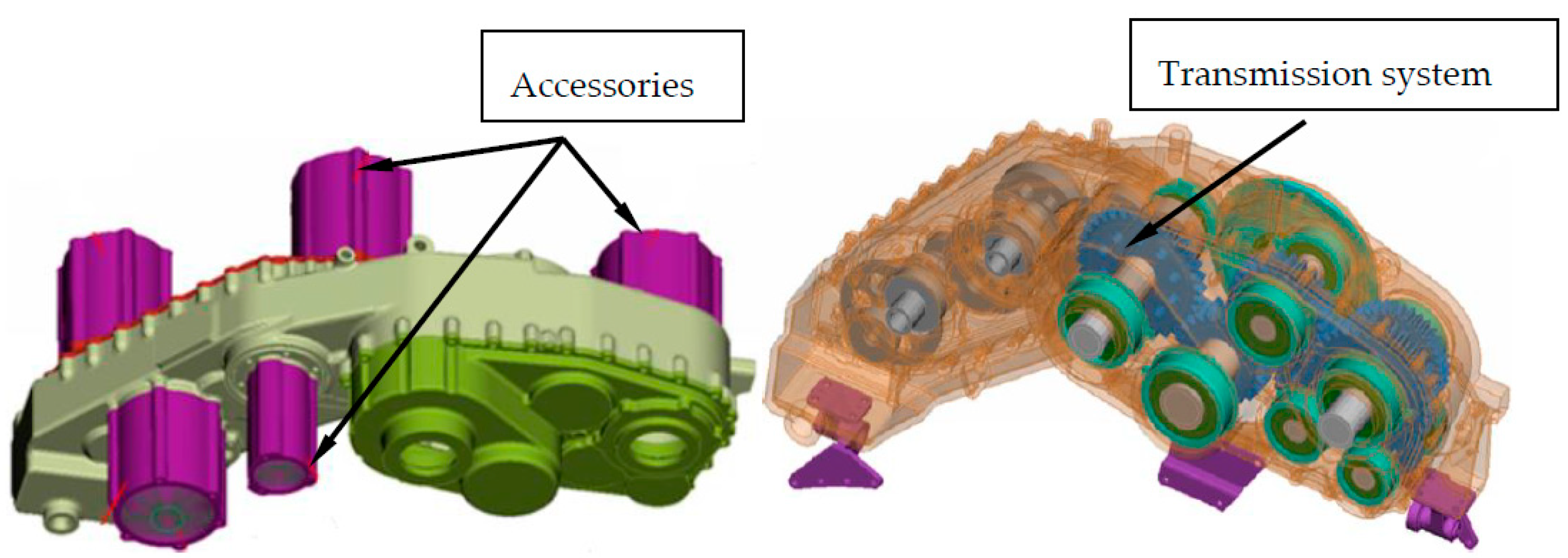
In an aircraft’s gas turbine engine, the transmission system transmits power to accessories, such as the oil pump (as shown in Figure 1). In order to reduce the weight of the engine, the transmission gears often have a thin-walled structure. However, these gears also easily cause resonance in the operating speed range, stressing on the need to reduce vibration and avoid resonance failure. Common strategies to prevent this include active and passive damping. Active damping involves redesigning of the gear structure to limit resonance points in the operating range; this is difficult to realize in an aircraft gas turbine engine, where multiple resonance points exist. The passive method utilizes damping devices to increase system damping and subsequently suppress vibration [1]. The ring damper is one such device; its structure is shown in Figure 2.
A ring damper is a device used to improve the damping of gears. Via relative motion on the contact interface between the ring damper and the gear, vibration energy is dissipated and vibration amplitude/stress is reduced [2].
Most research is currently focused on analyzing the forced response of the structure with an additional ring damper. Laxalde et al. [3,4] used a dynamic time-frequency conversion method to analyze the forced response of a bladed disk structure with a ring damper; they found that the effect of the ring damper depends on friction energy dissipation on the contact surface between the ring damper and the structure. Zucca et al. [5,6] characterized the frictional force of the contact surface as a function of the tangent and normal stiffness as depending on the amplitude, and calculated the periodic response of the system in the frequency domain via the harmonic balance method. Epureanu et al. [7] expressed nonlinear frictional force as a function of equivalent damping and stiffness to improve the speed of steady-state response iteratively. Tang et al. [8,9] proposed a reduced order model. First, the dynamic substructure method was used to reduce the size of the finite element model. Second, the time-frequency conversion method was employed to solve the equations of motion in the frequency domain to further reduce the calculation amount of the model [10]. Lopez et al. [11,12] obtained the magnitude of friction energy dissipation under different vibration conditions by deducing the relative motion between the ring damper and the main structure, and concluded that the larger the damping ring mass, the better the vibration reduction, under the condition of small mass rate (mass of the damping ring/mass of the main structure). However, real excitation of the gear is an aircraft engine is complex, and the limitations of these response methods become obvious when the excitation cannot be predicted accurately.
Gear vibration can be divided into two categories: axial and radial. Some vibration modes are mainly in the axial direction, while the others are in a radial direction. In addition, the vibration reduction mechanisms of these two types are different. For radial vibration, since deformation of the ring damper and gear at the same position are different when resonance occurs (yielding a relative motion and friction), vibration energy is dissipated [13]. For axial vibration, inertia induces a relative motion between the ring damper and the gear, in an effort to reduce the vibration [14,15,16].
The main purpose of this paper is to establish a numerical model to predict the equivalent damping of ring dampers under axial vibration. In this model, friction-induced nonlinear damping (at the interface of the gear and the ring damper) is expressed as equivalent structural damping associated with vibration loads. The macro sliding model is used to calculate the energy dissipation capacity of the ring damper. The influence of ring damper mass and friction coefficient on damping effect is investigated.

2. Vibration Equation of the GEAR-Ring Damper System

The vibration equation of a gear with a ring damper can be expressed as:
M u ¨ + C u ˙ + K u = F ext F nl
where u is the vibration displacement; (·) is the differentiation of time; M, C, and K are the mass matrix, damping matrix, and stiffness matrix of the gear system, respectively; F ext is the external exciting force with time; F nl is the nonlinear friction force on the surface of the groove, which can be expressed as the equivalent damping and equivalent stiffness form:
F nl = C eq u ˙ + K eq u
Therefore, from the orthogonality of the mode vector, Equation (1) can be expressed as a linear superposition of the orthogonal mode of the undamped gear system.
u = Φ q
where Φ is the gear system modal matrix; q is the modal displacement vector.
Taking Equations (2) and (3) into Equation (1) and multiplying ΦT:
I q ¨ + Z q ˙ + Λ q + Z eq q ˙ + Λ eq q = Q
where
I = Φ T M Φ , Z = Φ T C Φ , Λ = Φ T K Φ , Z eq = Φ T C eq Φ , Λ eq q = Φ T K eq Φ , Q = Φ T F ext
I is the unit matrix, and Z, Λ, Zeq, Λeq are diagonal matrices. When the system vibrates at the jth natural frequency, the jth mode is dominant, and the contribution of other modes is negligible. Therefore, Equation (1) can be expressed as:
q ¨ j + 2 ( ζ j + ζ j , eq ) ω j q ˙ j + ( k j + k j , eq ) q j = Q j
where ζ j and ζ j , eq are the intrinsic modal damping ratio of the jth mode of the gear and the equivalent modal damping ratio provided by the ring damper under the jth mode of the gear, respectively. k j and k j , eq , respectively, represent the jth modal stiffness of the gear and the equivalent stiffness of the ring damper under the jth mode of the gear, and k j = ω j 2 . ω j represents the jth natural frequency (rad/s) of the undamped gear. Both ζ j , eq and k j , eq depend on the gear amplitude, and when the amplitude is 0, ζ j , eq = 0 , k j , eq = 0 .
Generally, ring damper mass is much smaller than gear mass, which is a requirement of the dry friction damper. Define damping ring mass rate as:
β = m d m g
where md represents the mass of the ring damper and mg represents the mass of the gear.
In this paper, ring damper mass rate β is less than 5%. It should be noted that the mass of the gear and the amplitude of the stiffness matrix are much larger than the magnitude of the nonlinear friction. Therefore, k j , eq is much smaller than k j This means that the ring damper hardly affects the stiffness and mode shape of the structure, and only touches the amplitude. Therefore, the effect of the ring damper on resonant frequency of the gear is negligible. Other scholars [4,5,7] have also shown that the effect of the ring damper on resonant frequency of the structure is less than 1%. The ring damper mainly reduces the amplitude and vibration loads of the structure by friction energy dissipation.
It can be seen from Equation (5) that the deformation of the gear under static load is q 1 = Q j / k j . For a gear system without a ring damper, the response amplitude at the jth order resonance frequency qre is:
q re = q 1 2 ζ j = Q j 2 ζ j k j
For a gear with given excitation and damping, the response amplitude qre in Equation (7) can be obtained by forced response analysis. For a gear system with a damper ring, the response amplitude at the jth order resonant frequency qre is:
q re , d = q 1 2 ( ζ j + ζ j , ed ) = Q j 2 ( ζ j + ζ j , ed ) k j
where the equivalent modal damping ratio ζ j , ed provided by the ring damper is a function of the response amplitude q re , d .
Equation (8) shows that for a particular structure, the resonance peak is proportional to the magnitude of the excitation force and inversely proportional to the modal damping ratio. Under small vibration amplitude (within the linear elastic range), vibration loads are related to the differential of the vibration displacement. For a given mode shape, the amplitude qre is linear with the vibration loads σre. Therefore, the relationship among the vibration loads σ, the excitation amplitude of the jth order mode of the gear, and the damping ratio can be written as:
σ = α j Q j ζ j + ζ j , ed
where αj represents the proportional coefficient under the jth mode, and the proportional coefficient is hardly affected by the damper.
The finite element method is used to analyze the natural vibration characteristics of the gear system. The modal vibration mode and modal stress of the gear are used as reference. The relationship between allowable vibration loads σa, allowable vibration amplitude qa, reference modal stress σref, and reference modal displacement qref can be obtained:
q a = σ a σ ref q ref
Through Equation (10), the amplitude-dependent friction damping can be transformed into a relationship with the vibration loads, which facilitates the analysis of the ring damper design.

3. Theoretical Analysis of Friction Energy Dissipation

3.1. Motion State of the Slider

The ring damper is usually mounted in a damper groove on the gear rim and mounted on the gear by interference preload and centrifugal force. Since the amplitude of the damper groove varies circumferentially, the ring damper is discretized into mass units, each mass unit forming a basic sliding unit.
The basic model of friction energy dissipation is the flat plate-slider system, as shown in Figure 3. The slider (mass unit) placed on the moving plate is subjected to the frictional force, and the relationship between the energy is dissipated by friction and structural parameters, obtained by solving the equation of motion of the slider. The mass of the slider is m1, the normal force is FN, and the displacement equation of the plate is:
x 0 ( t ) = A sin ( ω 0 t )
where A is the vibration amplitude of the structure (in Section 3, the structure is the plate, and in Section 4, the structure is the gear), and ω0 is the circular vibration frequency of the plate; the motion state of the plate is not affected by the slider. The displacement of the slider is x 1 ( t ) , and the relative motion (trend) between the plate and the slider creates friction. This is called a viscous state when there is no relative displacement between the slider and the plate; it is called a sliding state when there is relative displacement between the slider and the plate.
The motion of the plate is not affected by the damper, so the velocity and acceleration equations of the plate can be obtained by the plate displacement equation:
x ˙ 0 ( t ) = ω 0 A cos ( ω 0 t ) x ¨ 0 ( t ) = ω 0 2 A sin ( ω 0 t ) } ( t 0 < t < t 0 + 2 π ω 0 )

3.1.1. Equation of Motion of the Slider in the Viscous-Sliding State

When the inertial force of the slider is smaller than the maximum static frictional force of the slider, the movement of the slider and the plate is completely synchronized, which is called a viscous state. The speed and acceleration equations for the slider are:
x ˙ 1 ( t ) = x ˙ 0 ( t ) = ω 0 A cos ( ω 0 t ) x ¨ 1 ( t ) = x ¨ 0 ( t ) = ω 0 2 A sin ( ω 0 t ) } ( t 0 < t < t 1 )
where t1 indicates the end of the viscous phase and begins to enter the sliding phase.
When the inertial force of the slider is equal to the maximum static friction force, the acceleration of the slider reaches maximum value. And:
sin ( ω 0 t ) = ± F f A ω 0 2 m 1 = ± μ F N A ω 0 2 m 1 = ± k
where F f is the frictional force, μ is the coefficient of friction, Equation (14) defines a normalized frictional parameter k, which represents the ratio of the dynamic friction experienced by the slider to the maximum external force required to maintain the synchronous movement of the slider with the plate. It can be seen from Equation (14) that t1 exists only when | k | < 1 . Equation (14) also gives the upper limit of the frictional force in the presence of relative displacement, i.e., F f = A ω 0 2 m 1 . When | k | 1 , the slider and the plate are completely viscous, and displacement, velocity, and acceleration are the same.
When the frictional force of the slider is insufficient to provide synchronous movement of the slider with the plate, i.e., | k | < 1 , a sliding stage is entered, and the slider is subjected to sliding frictional force. The sliding frictional force is only related to the normal force and the friction coefficient, and is independent of the motion state of the slider itself. Therefore, the speed and acceleration equation of the slider are:
x ˙ 1 ( t ) = ω 0 A [ ω 0 k ( t t 1 ) + cos ( ω 0 t 1 ) ] x ¨ 1 ( t ) = k ω 0 2 A } ( t 1 < t < t 2 )
It can be seen from Equations (12) and (15) that the speed of the slider changes linearly with time in the sliding phase, while the velocity of the flat plate changes with time in sine form. Therefore, when the speed of the slider and the speed of the flat plate are equal, the sliding phase ends. And:
x ˙ 1 ( t 2 ) = x ˙ 0 ( t 2 )
where t2 can be obtained by Equations (12), (14) and (15).
ω 0 k ( t 2 t 1 ) = [ cos ( ω 0 t 2 ) cos ( ω 0 t 1 ) ]
t1, t2 gives the sliding interval in half cycle, and likewise t3, t4 gives the sliding interval in the corresponding other half cycle. Equation (18) can be obtained by Equations (15) and (17):
t 3 = t 1 + π ω 0 ,   t 4 = t 2 + π ω 0
When t 1 < t < t 2 , a slip occurs between the slider and the plate; when t 2 < t < t 3 , sticking occurs; when t 3 < t < t 4 , it slides again; when t 4 < t < t 1 + 2 π / ω 0 , it sticks again. This phenomenon is defined in this paper as a viscous-sliding state. Figure 4 shows the acceleration, velocity, and displacement of the slider and the plate in the viscous-sliding state (k = 0.8). As can be seen from Figure 4, although the motion of the slider is periodic, it does not change as a sine (or cosine) function.

3.1.2. The Motion State of the Slider in the Fully Sliding State

As the value of k continues to decrease, the slider may slide continuously during a vibration cycle without viscous. In this case, it can be considered that the end of the viscous phase is the same as the initial moment, such that:
t 2 = t 3 = t 1 + π / ω 0 , t 4 = t 1 + 2 π / ω 0
From Equations (17) and (19) can be obtained:
k π = 2 cos ( ω 0 t 1 )
Using Equation (20) in Equations (17) can obtain the critical normalized frictional force:
k | critical = 1 1 + π 2 / 4 0.537
When the normalized frictional force is equal to the critical normalized frictional force, viscous a state begins to appear in the vibration cycle, as shown in Figure 5. When the normalized frictional force is less than this value, there is no viscous state in one cycle, and the slider continuously slides, which is defined as full sliding, as shown in Figure 6. When the normalized frictional force is greater than the critical normalized frictional force and is less than 1, the sliding and viscous phenomena, respectively, appear in different stages in one cycle, that is, the viscous-sliding state described above, as shown in Figure 4.

3.2. Friction Energy Dissipation Model

According to previous analyses, for different friction, there are two sliding regions with the same motion state in one motion cycle. The energy dissipated per cycle can be obtained by integrating the relative speed between the slider and the plate by friction. Relative velocity exists only in the sliding phase, and the energy dissipated in the two sliding phases in the same cycle is equal, so the dissipated energy of any period in the steady state can be expressed as:
Δ W = 2 t 1 t 2 F f ( x ˙ 1 ( t ) x ˙ 0 ( t ) ) d t
Substituting Equation (15) into Equation (22), the friction energy dissipation in each cycle can be expressed as:
Δ W = 2 F f t 1 t 2 { ω 0 A [ ω 0 k ( t t 1 ) + cos ( ω 0 t 1 ) ] ω 0 A cos ( ω 0 t ) } d t = 2 F f ω 0 A [ ω 0 k ( t 2 t 1 ) 2 2 + cos ( ω 0 t 1 ) ( t 2 t 1 ) sin ( ω 0 t 2 ) sin ( ω 0 t 1 ) ω 0 ] = ω 0 2 A 2 m 1 2 k ω 0 [ ω 0 k ( t 2 t 1 ) 2 2 + cos ( ω 0 t 1 ) ( t 2 t 1 ) sin ( ω 0 t 2 ) sin ( ω 0 t 1 ) ω 0 ]
η is defined as the normalized friction energy dissipation, and η = Δ W / ( ω 0 2 A 2 m 1 ) . The physical meaning is the ratio of the energy dissipated by the slider to the maximum kinetic energy of the slider during a vibration period. η can be expressed as:
η = 2 k ω 0 [ ω 0 k ( t 2 t 1 ) 2 2 + cos ( ω 0 t 1 ) ( t 2 t 1 ) sin ( ω 0 t 2 ) sin ( ω 0 t 1 ) ω u ]
Equations (23) and (24) are applicable to both full slip and viscous-slip. By using Equations (19), (20) and (24), the relationship between η and k at full slip can be obtained. The relationship between η and k in viscous-sliding can be obtained by Equations (17), (14) and (24), as shown in Figure 7.
In the full sliding phase, since t 2 = t 1 + π / ω 0 , Equation (24) can be simplified to:
η = 4 k sin ( ω 0 t 1 ) = 4 k 1 π 2 k 2 4
As can be seen from Figure 6, maximum energy dissipation occurs in the full sliding region. Using Equation (25), the following can be obtained:
η | max = 4 π 1.273
The maximum normalized energy dissipation is a constant value. The corresponding optimal normalized frictional force is:
k | optimum = 2 π 0.45
That is, when k = 0.45, the slider dissipates the most energy and the damping effect is optimal.
It can be summarized that:
(1)
There is optimum friction to maximize friction energy dissipation during a vibration cycle;
(2)
The mass of the slider has a positive effect on energy dissipation, i.e., increasing the mass of the damper can increase the friction energy dissipation.
If the friction is constant, the normalized frictional force is changed by varying the amplitude of the plate. When the amplitude is small, the friction can provide acceleration when there is no relative motion between the slider and plate. As the amplitude is further increased, the slider begins to slip. The amplitude of the slider from the fully viscous state to the start of the slip is the critical amplitude, which is:
A | critical = F f ω 0 2 m 1
Define the normalized amplitude as:
A ¯ = A A | critical
From Equations (14), (17), (19), (20), (24) and (29), the relationship between the normalized amplitude and the normalized energy dissipation can be obtained, as shown in Figure 8. The maximum energy dissipation is consistent with previous analysis. The ideal normalized amplitude is:
A | optimum = π 2 2.22
If plate mass is m0, the equivalent damping ratio due to friction can be expressed as:
ζ = Δ W 4 π W = η ω 0 2 A 2 m 1 4 π ( ω 0 2 A 2 m 1 + ω 0 2 A 2 m 0 ) = η m 1 4 π ( m 1 + m 0 )
According to Equation (31), the equivalent damping ratio is related to the mass of the slider and the plate. As the normalized friction energy dissipation remains constant, when the mass of the plate increases, the equivalent damping ratio will decrease, and when the mass of the slider increases, the equivalent damping ratio will increase. When m 1 m 0 , the energy dissipated by friction in one cycle is approximately linearly related to m1. The maximum damping ratio due to friction is:
ζ | max = η | max m 1 4 π ( m 1 + m 0 ) = m 1 π 2 ( m 1 + m 0 )

4. Ring Damper Friction Energy Dissipation Model

The axial displacement equation of the gear damper groove position is:
z 0 ( θ , t ) = A cos ( N θ ) sin ( ω 0 t )
where A is the maximum axial amplitude of the damper groove, θ is the circumferential position, cos ( N θ ) represents the amplitude as a cosine distribution in the circumferential direction, and ω0 represents the vibration circle frequency (rad/s).
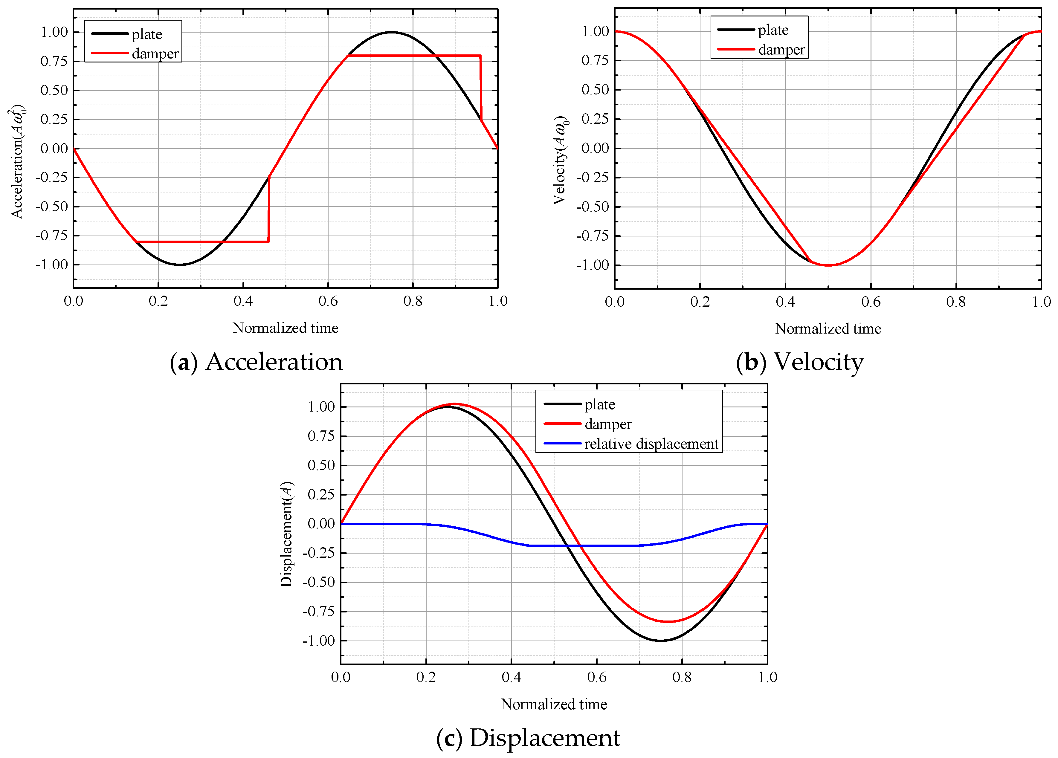
The axial displacement equation of the ring damper is z 1 ( θ , t ) , and the motion state of the ring damper is determined by the frictional force. The velocity and acceleration of the ring damper in the viscous state are the same as the velocity and acceleration of the gear damper groove position, which can be obtained by the axial displacement equation of the gear groove:
z ˙ 1 ( θ , t ) = z ˙ 0 ( θ , t ) = ω 0 A cos ( N θ ) cos ( ω 0 t ) z ¨ 1 ( θ , t ) = z ¨ 0 ( θ , t ) = ω 0 2 A cos ( N θ ) sin ( ω 0 t ) } t 0 ( θ ) < t < t 1 ( θ )
When the acceleration of the damper ring reaches the maximum acceleration provided by the friction force, the motion state becomes a slip:
sin [ ω 0 t 1 ( θ ) ] = k ( θ ) = μ Ω 2 r A ω 0 2 cos ( N θ )
where Ω is the angular velocity of gear, r is the radius of ring damper. Only when | k ( θ ) | < 1 , Equation (35) has a solution. | k ( θ ) | > 1 indicates that the maximum frictional force provided by the contact surface is greater than the frictional force required to maintain the synchronous movement of the ring damper and the gear. The ring damper is subjected to static friction and in a viscous state. t1 is a function of the circumferential position angle 
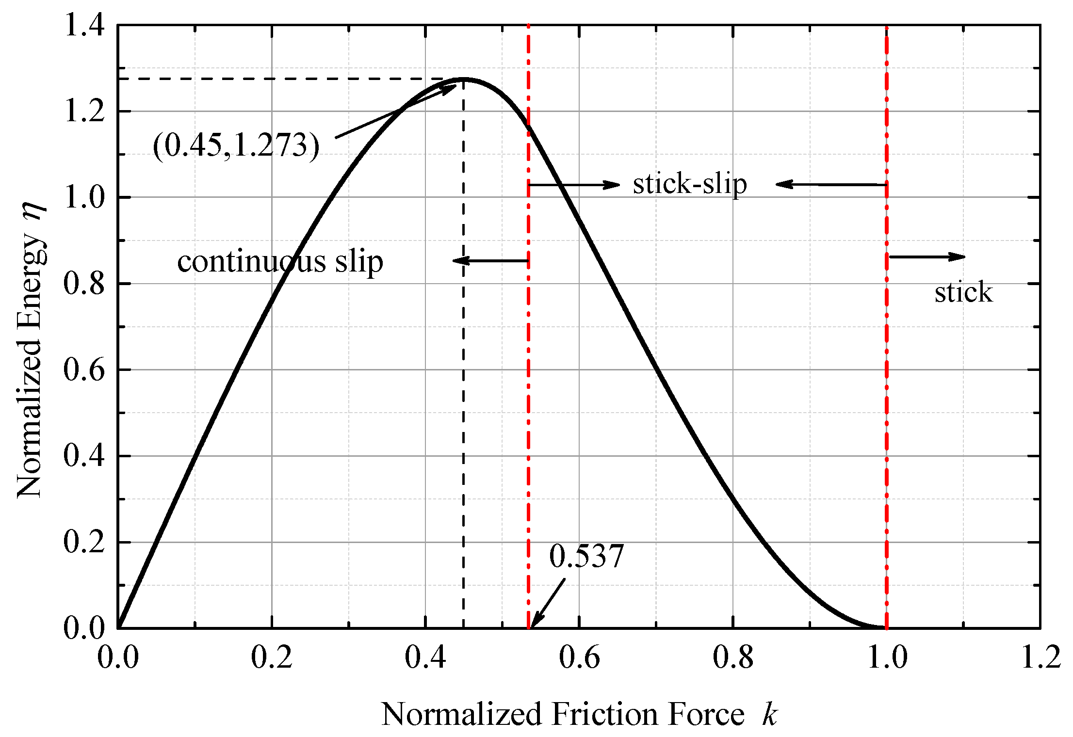
θ. Since the normalized frictional force of different circumferential positions of the ring damper is variable, the minimum normalized frictional force occurs at the maximum amplitude, defined as:
k ( θ ) | min = μ Ω 2 r A ω 0 2 = k 0
When the damping ring begins to slip, k0 = 1, thereby obtaining the critical amplitude under given conditions.
A | critical = μ Ω 2 r ω 0 2
When a slip occurs, the ring damper is subjected to a sliding frictional force, the acceleration is constant, and the velocity and acceleration equations are:
z ˙ 1 ( θ , t ) = ω 0 A cos ( N θ ) { ω 0 k ( θ ) [ t t 1 ( θ ) ] + cos [ ω 0 t 1 ( θ ) ] } z ¨ 1 ( θ , t ) = k ( θ ) ω 0 2 A cos ( N θ ) } t 1 ( θ ) < t < t 2 ( θ )
When the velocity of the ring damper is equal to the speed of the gear, the motion state will become viscous again, and z ˙ 1 ( θ , t 2 ( θ ) ) = z ˙ 0 ( θ , t 2 ( θ ) ) .
According to the above equation, the relationship between t 2 ( θ ) and t 1 ( θ ) can be obtained:
ω 0 k ( θ ) [ t 2 ( θ ) t 1 ( θ ) ] = [ cos ( ω 0 t 2 ( θ ) ) cos ( ω 0 t 1 ( θ ) ) ]
When the sliding frictional force is small, there is no viscous state in one vibration cycle, which is called a full sliding state. In this case, t 3 ( θ ) = t 2 ( θ ) , and:
t 1 ( θ ) = arc cos k ( θ ) π 2 ω 0 ,   t 3 ( θ ) = t 2 ( θ ) = t 1 ( θ ) + π ω 0 ,   t 4 ( θ ) = t 1 ( θ ) + 2 π ω 0
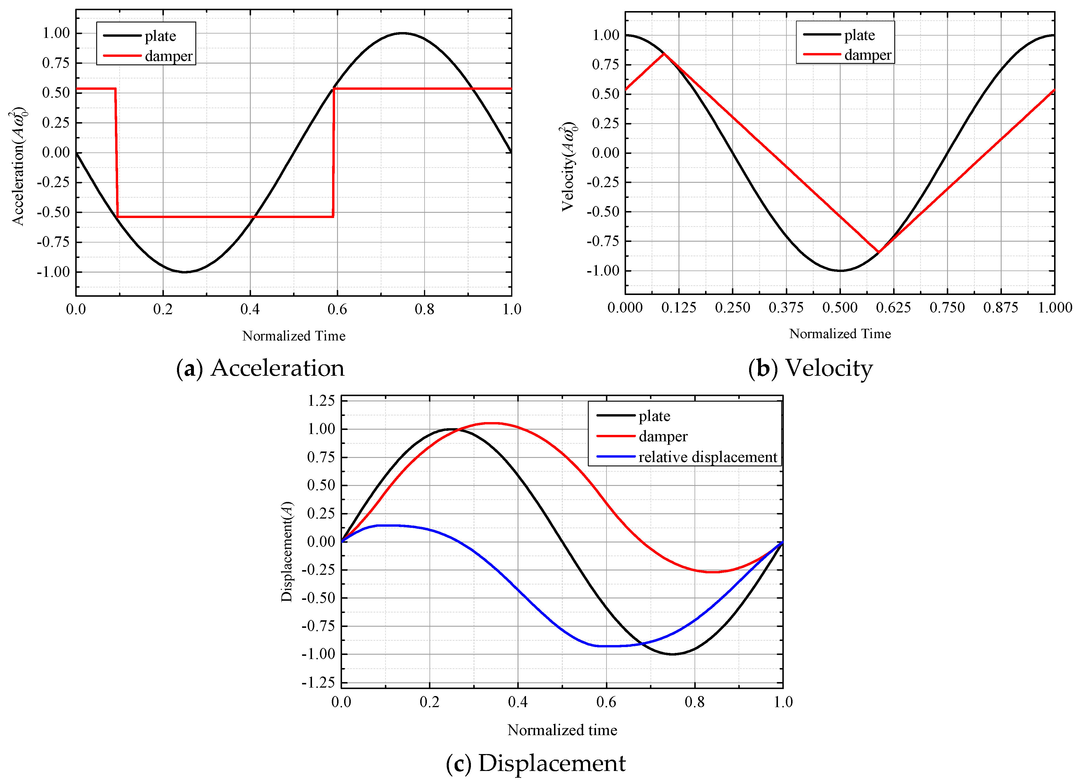
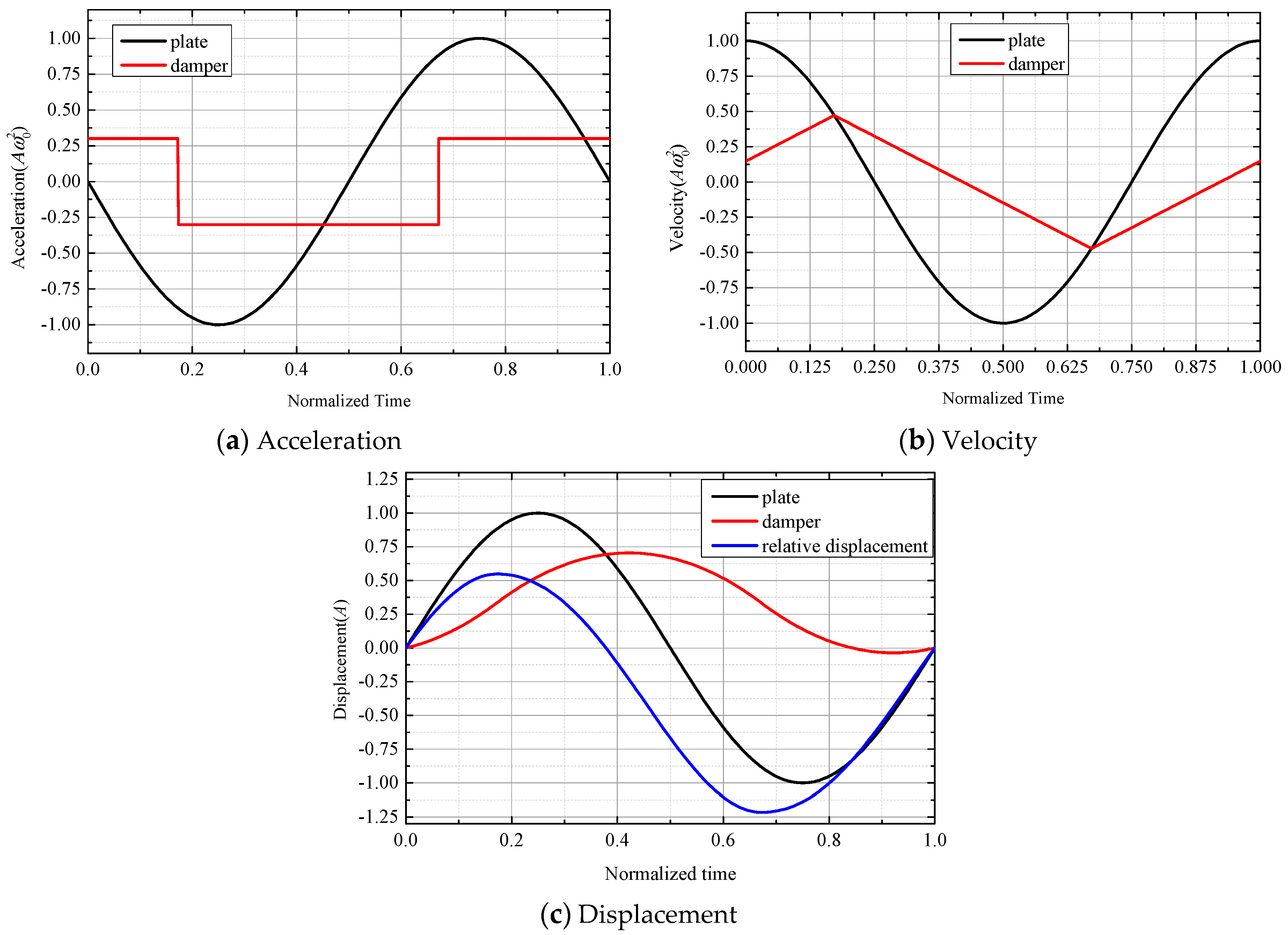
As the sliding frictional force increases, i.e., k ( θ ) gradually increases, there is an alternating slip and viscous in a vibration cycle, which is called a viscous-sliding state. In this case, the critical moment of the first slip zone and the viscous zone is obtained by Equation (35):
t 1 ( θ ) = arc sin k ( θ ) ω 0
t 2 ( θ ) can be obtained by Equations (39) and (42):
ω 0 k ( θ ) [ t 2 ( θ ) arc sin k ( θ ) ω 0 ] = [ cos ( ω 0 t 2 ( θ ) ) 1 k 2 ( θ ) ]
It should be noted that t 2 ( θ ) is a transcendental equation and requires numerical solution.
At the critical value of full sliding and viscous-sliding, the t 1 ( θ ) obtained by Equations (41) and (42) are equal, and further obtain:
k ( θ ) | critical = 1 1 + ( π / 2 ) 2 0.537
The relative displacement of the ring damper to the gear at circumferential position θ can be obtained by integration:
Δ s ( θ ) = 2 t 1 ( θ ) t 2 ( θ ) [ z ˙ 1 ( θ , t ) z ˙ 0 ( θ , t ) ] d t = 2 ω 0 A cos ( N θ ) t 1 ( θ ) t 2 ( θ ) [ ω 0 k ( θ ) ( t t 1 ( θ ) ) + cos ( ω 0 t 1 ( θ ) ) cos ( ω 0 t ) ] d t = 2 ω 0 A cos ( N θ ) { ω 0 k ( θ ) [ t 2 ( θ ) t 1 ( θ ) ] 2 + cos ( ω 0 t 1 ( θ ) ) [ t 2 ( θ ) t 1 ( θ ) ] 1 ω 0 [ sin ( ω 0 t 2 ( θ ) ) sin ( ω 0 t 1 ( θ ) ) ] }
The energy dissipated by the ring damper in one vibration cycle can be calculated by integrating the relative displacement of the circumferential points with the friction product:
Δ W = 0 2 π Δ s ( θ ) F f 2 π d θ = 4 N 0 π 2 N Δ s ( θ ) F f 2 π d θ = 4 N 0 arc cos k min N Δ s ( θ ) F f 2 π d θ
η = Δ W / ω 0 2 A 2 m r is defined as the normalized friction energy dissipation, and mr is the ring damper mass. The physical meaning of the normalized friction energy dissipation is the ratio of the friction energy dissipation to the maximum kinetic energy of the ring damper. Damping ratio can be expressed as:
ζ = Δ W 4 π W = Δ W 4 π ( M eq ω 0 2 A 2 + m r ω 0 2 A 2 ) = η m r 4 π ( M eq + m r )
where Meq is the equivalent mass of the gear in a given mode, relating to the vibration form and gear.
M eq = Φ Μ Φ T
where M represents the physical mass matrix of the gear and Φ represents the mode matrix.
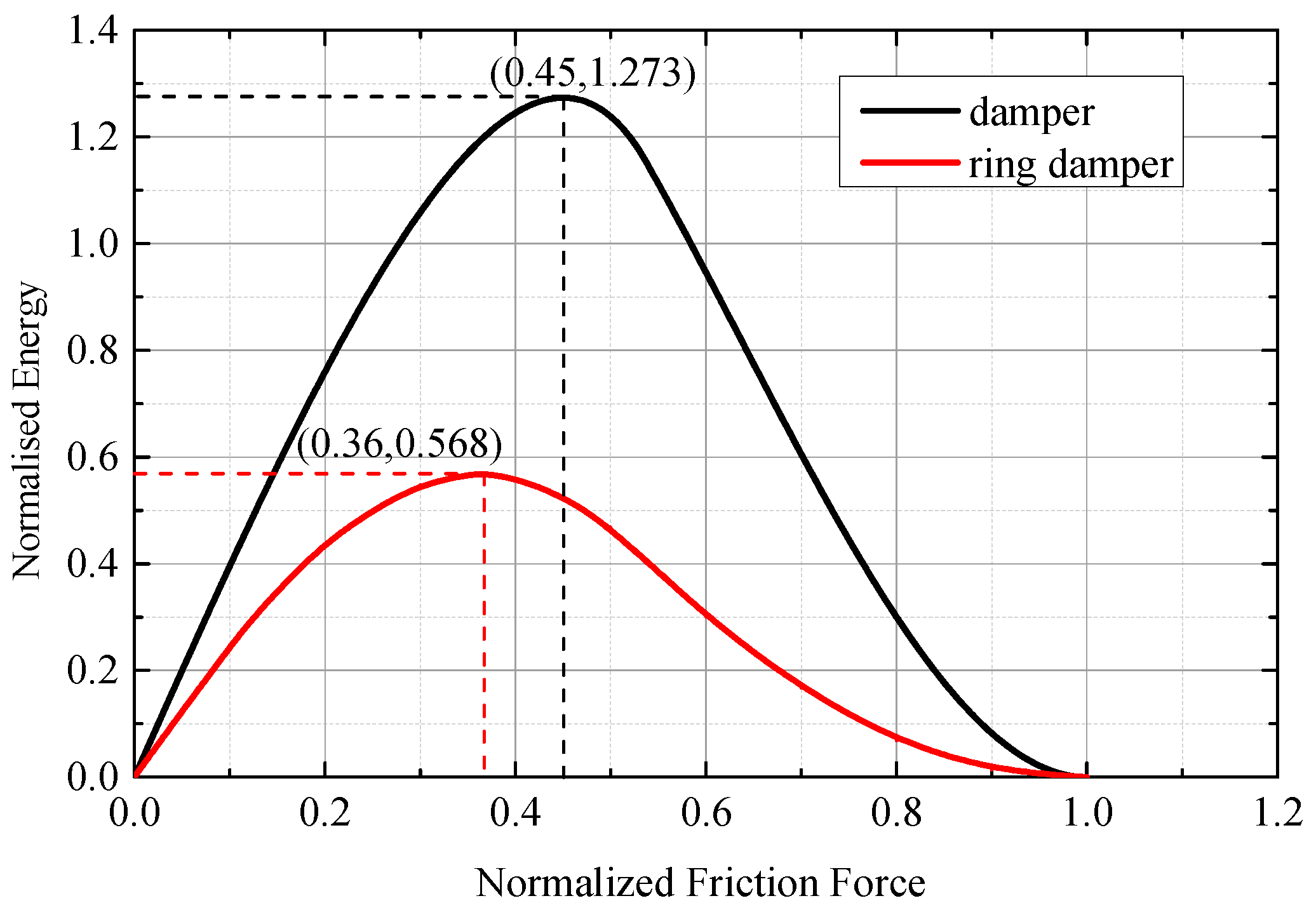
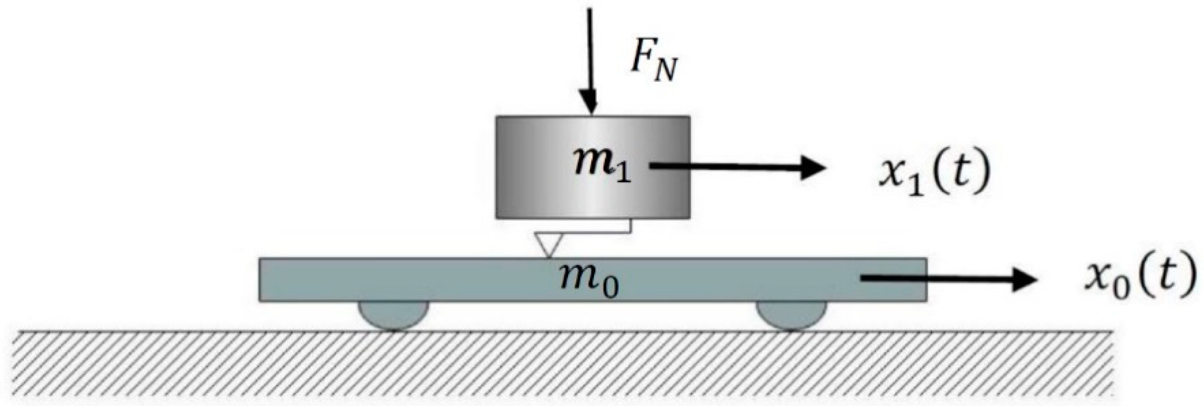
Figure 9 shows the relationship between the frictional force and the energy dissipation of the axial-vibration in the flat plate-slider model and ring damper-gear model. The energy dissipation of the flat plate-slider model was found to be greater. This is because the ring damper has a small amplitude near the nodal line under nodal diameter vibration, and its corresponding normalized frictional force is close to 1 or even greater than 1; thus, friction energy dissipation is little. The ring damper-gear model under axial vibration is similar to the flat plate-slider model, and there is a constant optimal normalized frictional force of approximately 0.365, which is smaller than the flat plate-slider model.
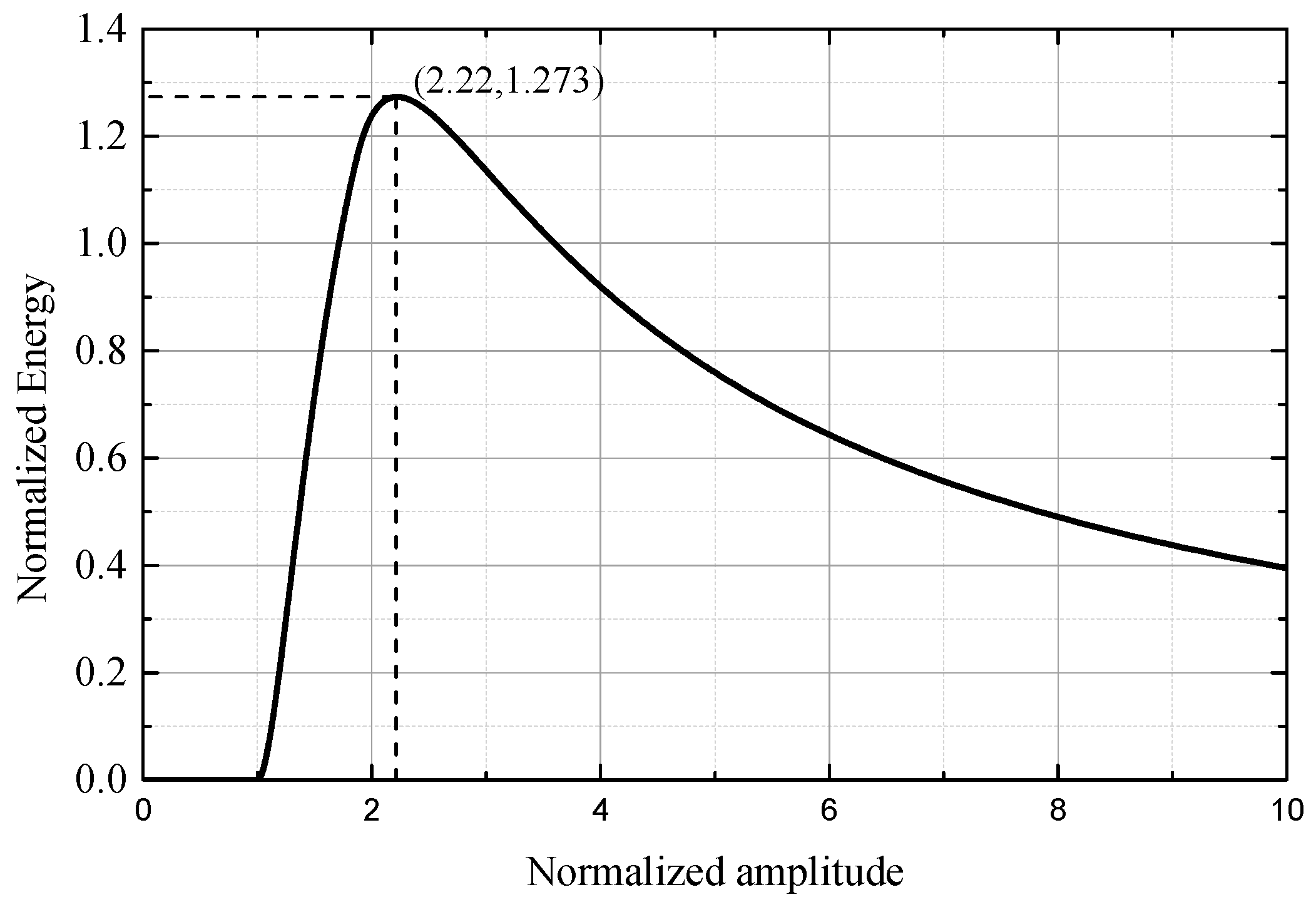
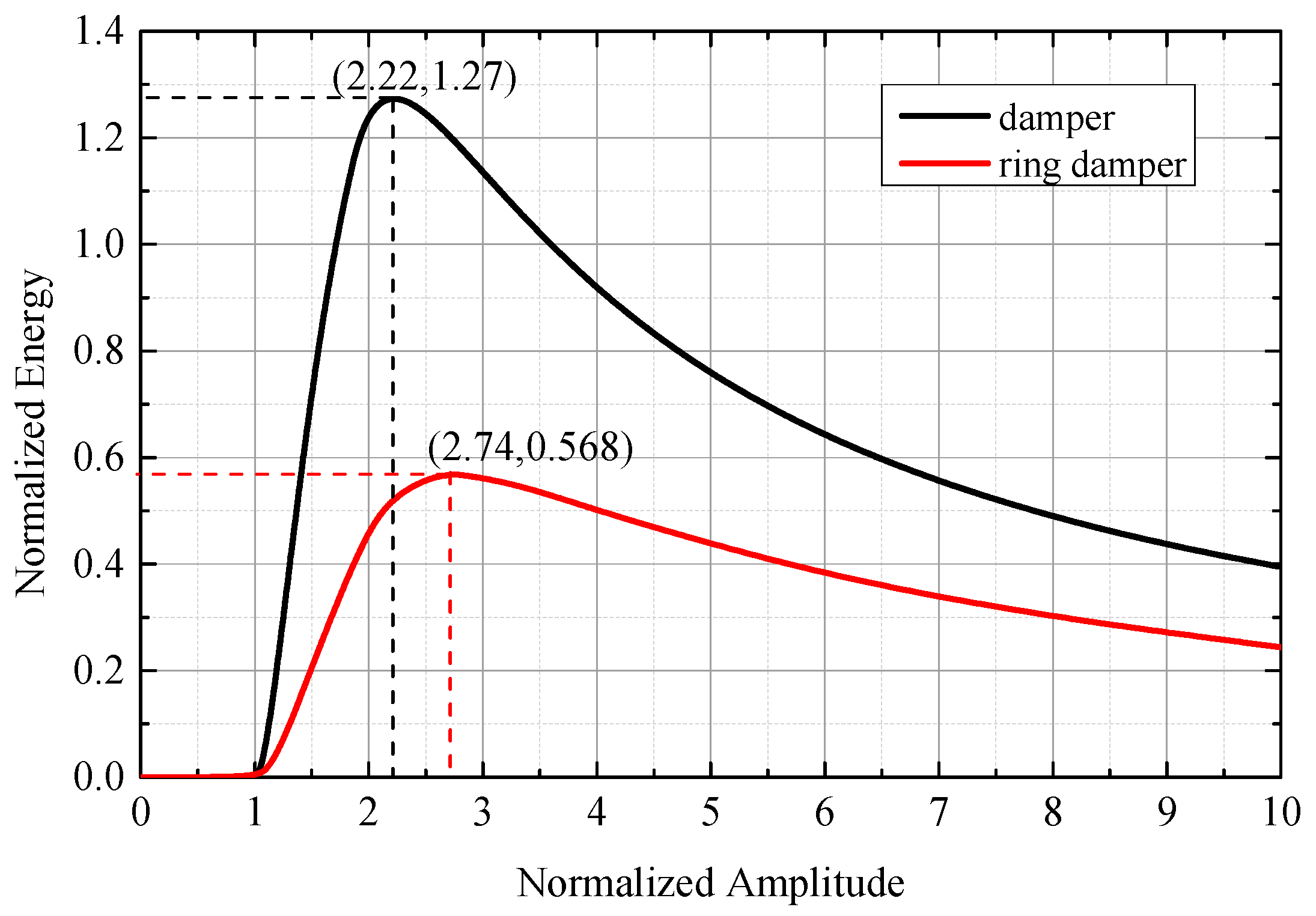
Figure 10 shows the relationship between the amplitude and energy dissipation of the axial vibration in the flat plate-slider model and the ring damper-gear model. The definition of normalized amplitude is the same as above. When the amplitude is small, the acceleration provided by the friction can maintain the non-slip motion between the damper and the main structure, so there is no friction energy dissipation. As the amplitude increases, there is a slip in the damper and the main structure. The friction energy dissipation increases rapidly with the increase of the amplitude. After peak energy dissipation, the increase of friction energy dissipation is smaller than the kinetic energy increase of the damper as the amplitude increases, and the normalized energy dissipation begins to decrease. The optimum amplitude of the flat plate-slider model appears at a critical amplitude of 2.22 times. The optimal amplitude of the ring damper under the nodal diameter axial vibration is about 2.74 times the critical amplitude.

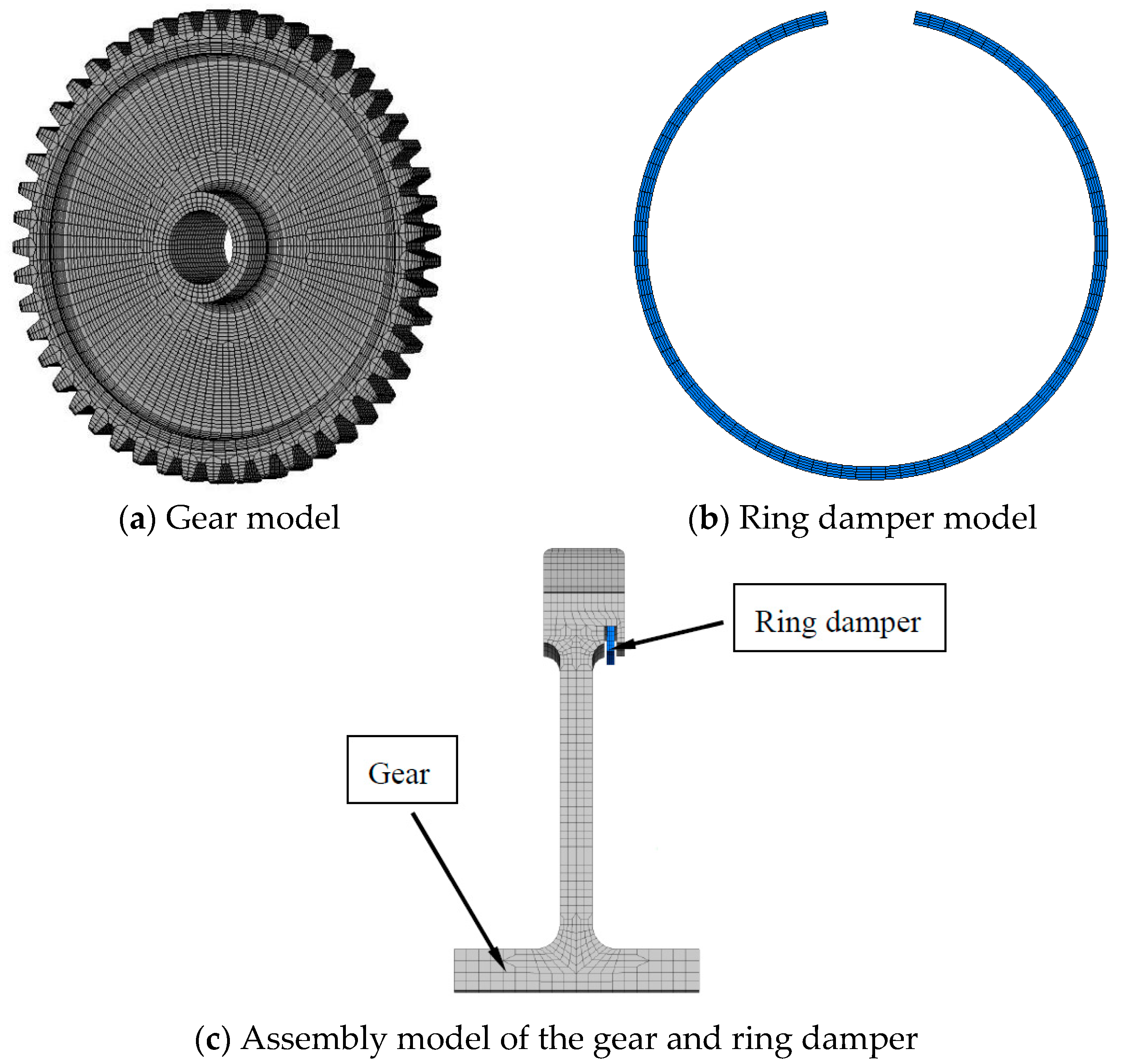
5. Effect of Ring Damper Parameters

In order to discuss the effect of mass and friction coefficient on equivalent damping, a gear model with the following parameters was used: steel, with a density of 7830 kg/m3, Poisson’s ratio of 0.3 and an elastic modulus of 210 Gpa (room temperature), as shown in 
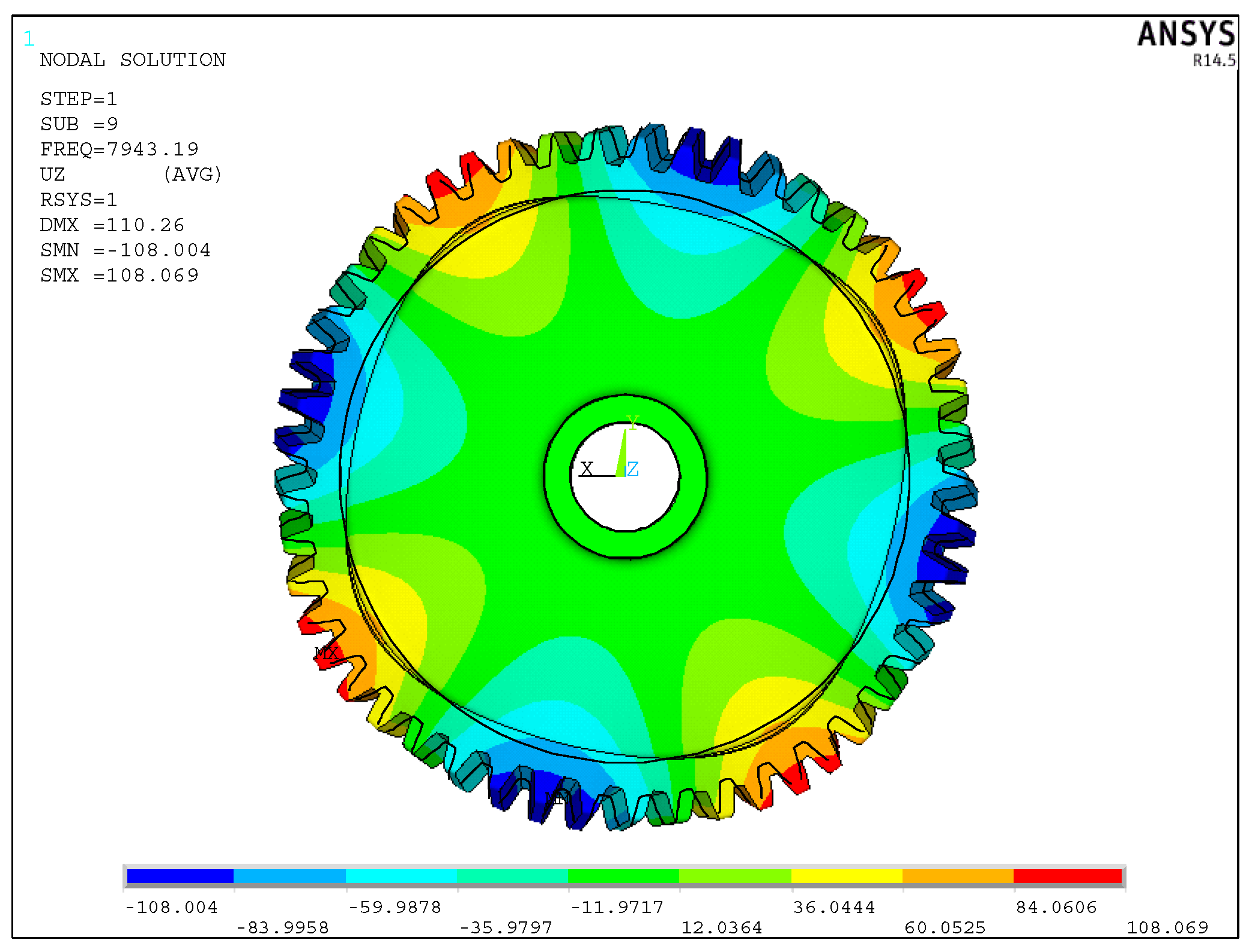
Figure 2a. According to the modal calculation, the gear has a 4 nodal diameter resonance at a working speed of 10,590 r/min; a vibration mode diagram is presented in Figure 11. Taking the 4 nodal diameter vibration of the gear as an example, the effect of mass on equivalent damping is shown in Figure 12, and the effect of friction coefficient on equivalent damping is shown in Figure 13.
Figure 12 shows the effect of the ring damper mass on the equivalent damping. Equation (46) shows that the equivalent damping ratio is positively correlated with its mass. When the ring damper mass is much smaller than the gear mass, the equivalent damping ratio of the ring damper under axial vibration is approximately linear. It can be seen from Equation (37) that the critical amplitude is independent of the mass of the ring damper because the frictional force and inertial force of the ring damper are both proportional to its mass, and the critical amplitude is related to the ratio of the frictional force and the inertial force. Therefore, in the computational model of this paper, the ring damper mass is linear with critical amplitude. Increasing the ring damper mass will be beneficial in increasing its equivalent damping.
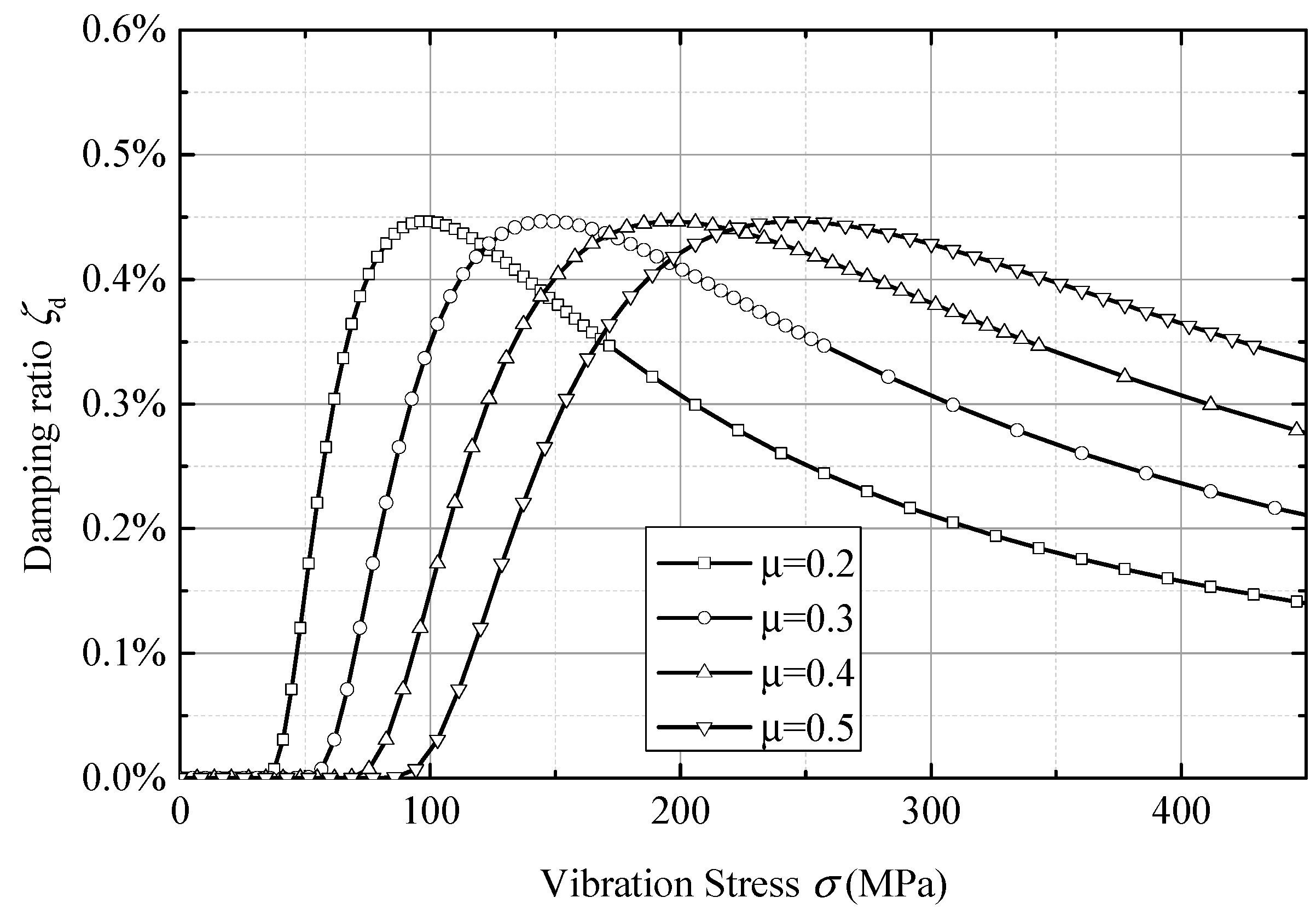
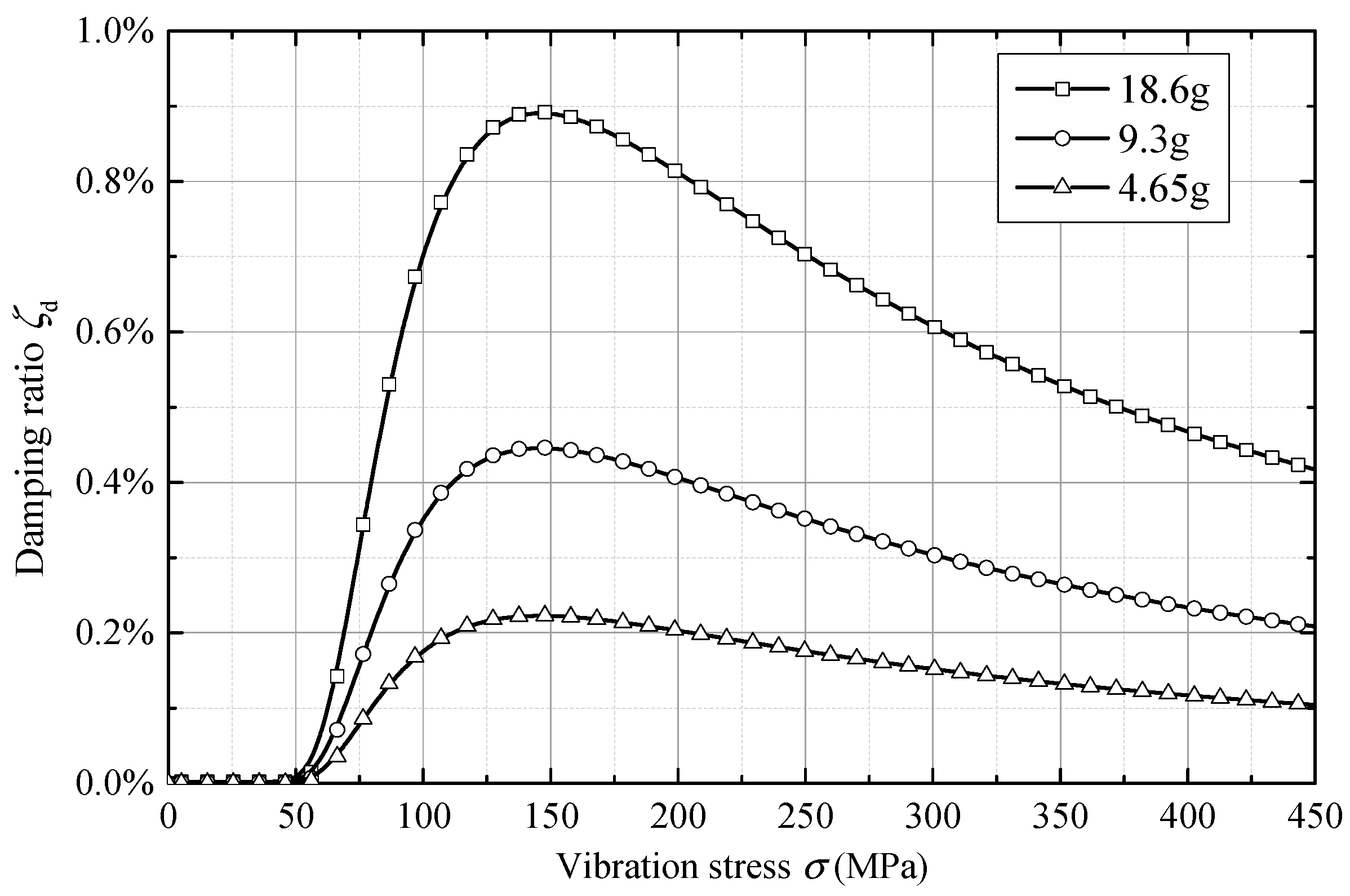
Figure 13 shows the effect of friction coefficient on equivalent damping. The friction coefficient is linear with the critical vibration loads, and does not affect the damping ratio peak. In the ring damper design, the critical vibration load must be less than the allowable vibration load, otherwise the ring damper will lose its damping effect; however, when the critical vibration load is too small, it may cause the ring damper to work on the right side of the damping peak. As can be seen from Figure 13, on the right side of the damping peak, the damping ratio decreases as the vibration loads increases. Thus, for a vibration state, there is an optimal friction coefficient provided by the ring damper.

6. Conclusions

In this paper, an equivalent damping numerical prediction method for a ring damper under axial vibration is proposed. The friction energy dissipation model due to inertia is established by using a flat plate-slider model, and its extension is applied to nodal diameter vibration. This model is used to analyze the influence of ring damper parameters on its equivalent damping. According to the analysis, the following conclusions can be drawn:
(1)
Under the axial component of the nodal diameter vibration, friction energy dissipation is caused by the relative motion between the gear and the ring damper.
(2)
In the flat plate-slider model, there is a critical amplitude that causes a relative motion between the slider and the plate. When the amplitude is greater than the critical amplitude, the friction energy dissipation increases with the amplitude. An optimum amplitude maximizes the equivalent damping provided by the slider, and the optimum amplitude is π / 2 times of the critical amplitude.
(3)
For any given model, there is a critical vibration load. When the vibration load does not reach the critical value, the ring damper gets stuck in the gear, and there is no damping effect. When the vibration load is greater than the critical vibration load, the contact surface of the gear and the ring damper slide relative to each other, and the vibration energy is dissipated by the frictional force, thus enabling the ring damper to work. The optimal amplitude is 2.74 times that of the critical amplitude.
(4)
When the ring damper mass is much smaller than the gear mass, the equivalent damping provided by the ring damper is proportional to its mass.
(5)
When other parameters are constant, the friction coefficient is linear with the critical vibration load, but does not affect the peak damping.

Author Contributions

Conceptualization, S.W. and X.W.; Data curation, H.Y.; Methodology, S.W. and Y.W.; Software, S.W. and H.Y.; Writing – original draft, S.W.

Funding

This research received no external funding.

Conflicts of Interest

The authors declare no conflicts of interest.

Notation

uVibration displacement
CDamping matrix
F ext External exciting force
C eq Equivalent damping
ΦGear system modal matrix
ζ Damping ratio of the gear
β Damping ring mass rate
m g Mass of the gear
αProportional coefficient
FNNormal force
ω0Circular vibration frequency of plate
kNormalized frictional parameter
ηNormalized friction energy dissipation
θCircumferential position
Ω Angular velocity of gear
r Radius of ring damper
MMass matrix
KStiffness matrix of the gear system
F nl Nonlinear friction force
K eq Equivalent stiffness
qModal displacement vector
ζ eq Equivalent damping ratio
m d Mass of the ring damper
σVibration loads
m1Mass of the slider
AAmplitude of structure
x ( t ) Displacement of slider
F f Maximum static friction force
Δ W Dissipated energy of any period in the steady state
z ( θ , t ) Axial displacement of ring damper
μ Friction coefficient
Δ s ( θ ) Relative displacement of the ring damper to the gear

References

  1. Mclntire, W.L. How to Reduce Gear Vibration Failures; AGMA Aerospace Gearing Committee Meeting; American Gear Manufacturers Association: Orlando, FL, USA, 1964. [Google Scholar]
  2. Drago, R.J.; Brown, F.W. The analytical and experimental evaluation of resonant response in high-speed, lightweight, highly loaded gearing. J. Mech. Des. 1981, 103, 346–356. [Google Scholar] [CrossRef]
  3. Laxalde, D.; Thouverez, F.; Sinou, J.J.; Lombard, J.P. Qualitative analysis of forced response of blisks with friction ring dampers. Eur. J. Mech. A/Solids 2007, 26, 676–687. [Google Scholar] [CrossRef]
  4. Laxalde, D.; Thouverez, F.; Lombard, J.P. Forced response analysis of integrally bladed disks with friction ring dampers. J. Vib. Acoust. 2010, 132, 011013. [Google Scholar] [CrossRef]
  5. Zucca, S.; Firrone, C.M.; Facchini, M. A method for the design of ring dampers for gears in aeronautical applications. J. Mech. Des. 2012, 134, 091003. [Google Scholar] [CrossRef]
  6. Firrone, C.M.; Zucca, S. Passive control of vibration of thin-walled gears: Advanced modelling of ring dampers. Nonlinear Dyn. 2014, 76, 263–280. [Google Scholar] [CrossRef]
  7. Baek, S.; Epureanu, B. Reduced-order modeling of bladed disks with friction ring dampers. J. Vib. Acoust. 2017, 139, 061011. [Google Scholar] [CrossRef]
  8. Tang, W.; Baek, S.; Epureanu, B.I. Reduced-order models for blisks with small and large mistuning and friction dampers. J. Eng. Gas Turbines Power 2017, 139, 012507. [Google Scholar] [CrossRef]
  9. Tang, W.; Epureanu, B.I. Nonlinear dynamics of mistuned bladed disks with ring dampers. Int. J. Non-Linear Mech. 2017, 97, 30–40. [Google Scholar] [CrossRef]
  10. Tang, W.; Epureanu, B.I. Geometric optimization of dry friction ring dampers. Int. J. Non-Linear Mech. 2019, 109, 40–49. [Google Scholar] [CrossRef]
  11. Lopez, I.; Busturia, J.M.; Nijmeijer, H. Energy dissipation of a friction damper. J. Sound Vib. 2004, 278, 539–561. [Google Scholar] [CrossRef]
  12. Lopez, I.; Nijmeijer, H. Prediction and validation of the energy dissipation of a friction damper. J. Sound Vib. 2009, 328, 396–410. [Google Scholar] [CrossRef]
  13. Ziegert, J.C. Optimal design of split ring dampers for gas turbine engines. J. Eng. Gas Turbines Power 1995, 117, 569. [Google Scholar]
  14. Lopez, I. Theoretical and Experimental Analysis of Ring-Damped Railway Wheels. Ph.D. Thesis, Universidad de Navarra, Pamplona, Spain, November 1998. [Google Scholar]
  15. Tangpong, X.W.; Wickert, J.A.; Akay, A. Finite element model for hysteretic friction damping of traveling wave vibration in axisymmetric structures. J. Vib. Acoust. 2008, 130, 011005. [Google Scholar] [CrossRef]
  16. Tangpong, X.W.; Wickert, J.A.; Akay, A. Distributed friction damping of travelling wave vibration in rods. Philos. Trans. R. Soc. Lond. A Math. Phys. Eng. Sci. 2008, 366, 811–827. [Google Scholar] [CrossRef] [PubMed]
Figure 1. Transmission system and accessories in an aircraft gas turbine engine.
Symmetry 11 01469 g001
Figure 2. Ring damper shape and a typical gear–ring damper system.
Symmetry 11 01469 g002
Figure 3. Flat plate-slider system.
Symmetry 11 01469 g003
Figure 4. Velocity and displacement of the slider and plate in a viscous-sliding state (k = 0.8).
Symmetry 11 01469 g004
Figure 5. Acceleration, velocity, and displacement of slider and plate in critical state (k = 0.537).
Symmetry 11 01469 g005
Figure 6. Velocity and displacement of the slider and the plate in full sliding state (k = 0.3).
Symmetry 11 01469 g006
Figure 7. Relationship between normalized frictional force and normalized energy dissipation.
Symmetry 11 01469 g007
Figure 8. Relationship between normalized energy dissipation and normalized amplitude.
Symmetry 11 01469 g008
Figure 9. The relationship between the minimum normalized frictional force and the normalized energy dissipation of the slider (black line) and the ring damper (red line).
Symmetry 11 01469 g009
Figure 10. The relationship between the normalized amplitude and the normalized energy dissipation of the slider (black line) and the ring damper (red line).
Symmetry 11 01469 g010
Figure 11. 4 nodal diameter vibration mode.
Symmetry 11 01469 g011
Figure 12. Effect of the ring damper mass on equivalent damping.
Symmetry 11 01469 g012
Figure 13. Effect of friction coefficient on equivalent damping.
Symmetry 11 01469 g013

