Article

A Computationally Efficient Joint Cell Search and Frequency Synchronization Scheme for LTE Machine-Type Communications

Department of Computer Engineering, Sejong University, Gwangjin-gu, Gunja-dong 98, Seoul 05006, Korea
*
Author to whom correspondence should be addressed.
Symmetry 2019, 11(11), 1394; https://doi.org/10.3390/sym11111394
Submission received: 18 October 2019 / Revised: 5 November 2019 / Accepted: 8 November 2019 / Published: 11 November 2019

Abstract

:
The key features for future machine-type communication cellular systems facilitate low-power, low-cost, narrow-band, and wide-area systems. One of the challenging tasks to realize these requirements in machine-type communication cellular networks is a low-cost initial synchronization. To address this issue, this paper presents a reduced-complexity joint estimation of integer carrier frequency offset and cell identity for machine-type communication in the long-term evolution system. Using the conjugate property of a primary synchronization signal, joint search space of a number of hypotheses is reduced by two-thirds, facilitating low-complexity detection. The performance is assessed in terms of theoretical probability of detection failure. Simulation results confirm that the proposed estimation scheme achieves approximately the same performance as the conventional scheme with notably low complexity.

1. Introduction

To ensure realization of machine-to-machine communications, the third generation partnership project proposed enhanced long-term evolution machine-type communication (LTE-MTC), extended coverage-global system for mobile communications for the Internet of Things (EC GSM-IoT), and narrow-band IoT (NB-IoT) as cellular-based low-power wide area (LPWA) schemes for the IoT [1,2,3]. Among them, MTC introduces a set of physical layer functions targeting supporting the wide coverage, big network, and low power consumption of user equipment (UE). Due to the limited transmission power, however, the MTC UE cannot arbitrarily increase its power to reach the enhanced base station (eNodeB). In particular, MTC devices in low mobility are usually encountered with deep coverage holes, leading to poor operating signal-to-noise ratio (SNR) [4]. Therefore, a main challenging issue in MTC is to provide coverage enhancement (CE) to enhance battery life and improve the performance of MTC units suffering from poor coverage problems [5]. A variety of techniqUE such as symbol repetition, frequency hopping, and reference-signal boosting have been suggested to improve detection ability of MTC UE in a poor coverage area [6,7]. Since narrow bandwidth and single-antenna configuration are adopted in LTE-MTC, either frequential or spacial diversity cannot be used. For this reason, frequency hopping is a new added feature to improve the performance of MTC UE within the reduced bandwidth [6]. To further support CE, subframe repetition over time is introduced in LTE-MTC. Using a repetition mechanism, the effect of time diversity can favorably enhance the capacity of the LTE-MTC network. However, such a repetition increases latency and wake-up time of MTC UE [7].
To shorten the stand-by time of the MTC UE, a discontinuous reception (DRX) scheme is used in the LTE-MTC system [8]. An MTC UE equipped with a DRX cycle wakes up only during its paging occasion to monitor paging messages from eNodeB, while it sleeps at other time periods, which facilitates the UE to sleep for very long periods of time. The prolonged sleep duration between events causes the local oscillator to deviate from its original operating frequency [9]. Since the receiver may lose its synchronization while switching off parts of the circuitry, it is necessary for the MTC receiver to wake up periodically at a specific time to achieve synchronization and cell identification. Because of the vulnerability of orthogonal frequency division multiplexing (OFDM) to synchronization imperfections, a reduced-cost synchronization scheme is necessary for the MTC device to shorten the search period, thus extending sleeping duration. Before connecting with the eNodeB, the MTC UE attempts to acquire synchronization looking for the position of the maximum correlation of the cyclic prefix (CP) [10] and identifying the synchronization signals, called the primary synchronization signal (PSS) and secondary synchronization signal (SSS) [11,12,13]. The PSS carries the information of sector ID (SID), whereas the SSS is transmitted to deliver the information about group ID (GID) and is also used to determine 10 ms radio frame boundary. Since the MTC UE can complete SSS detection only after the SID is correctly retrieved, the accurate identification of the PSS plays an important role in overall cell search procedure [9].
There exist some studies focusing on the PSS detection [13,14,15,16,17,18]. Some of these methods perform in the time domain [13,14], while the others use frequency-domain samples obtained from a discrete Fourier transform (DFT) unit [15,16,17,18]. In [14], the PSS detection method was proposed to be performed by finding the maximum of the cross-correlation in the time domain, wherein the integer carrier frequency offset (IFO) degrades the accuracy of detecting the PSS. To overcome this limitation, several differential correlation based PSS detection schemes have been presented using the frequency-domain PSS [15], wherein the IFO is estimated in parallel with the search process of PSS. As for the IFO, it can be detected in a joint or sequential way. The works in [15,16] estimate the IFO jointly during the PSS-matching process, which is accomplished performing the frequency-domain shift of the received PSS. Although the maximum likelihood (ML) estimator can achieve optimal performance in detecting the IFO [17], the complexity in realizing the ML solution is prohibitively high. The differential correlation based methods with reduced complexity were proposed in [18], wherein the IFO detection and SID recovery are performed in a decoupled manner using the central-symmetric nature of the PSS. Such a design can divide joint search space of a number of hypotheses into two reduced search spaces, while its performance is vulnerable to residual STO. The synchronization task is one of the most complex parts of the baseband processing load in a typical LTE-A device [19]. Specifically, the LTE-MTC introduces new challenging tasks to the system such as narrow-band operation, low-cost operation, and CE. To satisfy these requirements, existing cell search and initial synchronization schemes have to be modified [9]. Thus, it is crucial to develop a reduced-complexity cell search method that can minimize the processing power of the MTC UE during the initial cell search process.
To address this issue, a reduced-complexity joint cell search and frequency detection scheme are proposed for MTC over the LTE network. The conjugate property of the PSS sequence facilitates reducing joint search space to a small number of hypotheses. In the proposed method, a combination of the conjugate property and average estimate over multiple subframes achieves enhanced joint IFO and SID detection for the MTC UE in poor coverage conditions. It is demonstrated via simulation results that the proposed scheme performs initial cell search with significantly lower computational complexity while having almost similar detection performance to the existing estimation method.
The reminder of the paper is organized as follows. Section 2 presents the signal model in the LTE-MTC system. The existing joint estimation schemes adopting differential correlation are introduced in Section 3. In Section 4, the proposed joint estimation method is presented for LTE-MTC, and its performance is analyzed. The usefulness of the proposed method is verified via computer simulations in Section 5, and a conclusion is given in the last section.
The notations used in this paper are listed as follows: ( · ) * , | · | , ( · ) I , and ( · ) Q denote the operations taking the complex conjugation, absolute value, real part, and imaginary part of the enclosed complex quantity, respectively. The notation M N ( μ , σ 2 ) means that M is a Gaussian random variable (RV) with mean μ and variance σ 2 .

2. System Description

In this section, the frame structure, cell search process, synchronization signal, and signal model for LTE-MTC will be explained.

2.1. Frame Structure

LTE supports both frequency division duplex (FDD) and time division duplex (TDD) modes. Figure 1 shows the FDD downlink frame structure in the LTE system. The reference signal (RS) is a crucial signal that is used for channel estimation and data demodulation. In an LTE system, the PSS and SSS are located in subframes 0 and 5, which are used by the UE to obtain the cell ID (CID) and synchronization. The physical downlink control channel (PDCCH) is used to carry scheduling assignments and other control information. A PDCCH is transmitted on an aggregation of one or several consecutive control channel elements (CCEs). The physical downlink shared channel (PDSCH) is a physical channel that carries user data. The physical broadcast channel (PBCH) is used to carry the master information block (MIB).

2.2. Cell Search Procedure

At the beginning of communication, the MTC UE has to search for a best serving eNodeB by retrieving the CID and accurate initial synchronization [9,10,11,12], which is known as initial cell search. Due to the vulnerability of OFDM to time-frequency misalignments, symbol timing offset (STO) and carrier frequency offset (CFO) are usually estimated during the cell search procedure. To assist these operations, the PSS and SSS sequences are transmitted periodically from the eNodeB. Figure 2 shows the initial cell search procedure. The initial cell search procedure can be typically divided into three phases. Firstly, initial STO and fractional CFO (FFO) are estimated in the time domain by using redundant information present in the CP of the OFDM symbol [9,10]. Once the FFO is compensated and the CP type is identified, the DFT unit is used to transform the received time-domain samples into the frequency domain. Upon the successful completion of this step, the IFO detection can be performed together with the search process of PSS, which may be accomplished either in the time or frequency domain [11]. Finally, the detection of the GID and the acquisition of frame boundary are performed by analyzing the received SSS [12,13], thus resolving 10 ms radio frame timing. Once these operations have been finished, the MTC UE tries to detect broadcast data channel information checking the successful completion of initial cell search. If the CID is erroneously identified, it is useless to decode the MIB and SIB. Therefore, the CID detection is one of the most challenging tasks during overall cell search procedure.

2.3. Synchronization Signal

In LTE-MTC, PSS, and SSS sequences are two synchronization signals that introduce 504 distinct CIDs. The CIDs are divided into 168 unique GIDs, which are indexed as N I D ( 1 ) { 0 , 1 , , 167 } . Each group contains three SIDs in a cell, which are indexed as N I D ( 2 ) { 0 , 1 , 2 } . A physical layer CID can thus be represented uniquely by N I D = N I D ( 2 ) + 3 N I D ( 1 ) . To camp on a cell successfully, MTC UE must acquire the integer-valued information N I D ( 1 ) and N I D ( 2 ) using the SSS and PSS sequences, respectively. In the frequency domain, the PSS and SSS sequences are transmitted twice per 10 ms radio frame in the central six resource blocks (RBs). Let N p denote the number of the subcarriers of PSS or SSS excluding null subcarriers. The synchronization signals use N p = 62 subcarriers in total, with N p / 2 subcarriers assigned on each side of the DC subcarrier. The PSS is on the basis of the frequency-domain length-63 Zadoff–Chu (ZC) sequence with zero punctuation at the DC subcarrier component [20]. Three PSS sequences with the root indices { z 0 , z 1 , z 2 } = { 25 , 29 , 34 } are selected to carry the SID information
P i ( k ) = e j π z i ( k 2 + 992 ) / 63 j π z i k , k P , 0 , otherwise ,
where P = { k | N p / 2 k N p / 2 , k 0 } . As can be seen from Equation (1), P i ( k ) = P i ( k ) for k P and all i’s.
The main purpose of the SSS is to recognize the GID and to find the starting position of an LTE frame. The SSS sequence forms binary phase-shift keying (BPSK) signal S ( k ) , which is derived from two length-31 scrambled and cyclically shifted binary sequences [1]. The position of the SSS in LTE frame depends on the duplex mode. In FDD mode, as depicted in Figure 1, the PSS is present in the last symbol of the first slot of subframe of 0 and 5, whereas the SSS is located just prior to the PSS.

2.4. Signal Model

Consider an OFDM system employing N-point DFT and CP with a length of N g . After taking an N-point inverse DFT (IDFT) on complex symbols, the output of IDFT is the baseband OFDM symbol block x q ( u ) , u = 0 , 1 , , N 1 . In the beginning of OFDM symbol block, a CP is added which is a copy of the last N g samples, generating one effective OFDM symbol x q ( u ) , u = N g , N g + 1 , , N 1 . Thus, the u-th time-domain sample during the q-th period x q ( u ) can be represented by
x q ( u ) = k S X q ( k ) e j 2 π k u / N ,
where X q ( k ) denotes the signal at the k-th subcarrier over the q-th duration and S = { k | N / 2 k < N / 2 } . Thus, the total duration of one OFDM symbol is ( N + N g ) T s with T s being the sampling time of any OFDM signal block. Since the PSS is present twice per frame, the observation window for PSS detection includes N o adjacent OFDM symbols that compose a half frame, where N o is either 60 or 70 depending on the extended or normal CP mode, respectively. For notational simplicity, we consider the situation where the PSS is transmitted on the l-th OFDM symbol within the observation window q = 1 , 2 , , N o , namely, X l ( k ) = P i ( k ) . Since the location of the SSS sequence differs from duplex mode, it follows that X l 1 ( k ) = S ( k ) for FDD mode, while X l 3 ( k ) = S ( k ) for TDD mode.
The signals transmitted from the eNodeB are passed through the multipath fading channel with additive white Gaussian noise (AWGN). It is assumed that the maximum delay spread of the multipath channel does not exceed the CP interval. At the MTC UE terminal, the received signal is down-converted to baseband and sampled with duration of T s . Because the FFO and STO marginally affect the accuracy of existing IFO detection schemes proposed in [16,17], it is assumed that the FFO and STO are perfectly known at MTC UE. Accordingly, the time-domain sample during the q-th period y q ( u ) can be given as [14]
y q ( u ) = e j q υ N g ρ e j υ u ρ p = 1 L h q ( p ) x q ( u p ) + w q ( u ) , | υ | M ,
where ρ = 2 π / N , υ represents the IFO normalized by subcarrier spacing Δ f = 1 / N T s , h q ( p ) is the channel impulse response with L resolvable paths, M is the finite number of possibilities of υ , and w q ( u ) denotes a zero-mean AWGN. After FFO recovery and CP removal, the DFT unit is used to produce the frequency-domain version of y q ( u ) , which is written by [17]
Y q ( k ) = H q ( k υ ) X q ( k υ ) e j q υ N g ρ + W q ( k ) , k S ,
where H q ( k ) is the DFT of h q ( p ) and W q ( k ) is the DFT of w q ( u ) with variance σ W 2 .

3. Conventional Detection Scheme

This section gives a brief review of existing detection schemes. For notation convenience, the PSS is considered to be present in the l-th OFDM symbol with energy E P = | P i ( k ) | 2 , namely, X l ( k ) = P i ( k ) . To perform robust estimation in the presence of STO and fading distortion, differential correlation between nearby subcarriers of the received PSS is used to form
Y ¯ l ( k ) = Y l ( k ) Y l * ( k 1 ) | H l ( k υ ) | 2 D i ( k υ ) + W ¯ l ( k ) , k D ,
where D = { k | N p / 2 + 1 k 1 , 2 k N p / 2 } whose cardinality is N p 2 , D i ( k ) = P i ( k ) P i * ( k 1 ) denotes the complex conjugate relation between two neighboring PSS subcarriers, and W ¯ l ( k ) denotes the contribution to AWGN written by
W ¯ l ( k ) = H l ( k υ ) X l ( k υ ) W l * ( k 1 ) e j l υ N g ρ + H l * ( k υ 1 ) X l * ( k υ 1 ) W l ( k ) e j l υ N g ρ + W l ( k ) W l * ( k 1 ) .

3.1. Half-Complexity Joint Detection (HCJD) Scheme

A low-complexity estimation scheme exploiting inherent central-symmetric feature of the ZC sequences is commonly utilized in the LTE-MTC system [15,16,17]. In this approach, the metric is defined as the correlation from the symmetric-conjugate differential PSS and local differential reference PSS
Φ a ( m , n ) = k D + Y ¯ l ( k + m ) + Y ¯ l * ( k + m + 1 ) D n * ( k ) ,
where m refers to the trial value of a true IFO, D + = { k | 2 k N p / 2 } whose cardinality is N p / 2 1 , and Φ a ( m , n ) represents the joint metric of the HCJD scheme. The objective is to find the joint estimate of the IFO and SID by maximizing Φ a ( m , n ) with respect to two-dimensional search space ( m , n ) [17]
( υ ^ , n ^ ) = arg max | m | M , n { 0 , 1 , 2 } Φ a I ( m , n ) ,
with
Φ a I ( m , n ) = k D + Y ^ l I ( k + m ) D n I ( k ) + k D + Y ^ l Q ( k + m ) D n Q ( k ) ,
where Y ^ l ( k + m ) = Y ¯ l ( k + m ) + Y ¯ l * ( k + m + 1 ) , and ( · ) I and ( · ) Q denote the operation taking the real and imaginary part of the enclosed complex quantity, respectively.

3.2. Reduced-Complexity Sequential Detection (RCSD) Scheme

Based on the symmetric property of the PSS, a sequential IFO and SID detection algorithm is presented in [18]. To mitigate the effect of the fading distortion, the channel-compensated metric is computed using normalized PSS [18]
Φ b ( m ) = 1 N p / 2 1 k D + Y ˜ l ( k + m ) Y ˜ l ( k + m + 1 ) ,
where Y ˜ l ( k ) = Y ¯ l ( k ) / | Y ¯ l ( k ) | and Φ b ( m ) represent the metric to obtain the IFO in the RCSD scheme. The estimated IFO υ ^ is considered as the argument m that minimizes the cost function | Φ b ( m ) 1 |
υ ^ = arg   min | m | M Φ b ( m ) 1 .
The SID detection is sequentially performed with one-dimensional, search space
n ^ = arg   max n { 0 , 1 , 2 } Φ c I ( n ) ,
where Φ c ( n ) means the metric to obtain the SID in the RCSD scheme given by
Φ c ( n ) = k D + { Y ˜ l ( k + υ ^ ) + Y ˜ l * ( k + υ ^ + 1 ) } D n * ( k ) .

4. Proposed Detection Scheme

This section proposes a complexity-effective joint estimation method employing an inherent conjugate property of the synchronization signal to improve the detection performance in the LTE-MTC system. As a performance measure, the probability of detection failure and the computational burden of the proposed scheme are analyzed to assess the performance gain.

4.1. Algorithm Description

From the fact that P 1 ( k ) = P 2 * ( k ) , it follows that D 1 ( k ) = D 2 * ( k ) . This property yields Equation (9) in the form
Φ a I ( m , n ) = k D + Y ^ l I ( k + m ) D 1 I ( k ) + ( 1 ) n + 1 k D + Y ^ l Q ( k + m ) D 1 Q ( k ) , n = 1 , 2 ,
which indicates that the ambiguity associated with two ZC root indices z 1 and z 2 is only the polarity in the second term of the right-hand side (RHS). Therefore, the metrics for z 1 and z 2 are based on the same observation. Leveraging the above property, a reduced search space based metric is given by
Φ d ( m , n ) = k D + Y ^ l I ( k + m ) D n I ( k ) + k D + Y ^ l Q ( k + m ) D n Q ( k ) , n = 0 , 1 ,
where the polarity depending on n is removed by taking the absolute value, and Φ d ( m , n ) represents the joint metric of the proposed scheme. After substituting Equations (5) to (15), one gets for n = 0 , 1
Φ d ( m , n ) = k D + H i I ( k + m υ ) D n I ( k ) + k D + W ^ l I ( k ) + k D + H i Q ( k + m υ ) D n Q ( k ) + k D + W ^ l Q ( k ) ,
with
H i ( k + m υ ) = | H l ( k + m υ ) | 2 D i ( k + m υ ) + | H l ( k + m υ + 1 ) | 2 D i * ( k + m υ + 1 )
and
W ^ l I / Q ( k ) = { W ¯ l I / Q ( k ) + W ¯ l I / Q ( k + 1 ) } D n I / Q ( k ) ,
where I / Q represents the corresponding term-wise pair. When the local PSS with ZC root index z n is synchronized with the m-th shifted version of the received PSS with ZC root index z i , or, equivalently, when m = υ and n = i , Equation (16) becomes
Φ d ( m , n ) = k D + | H ^ l ( k ) | 2 | D n I ( k ) | 2 + k D + W ^ l I ( k ) + k D + | H ^ l ( k ) | 2 | D n Q ( k ) | 2 + k D + W ^ l Q ( k ) ,
where | H ^ l ( k + m υ ) | 2 = | H l ( k + m υ ) | 2 + | H l ( k + m υ + 1 ) | 2 . If D i ( k ) ’s are statistically independent for different i’s and k’s, using the central limit theorem, the first term on the RHS of Equation (15) converges in distribution to a zero-mean Gaussian RV under the hypothesis that the PSS signal is not synchronized (i.e., m υ ). Thus, the second term on the RHS of Equation (15) is a folded Gaussian RV when m υ . The IFO and partial SID are firstly recovered by finding the peak of Φ d ( m , n ) over ( m , n ) , which is expressed as
( υ ^ , n ^ ) = arg max | m | M , n { 0 , 1 } Φ d ( m , n ) .
Inspection of Equation (20) reveals that the joint search space can be reduced to 4 M + 2 hypotheses, leading to substantial complexity reduction.
If n ^ = 0 in Equation (20), the MTC UE decides that the transmitted PSS was associated with ZC root index z 0 . In this case, the joint detection of IFO and SID is finished. Otherwise, it is assumed that the PSS with ZC root index z 1 or z 2 was transmitted from the eNodeB. To fully complete the PSS detection task, therefore, it is necessary to determine which PSS was actually transmitted and this is accomplished by deciding
Φ a I ( υ ^ , 1 ) z 1 z 2 , Φ a I ( υ ^ , 2 ) ,
where
Φ a I ( υ ^ , 1 ) Φ a I ( υ ^ , 2 ) = 2 k D + Y ^ l Q ( k + υ ^ ) D 1 Q ( k ) .
Using Equation (14) and recalling that D 1 ( k ) = D 2 * ( k ) , Equation (21) can be put in an equivalent form as
n ^ = 3 s ( Φ a I ( υ ^ , 1 ) Φ a I ( υ ^ , 2 ) ) 2 ,
where s ( x ) = 1 for x 0 and s ( x ) = 1 , otherwise. The joint IFO and SID detection algorithm is summarized below.
Step 1.
For | m | M and n = 0 , 1 , obtain the reduced search space based metric, Φ d ( m , n ) , by formula (15).
Step 2.
The IFO estimate υ ^ is firstly obtained by finding the peak of Φ d ( m , n ) over ( m , n ) , by formula (20).
Step 3.
If n ^ = 0 in step 2, decide that the transmitted PSS is P 0 ( k ) , and complete the joint detection of IFO and SID. Otherwise, go to the next step to determine that the transmitted PSS is either P 1 ( k ) or P 2 ( k ) .
Step 4.
Using the IFO estimate υ ^ obtained in step 2, calculate Φ a I ( υ ^ , 1 ) and Φ a I ( υ ^ , 2 ) , by formula (14).
Step 5.
If Φ a I ( υ ^ , 1 ) > Φ a I ( υ ^ , 2 ) , decide that the transmitted PSS is P 1 ( k ) . Otherwise, decide that the transmitted PSS is P 2 ( k ) .

4.2. Performance Analysis

The performance of the proposed joint estimation method is evaluated with respect to its failure probability, which can be defined as P f = P r o b { ( υ ^ , n ^ ) ( υ , i ) } . In this section, consider the AWGN channel. Under the hypothesis H 1 that the PSS signal is synchronized (i.e., m = υ and n = i ), it follows that the two terms on the RHS of Equation (15) are k D + Y ^ l I / Q ( k + υ ) D n I / Q ( k ) N ( μ f 1 , σ f 1 2 ) with mean μ f 1 = ( N p / 2 1 ) E P 2 and variance σ f 1 2 = ( N p / 2 1 ) E P 2 ( E P σ W 2 + σ W 4 / 2 ) . Thus, the second term on the RHS of Equation (15) given by | k D + Y ^ l Q ( k + υ ) D n Q ( k ) | follows a folded Gaussian distribution given by
f ( x ) = 2 π σ f 2 2 e ( x 2 + μ f 2 2 ) / 2 σ f 2 2 cosh x μ f 2 σ f 2 2 , x 0
with mean
μ f 2 = σ f 1 2 π e μ f 1 2 2 σ f 1 2 + μ f 1 1 2 Q μ f 1 σ f 1
and variance σ f 2 2 = μ f 1 2 + σ f 1 2 μ f 2 2 , where cosh ( x ) represents the hyperbolic cosine function and Q ( x ) represents the Q-function. For N p 1 , it is reasonable to assume that Φ d ( m , n ) N ( μ h 1 , σ h 1 2 ) with μ h 1 = μ f 1 + μ f 2 and σ h 1 2 = σ f 1 2 + σ f 2 2 , whose probability density function (PDF) under the hypothesis H 1 is denoted by f ( x | H 1 ) .
Under the null hypothesis H 0 that the signal is not synchronized (i.e., m υ ), the sum of two terms on the RHS of Equation (15) is k D + Y ^ l I / Q ( k + υ ) D n I / Q ( k ) N ( 0 , σ h 0 2 ) with σ h 0 2 = ( N p / 2 1 ) E P 4 / 2 + ( N p / 2 1 ) E P 2 ( E P σ W 2 + σ W 4 / 2 ) . As such, Φ d ( m , n ) under the hypothesis H 0 is viewed as skew normal RV [21]
f ( x | H 0 ) = 1 π σ h 0 2 e x 2 4 σ h 0 2 1 Q x 2 σ h 0 .
For equally likely IFOs and SIDs, the conditional probability that the event A 0 = { υ ^ = υ , n ^ = 0 } happens given that the PSS with ZC root index z 0 was transmitted is expressed as
P ( A 0 | z 0 ) = f ( x | H 1 ) F ( x | H 0 ) 4 M + 1 d x ,
where F ( x | H 0 ) is the cumulative distribution function of f ( x | H 0 ) . Through using f ( x | H i ) ( i = 0 , 1 ) and introducing the variable change, Equation (27) takes the expression
P ( A 0 | z 0 ) = 1 2 π e x 2 2 1 Q σ h 1 2 σ h 0 x + μ h 1 2 σ h 0 2 T σ h 1 2 σ h 0 x + μ h 1 2 σ h 0 , 1 4 M + 1 d x ,
where T ( x , α ) is the Owen’s T-function given by
T ( x , α ) = 1 2 π 0 α 1 1 + y 2 e x 2 ( 1 + y 2 ) / 2 d y .
In the case of α = 1 , Equation (29) has a special form as
T ( x , 1 ) = 1 2 Q ( x ) 1 Q ( x ) .
After utilizing Equation (30) and applying some simple calculations, it is not difficult to see from Equation (28) that
P ( A 0 | z 0 ) = 1 2 π e x 2 2 1 Q σ h 1 2 σ h 0 x + μ h 1 2 σ h 0 8 M + 2 d x ,
where
σ h 1 2 σ h 0 2 = 2 σ f 1 2 σ h 0 2 + μ f 1 2 σ h 0 2 σ f 1 σ h 0 2 π e μ f 1 2 2 σ f 1 2 + μ f 1 σ h 0 1 2 Q μ f 1 σ f 1 2
and
μ h 1 2 σ h 0 2 = σ f 1 σ h 0 2 π e μ f 1 2 2 σ f 1 2 + 2 μ f 1 σ h 0 1 Q μ f 1 σ f 1 2 .
Letting γ = E P / σ W 2 denote the SNR, the quantities σ f 1 2 / σ h 0 2 , μ f 1 2 / σ h 0 2 , and μ f 1 2 / σ f 1 2 can be expressed in terms of γ
σ f 1 2 σ h 0 2 = 1 / γ + 1 / 2 γ 2 1 / 2 + 1 / γ + 1 / 2 γ 2 ,
μ f 1 2 σ h 0 2 = N p / 2 1 1 / 2 + 1 / γ + 1 / 2 γ 2 ,
and
μ f 1 2 σ f 1 2 = N p / 2 1 1 / γ + 1 / 2 γ 2 .
On the other hand, the probability that the event A 1 = { υ ^ = υ , n ^ = 1 } occurs given that the PSS with ZC root index z 1 or z 2 was transmitted is denoted by P ( A 1 | z 1 , z 2 ) , which is expressed in an identical form to Equation (31). In this case, the MTC UE has to decide the SID corresponding to z 1 or z 2 , which is performed according to Equation (21). A close comparison of Φ a ( m , n ) with Φ d ( m , n ) reveals that Φ a I ( υ , n ) N ( μ h 1 , σ h 1 2 ) when the received samples exactly match with the PSS, i.e., n = i , while Φ a I ( υ , n ) N ( 0 , 2 σ h 0 2 ) under the hypothesis that n i . Similarly, the detection probability of the SID carried by the PSS with root index z i without error P ( B i = { n ^ = i } | z i ) ( i = 1 , 2 ) takes the form
P ( B i | z i ) = 1 2 π e x 2 2 1 Q σ h 1 2 σ h 0 x + μ h 1 2 σ h 0 d z ,
which can be given in a closed expression
P ( B i | z i ) = 1 Q μ h 1 2 σ h 0 2 + σ h 1 2 .
Consequently, the probability of detection failure can be written as
P f = 1 1 3 P ( A 0 | z 0 ) 2 3 P ( A 1 | z 1 , z 2 ) 1 2 P ( B 1 | z 1 ) + 1 2 P ( B 2 | z 2 ) .

4.3. Complexity Analysis

In this subsection, the complexity of the presented methods is assessed in terms of complex floating point operation (flop). We count one complex addition as one flop and one complex multiplication as three flops, while one real and one complex magnitude operation are regarded as 1/2 and 3/2 flops, respectively [22]. Calculating Y ¯ l ( k + m ) for ( 2 M + 1 ) hypothesized valUE demands N p + 2 M 1 complex multiplications. To make a fair comparison, only the number of flops required to compute the real part of Φ a ( m , n ) and Φ c ( n ) is included in the complexity calculation. In Equation (7), calculating the quantity Φ a I ( m , n ) requires 3 N p / 2 7 / 2 flops. Thus, the total number of flops used to find ( υ ^ , n ^ ) in the HCJD scheme Equation (8) is 3 N p + 6 M 3 + ( 6 M + 3 ) ( 3 N p / 2 7 / 2 ) . Since the complex magnitude operation is based on both real and imaginary parts of Φ b ( m ) in the RCSD method, 9 N p / 2 15 / 2 flops are needed to compute the cost function | Φ b ( m ) 1 | so that Equation (11) obtains υ ^ with 3 N p + 6 M 3 + ( 2 M + 1 ) ( 9 N p 15 ) / 2 flops. For computing Φ c I ( n ) , 3 ( 3 N p / 2 7 / 2 ) flops are added. On the other hand, the proposed reduced-complexity joint detection (RCJD) scheme computes Equation (15) with 3 N p / 2 3 flops for each IFO hypothesis. Since the quantity Equation (22) has been already computed during the IFO-matching stage in Equation (15), further flop is not needed. For ( 2 M + 1 ) IFO trials, the RCJD method needs 3 N p + 6 M 3 + ( 4 M + 2 ) ( 3 N p / 2 3 ) flops in total.

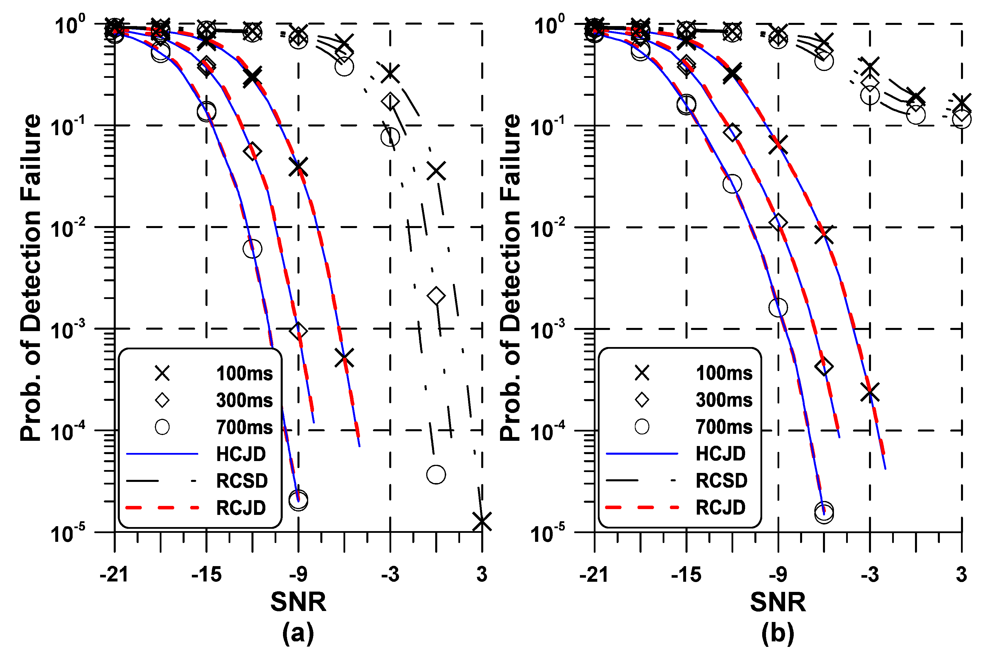
5. Simulation Results

LTE-MTC devices can be implemented to have only one receive antenna and a limited BW of 1.4 MHz. Therefore, the assignment of resources for LTE-MTC devices is based upon non-overlapping narrowbands consisting of 6 RBs. In our simulation, consider a 1.4 MHz LTE-MTC system with extended CP. More specifically, the carrier frequency is set to f c = 2 GHz, the DFT size to N = 128 , and subcarrier spacing to Δ f = 15 kHz. Therefore, the baseband signal is sampled with frequency 1 / T s = 1.92 MHz. The propagation scenarios are compliant with the Pedestrian A and Vehicular A channel models, which are represented by a maximum delay spread of 0.41 μ s and 2.15 μ s, respectively [23]. For initial synchronization, it is assumed that the MTC UE may have reference clock uncertainty of ± 20 ppm, which corresponds to M = 3 [16,17]. If not otherwise noted, we set M = 3 .
Figure 3 shows P f of existing and proposed detectors in the AWGN channel. To verify the accuracy the analysis presented in the previous section, the theoretical result is compared with the simulated result. From Figure 3a, it is shown that analytical results using numerical integral completely match simulated curves for both HCJD and RCJD methods when M = 1 , which validates the accuracy of performance analysis. In Figure 3b, the presence of the IFO degrades the performance of all detectors, which is more prominent in the case of the RCSD scheme. Not surprisingly, the performance of the detection methods is deteriorated as the local oscillator’s stability is getting worse, i.e., M increases.
Figure 4 presents the probabilities Prob { υ ^ υ } and Prob { n ^ i } , respectively, where the Pedestrian A channel is adopted with the MTC UE speed of 3 km/h. To meet the operating requirement at the coverage enhancement SNR of 14.2 dB [4], the decision statistic of the metrics of conventional and proposed schemes is averaged every 5 ms because PSS is transmitted twice every 10 ms radio frame. As a performance indicator, the number of PSS repetitions required to meet a target error probability of 10% at 14.2 dB SNR is defined as N r . It is evident that the performance of the HCJD scheme is almost the same as that of the RCJD scheme in detecting the IFO and SID, respectively. For both HCJD and RCJD schemes, it can be seen that the IFO detector requires N r = 140 to get an error probability of 10%, while N r = 60 is needed to detect the SID. It is worth pointing out that the adoption of the proposed scheme is more beneficial in estimating the SID than the IFO.
For the derivation of existing and proposed detectors, it has been assumed that the STO is completely removed. In practice, the existence of multipath channel may substantially affect the performance of the STO estimation scheme and small STO still remains uncompensated. The effect of residual STO on the probability of detection failure P f = Prob { ( υ ^ , n ^ ) ( υ , i ) } is shown in Figure 5, Assume that residual STO is uniformly generated from [ 0 , τ m a x ] with τ m a x being the maximum value of residual STO. When compared to the result in Figure 4, it is observed that the overall performance of the joint detection scheme is primarily dependent on the performance of the IFO detection scheme. Thus, to obtain the target rate at the required SNR in both HCJD and RCJD methods, N r = 140 PSS repetition is required. Although not shown in this figure, it follows that the RCSD method requires N r = 15,000 in the case of τ m a x = 0 . This observation indicates that MTC UE have to store 70 radio frames for successful synchronization in both HCJD and RCJD methods, which is equivalent to about 1/100 of the frame number needed for the RCSD method. As expected, the detection performance is influenced by the presence of the STO, especially in the case of the RCSD method. More importantly, it is shown that the performance degradation of the proposed RCJD scheme is negligible compared to the HCJD method, regardless of the SNR and SFO valUE.
Figure 6 depicts P f of existing and proposed detectors in the Vehicular A channel with mobile speed of 60 km/h. The simulation condition is identical to that in Figure 5. It is immediately seen that the trend of the probability curves is basically identical to that in Figure 5. Apparently, the increased frequency selectivity of the channel is harmful to the performance of existing and proposed estimation methods, which is because both methods are based on the differential correlation from adjacent PSS subcarriers. When compared to the observations in the Pedestrian A channel, the HCJD and RCJD methods still require at least N r = 140 PSS repetition for 90% probability of successful joint detection. Due to its high sensitivity to STO and fading impairments, the RCSD scheme does not work properly in dispersive channel environment. Regarding the number of flops, the RCJD scheme reduces the complexity by 31.8 % and 38.4 % over the HCJD and RCSD methods, respectively. It is summarized that the proposed RCJD method provides almost the same detection capability to the HCJD scheme in addition to having lower complexity. Since the proposed scheme is based on the PSS with a fixed length of N p = 62 subcarriers regardless of the system bandwidth, so it can be straightforwardly extended to the ordinary LTE device with larger system bandwidth.

6. Conclusions

In this paper, a complexity-effective joint cell and frequency synchronization algorithm is presented for the LTE-MTC system, and it exploits complex conjugate relation between two PSS signals. With this conjugate property, the IFO is detected with reduced search space, which facilitates low-complexity joint detection. The design of reduced search space structure contributes about 1/3 complexity saving. To meet the operating requirement of enhanced coverage MTC UE, its average estimate over multiple subframes is employed, obtaining the effect of time diversity. It has been verified from numerical results that the proposed joint detection method has approximately the same performance as the existing estimation scheme with substantial complexity reduction.

Author Contributions

Y.-A.J. implemented the initial synchronization method and performed computer simulations. D.S. complemented the problems of the proposed scheme and suggested solutions. Y.-H.Y. analyzed the detection accuracy of the proposed synchronization method and verified numerical analysis.

Funding

This research was supported by the Basic Science Research Program through the National Research Foundation of Korea (NRF) funded by the Ministry of Education (NRF-2018R1D1A1B07048819), and this research was supported by the Unmanned Vehicles Advanced Core Technology Research and Development Program through the National Research Foundation of Korea (NRF), Unmanned Vehicle Advanced Research Center (UVARC) funded by the Ministry of Science and ICT, the Republic of Korea (NRF-2017M1B3A2A01049997).

Conflicts of Interest

The authors declare no conflict of interest.

References

  1. 3GPP TS 136.300. Evolved Univsal Terrestrial Radio Access (EUTRA) and Evolved Universal Terrestrial Radio Access Network (E-UTRAN); Overall Description; Release 13; 3GPP: Sophia Antipolis, France, 2016. [Google Scholar]
  2. Akpakwu, G.A.; Silva, B.J.; Hancke, G.P.; Abu-Mahfouz, A.M. A survey on 5G networks for the Internet of Things: Communication tchnologies and challenges. IEEE Access 2018, 6, 3619–3647. [Google Scholar] [CrossRef]
  3. Chen, M.; Miao, Y.; Hao, Y.; Hwang, K. Narrow band Internet of Things. IEEE Access 2017, 5, 20557–20577. [Google Scholar] [CrossRef]
  4. 3GPP TR 36.888. Technical Specification Group Radio Access Network; Study on Provision of Low-Cost Machine-Type Communications (MTC) User equipment (UE) Based on LTE; Release 12; 3GPP: Sophia Antipolis Valbonne, France, 2013. [Google Scholar]
  5. Naddafzadeh-Shirazi, G.; Lampe, L.; Vos, G.; Bennett, S. Coverage enhancement techniqUE for machine-to-machine communications over LTE. IEEE Commun. Mag. 2015, 53, 192–200. [Google Scholar] [CrossRef]
  6. Lin, X.; Adhikary, A.; Eric Wang, Y.P. Random access preamble design and detection for 3GPP narrowband IoT systems. IEEE Wirel. Commun. Lett. 2016, 6, 640–643. [Google Scholar] [CrossRef]
  7. Elsaadany, M.; Ali, A.; Hamouda, W. Cellular LTE-A technologies for the future Internet-of-Things: Physical layer features and challenges. IEEE Commun. Surv. Tutor. 2017, 19, 2544–2572. [Google Scholar] [CrossRef]
  8. Chang, H.L.; Tsa, M.H. Optimistic DRX for machine-type communications in LTE-A network. IEEE Access 2018, 6, 9887–9897. [Google Scholar] [CrossRef]
  9. Balasubramanya, N.M.; Lampe, L.; Vos, G.; Bennett, S. On timing reacquisition and enhanced primary synchronization signal (ePSS) design for energy efficient 3GPP LTE MTC. IEEE Trans. Mob. Comput. 2017, 16, 2292–2305. [Google Scholar] [CrossRef]
  10. Golnari, A.; Shabany, M.; Nezamalhosseini, A.; Gulak, G. Design and implementation of time and frequency synchronization in LTE. IEEE Trans. Very Large Scale Int. Syst. 2015, 23, 2970–2982. [Google Scholar] [CrossRef]
  11. Sriharsha, M.R.; Dama, S.; Kuchi, K. A complete cell search and synchronization in LTE. EURASIP J. Wirel. Commun. Netw. 2017, 23, 1–14. [Google Scholar]
  12. Morelli, M.; Moretti, M. A maximum likelihood approach for SSS detection in LTE systems. IEEE Trans. Wirel. Commun. 2017, 16, 2423–2433. [Google Scholar] [CrossRef]
  13. Pec, R.; Choi, J.H.; Park, C.H.; Cho, Y.S. Synchronization method for long-term evolution-based machine-type communication in low-power cellular Internet of Things. Int. J. Distrib. Sens. Netw. 2016, 12, 1–14. [Google Scholar] [CrossRef]
  14. Nassralla, M.H.; Mansour, M.M.; Jalloul, L.M.A. A low-complexity detection algorithm for the primary synchronization signal in LTE. IEEE Trans. Veh. Technol. 2016, 65, 8751–8757. [Google Scholar] [CrossRef]
  15. Su, S.; Lin, Y.; Fan, Y. Joint sector identity and integer part of carrier frequency offset detection by phase-difference in long-term evolution cell search process. IET Commun. 2013, 7, 950–959. [Google Scholar] [CrossRef]
  16. Lin, J.C.; Sun, Y.-T.; Poor, H.V. Initial synchronization exploiting inherent diversity for the LTE sector search process. IEEE Trans. Wirel. Commun. 2016, 15, 1114–1128. [Google Scholar] [CrossRef]
  17. Morelli, M.; Moretti, M. A robust maximum likelihood scheme for PSS detection and integer frequency offset recovery in LTE systems. IEEE Trans. Wirel. Commun. 2016, 15, 1353–1363. [Google Scholar] [CrossRef]
  18. Chu, C.Y.; Lai, I.W.; Lan, Y.Y.; Chiueh, T.D. Efficient sequential integer CFO and sector identity detection for LTE cell search. IEEE Wirel. Commun. Lett. 2014, 3, 389–392. [Google Scholar] [CrossRef]
  19. Berggren, F.; Popovic, B.M. Primary synchronization signal for D2D communications in LTE-Advanced. IEEE Commun. Lett. 2015, 19, 1241–1244. [Google Scholar] [CrossRef]
  20. Popovic, B.M. Generalized chirp-like polyphase sequences with optimum correlation properties. IEEE Trans. Inf. Theory 1992, 30, 769–777. [Google Scholar] [CrossRef]
  21. Arellano-Vallea, R.B.; Genton, M.G. On fundamental skew distributions. J. Multivar. Anal. 2005, 96, 93–116. [Google Scholar] [CrossRef] [Green Version]
  22. Elshokry, A.M. Complexity and Performance Evaluation of Detection Schemes for Spatial Multiplexing MIMO Systems; Islamic University: Islamabad, Pakistan, 2010. [Google Scholar]
  23. 3GPP TS 136.101. LTE; Evolved Universal Terrestrial Radio Access (E-UTRA); User Equipment (UE) Radio Transmission and Reception; Release 14; 3GPP: Sophia Antipolis, France, 2017. [Google Scholar]
Figure 1. Long term evolution frequency division duplex downlink frame structure.
Symmetry 11 01394 g001
Figure 2. Initial cell search procedure in an long term evolution downlink.
Symmetry 11 01394 g002
Figure 3. Performance of the joint detection methods versus signal-to-noise ratio in the additive white Gaussian noise channel: (a) M = 1 ; (b) M = 2 ; and M = 3 .
Symmetry 11 01394 g003
Figure 4. Performance of integer carrier frequency offset and sector identity detectors in the Pedestrian A channel when τ m a x = 0 : (a) integer carrier frequency offset detector (b) sector identity detector.
Symmetry 11 01394 g004
Figure 5. Performance of the joint detection methods in the Pedestrian A channel: (a) τ m a x = 0 ; (b) τ m a x = 5 .
Symmetry 11 01394 g005
Figure 6. Performance of the joint detection methods in the Vehicular A channel: (a) τ m a x = 0 ; (b) τ m a x = 5 .
Symmetry 11 01394 g006

