Secure Beamforming in 5G-Based Cognitive Radio Network

Abstract
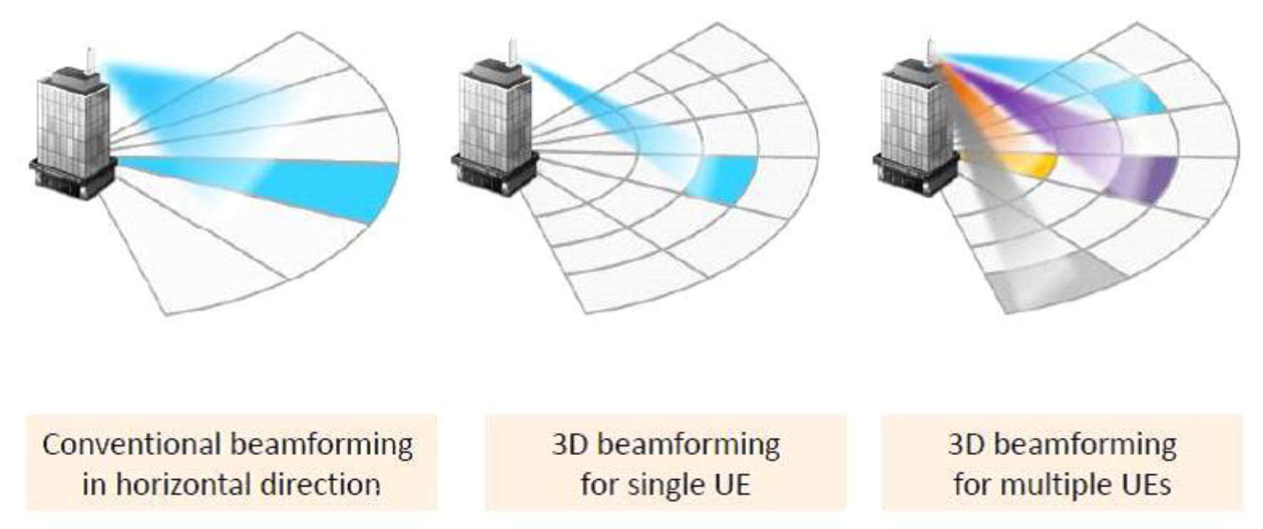
1. Introduction
2. Related Work and Contributions
2.1. Zero-Forcing Beamforming (ZFBF) Related Works
2.2. Mimimum Mean Squared Error (MMSE) Related Works
3. System Model
3.1. Secure Beamforming in 5G-Based CRN
3.2. Proposed Beamformer
3.3. Proposed Technique in Cascaded Transmission of MIMO-NOMA Network
3.4. Secrecy Outage Probability
4. Numerical Evaluation
5. Motivation and Contribution of the Article
6. Discussion
7. Conclusions
Author Contributions
Funding
Conflicts of Interest
Abbreviations
| CRN | cognitive radio network |
| NOMA | non-orthogonal multiple access |
| MIMO | multiple-input-multiple-output |
| 5G | fifth generation |
| SUs | secondary users |
| PUs | primary users |
| SC | subcarrier |
| CJ | cooperative jamming |
| SSPA | smart sensor protocol algorithm |
| PLS | physical layer security |
| ZFBF | zero forcing beamforming |
| BF | beamforming |
| CSTN | cognitive satellite terrestrial network |
| SDA | software defined architecture |
| MISOME-SWIPT | multiple input, single output multiple-eavesdropper simultaneous wireless information and power transferring |
| SEE | secrecy energy efficiency |
| CSI | channel state information |
| UPA | uniform planar array |
| BS | base station |
| AoA | angle of arrival |
| Eves | eavesdropper |
| SR | secrecy rate |
| IPF | iterative penalty function |
| MISO | multi-input single-output |
| ST | secondary transmitter |
| SR | secondary receiver |
| PS | power splitting |
| SDR | software defined radio |
| PSO | particle swarm optimization |
| EPS | equal power splitting |
| MMSE | minimum mean square error |
| NMSE | normalized mean square error |
| ML | maximum likelihood |
| SIC | successive interference cancellation |
| OTP | opportunistic transmission protocol |
| MUD | multiuser detection |
| MC DS-CDMA | multicarrier direct-sequence code-division multiple access |
| IC | interference cancellation |
| UE | user equipment |
| AWGN | additive white Gaussian noise |
| CoBF | coordinated beamforming |
| SNR | signal to noise ratio |
| RF | radio frequency |
| IoT | Internet of Things |
| SOP | secrecy outage probability |
References
- Zeng, M.; Yadav, A.; Dobre, O.A.; Tsiropoulos, G.I.; Poor, H.V. Capacity comparison between MIMO-NOMA and MIMO-OMA with multiple users in a cluster. IEEE J. Sel. Areas Commun. 2017, 35, 2413–2424. [Google Scholar] [CrossRef]
- Islam, S.M.R.; Zeng, M.; Dobre, O.A.; Kwak, K.S. Resource allocation for downlink NOMA systems: Key techniques and open issues. IEEE Wirel. Commun. 2018, 25, 40–47. [Google Scholar] [CrossRef]
- Shin, W.; Vaezi, M.; Lee, B.; Love, D.J.; Lee, J.; Poor, H.V. Coordinated beamforming for multi-cell MIMO-NOMA. IEEE Commun. Lett. 2017, 21, 84–87. [Google Scholar] [CrossRef]
- Ding, Z.; Adachi, F.; Poor, H.V. The application of MIMO to nonorthogonal multiple access. IEEE Trans. Wirel. Commun. 2016, 15, 537–552. [Google Scholar] [CrossRef]
- Ding, Z.; Schober, R.; Poor, H.V. A general MIMO framework for NOMA downlink and uplink transmission based on signal alignment. IEEE Trans. Wirel. Commun. 2016, 15, 4438–4454. [Google Scholar] [CrossRef]
- Xu, L.; Nallanathan, A.; Pan, X.; Yang, J.; Liao, W. Security-Aware Resource Allocation with Delay Constraint for NOMA-Based Cognitive Radio Network. IEEE Trans. Inf. Forensics Secur. 2018, 13, 366–376. [Google Scholar] [CrossRef]
- Duan, W.; Jiang, X.Q.; Wen, M.; Wang, J.; Zhang, G. Two-Stage Superposed Transmission for Cooperative Noma Systems. IEEE Access 2018, 6, 3920–3931. [Google Scholar] [CrossRef]
- Liu, Y.; Qin, Z.; Elkashlan, M.; Gao, Y.; Hanzo, L. Enhancing the physical layer security of non-orthogonal multiple access in large-scale networks. IEEE Trans. Wirel. Commun. 2017, 16, 1656–1672. [Google Scholar] [CrossRef]
- Jiang, M.; Li, Y.; Zhang, Q.; Li, Q.; Qin, J. Secure beamforming in downlink MIMO nonorthogonal multiple access networks. IEEE Signal Process. Lett. 2017, 24, 1852–1856. [Google Scholar] [CrossRef]
- Zhang, H.; Yang, N.; Long, K.; Pan, M.; Karagiannidis, G.K.; Leung, V.C. Secure Communications in NOMA System: Subcarrier Assignment and Power Allocation. IEEE J. Sel. Areas Commun. 2018, 36, 1441–1452. [Google Scholar] [CrossRef]
- Chen, J.; Yang, L.; Alouini, M.S. Physical layer security for cooperative NOMA systems. IEEE Trans. Veh. Technol. 2018, 67, 4645–4649. [Google Scholar] [CrossRef]
- Nibedita, N.; Sudhan, M.; Hsiao-Chun, W. Secure Beamforming for MIMO-NOMA Based Cognitive Radio Network. IEEE Commun. Lett. 2018, 22, 1708–1711. [Google Scholar]
- Lin, M.; Lin, Z.; Zhu, W.P.; Wang, J.B. Joint Beamforming for Secure Communication in Cognitive Satellite Terrestrial Networks. IEEE J. Sel. Areas Commun. 2018, 36, 1017–1029. [Google Scholar] [CrossRef]
- Dong, Y.; Hossaini, M.J.; Cheng, J.; Leung, V.C. Robust Energy Efficient Beamforming in MISOME-SWIPT Systems with Proportional Secrecy Rate. IEEE J. Sel. Areas Commun. 2018, 37, 202–215. [Google Scholar] [CrossRef]
- Lin, Z.; Lin, M.; Wang, J.B.; Huang, Y.; Zhu, W.P. Robust Secure Beamforming for 5G Cellular Networks Coexisting with Satellite Networks. IEEE J. Sel. Areas Commun. 2018, 36, 932–945. [Google Scholar] [CrossRef]
- Pham, V.T.; Koo, I. Optimal Multiuser MISO Beamforming for Power-Splitting SWIPT Cognitive Radio Networks. IEEE Access 2017, 5, 14141–14153. [Google Scholar]
- Irfan, A.; Hedi, K.; Adnan, S.; Ahmed, M.; Kwang, S.K.; Eli De, P.; Ingrid, M. A Survey on Hybrid Beamforming Techniques in 5G: Architecture and System Model Perspectives. IEEE Commun. Surv. Tutor. 2018, 20, 3060–3097. [Google Scholar]
- Deepanramkumar, P.; Karuppiah, M.; Hafizul, I.S.K.; Mohammad, S.O. Secure cognitive radio-based synchronized transmission of 5G signals using massive MIMO-OFDM-ES. Int. J. Commun. Syst. 2018, 31, e3805. [Google Scholar]
- Ehab, A.; Mahamod, I.; Rosdiadee, N.; Nor, F.A. Beamforming techniques for massive MIMO systems in 5G: Overview, classification, and trends for future research. Front. Inf. Technol. Electron. Eng. 2017, 18, 753–772. [Google Scholar]
- Ju, M.; Qian, J.; Li, Y.; Tan, G.; Li, X. Comparison of multiuser MIMO systems with MF, ZF and MMSE receivers. In Proceedings of the IEEE Third International Conference on Information Science and Technology (ICIST), Yangzhou, China, 23–25 March 2013. [Google Scholar]
- Lin, H.; Shin, W.Y. Non-Orthogonal Random Access in MIMO Cognitive Radio Networks: Beamforming, Power Allocation, and Opportunistic Transmission. PLoS ONE 2017, 12, e0169902. [Google Scholar] [CrossRef]
- Sun, F.; de Elisabeth, C. Leakage-Based MMSE Beamforming Design for a MIMO Interference Channel. IEEE Signal Process. Lett. 2012, 19, 368–371. [Google Scholar] [CrossRef]
- Yang, L.L.; Wang, L.C. Zero-Forcing and Minimum Mean-Square Error Multiuser Detection in Generalized Multicarrier DS-CDMA Systems for Cognitive Radio. EURASIP J. Wirel. Commun. Netw. 2008, 2008, 541410. [Google Scholar] [CrossRef]
- Masterson, C. Massive MIMO and Beamforming: The Signal Processing Behind the 5G Buzzwords. Analog Dialogue 2017, 51, 10. [Google Scholar]
- Yang, Z.; Ding, Z.; Fan, P.; Al-Dhahir, N. A general power allocation scheme to guarantee quality of service in downlink and uplink NOMA systems. IEEE Trans. Wirel. Commun. 2016, 15, 7244–7257. [Google Scholar] [CrossRef]
- Eiichi, Y.; Tomoo, U.; Zen, K.; Satoru, Y.; Takeshi, M.; Fumihiko, M.; Masakazu, W. MMSE Beam Forming on Fast-Scanning Phased Array Weather Radar. IEEE Trans. Geosci. Remote Sens. 2013, 51, 3077–3088. [Google Scholar]


| Parameter | Value |
|---|---|
| Network Size | 200 × 200 m2 |
| Channel Bandwidth | 1 MHz |
| Rayleigh fading channel, | 0.8 |
| Path-loss exponent, | 3 |
| Radius of inner disc, ri | 10 |
| Radius of outer disc, ro | 20 |
| Data rate for PU, | 0.25, 1 |
| Data rate for SU, | 1, 4 |
| Number of antennas for BS, M | 2 |
| Number of antennas for user, N | 2 |
| Number of clusters of each cell, L | 4 |
| Number of cells, C | 2 |
| Number of bits/symbols, Bi | 106 bits |
© 2019 by the authors. Licensee MDPI, Basel, Switzerland. This article is an open access article distributed under the terms and conditions of the Creative Commons Attribution (CC BY) license (http://creativecommons.org/licenses/by/4.0/).
Share and Cite
Antony, H.S.M.; Lakshmanan, T. Secure Beamforming in 5G-Based Cognitive Radio Network. Symmetry 2019, 11, 1260. https://doi.org/10.3390/sym11101260
Antony HSM, Lakshmanan T. Secure Beamforming in 5G-Based Cognitive Radio Network. Symmetry. 2019; 11(10):1260. https://doi.org/10.3390/sym11101260
Chicago/Turabian StyleAntony, Hyils Sharon Magdalene, and Thulasimani Lakshmanan. 2019. "Secure Beamforming in 5G-Based Cognitive Radio Network" Symmetry 11, no. 10: 1260. https://doi.org/10.3390/sym11101260
APA StyleAntony, H. S. M., & Lakshmanan, T. (2019). Secure Beamforming in 5G-Based Cognitive Radio Network. Symmetry, 11(10), 1260. https://doi.org/10.3390/sym11101260