Frequency-Octupling Millimeter-Wave Optical Vector Signal Generation via an I/Q Modulator-Based Sagnac Loop


Abstract
1. Introduction
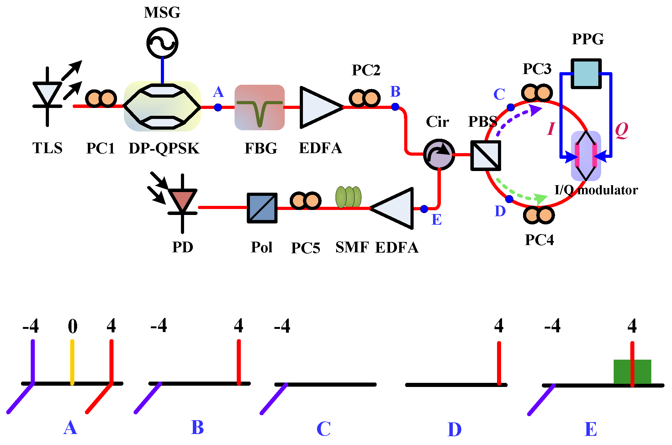
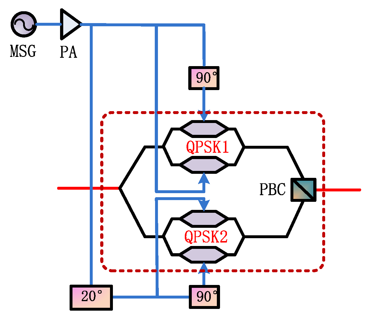
2. Principle
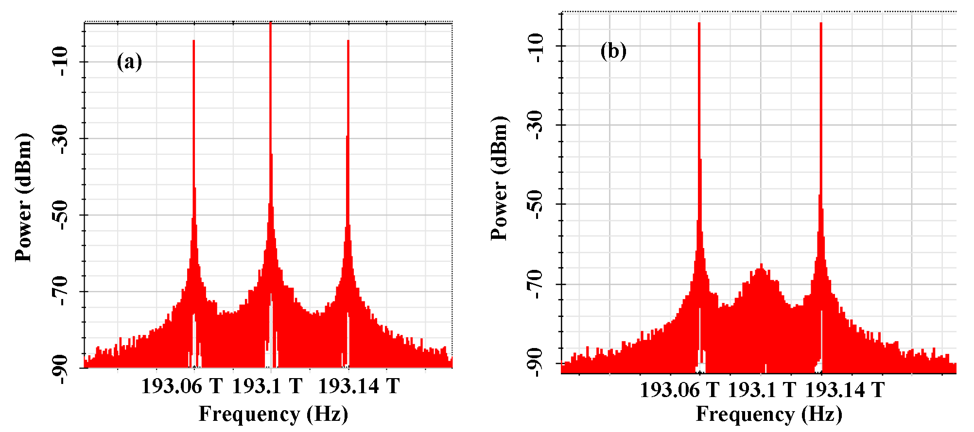
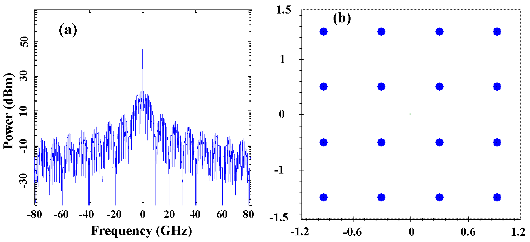
3. Simulation Results
4. Conclusions
Author Contributions
Funding
Acknowledgments
Conflicts of Interest
References
- Kitayama, K.; Maruta, A.; Yoshida, Y. Digital coherent technology for optical fiber and radio-over-fiber transmission systems. J. Lightw. Technol. 2014, 32, 3411–3420. [Google Scholar] [CrossRef]
- Huang, H.T.; Liang, W.L.; Lin, C.T.; Wei, C.C.; Chi, S. 100-GHz DD-OFDM-RoF system over 150-km fiber transmission employing pilot-aided phase noise suppression and bit-loading algorithm. Opt. Exp. 2014, 22, 3938–3943. [Google Scholar] [CrossRef] [PubMed]
- Li, X.; Dong, Z.; Yu, J.; Chi, N.; Shao, Y.; Chang, G.K. Fiber-wireless transmission system of 108 Gb/s data over 80 km fiber and 2 × 2 multiple-input multiple-output wireless links at 100 GHz W-bandfrequency. Opt. Lett. 2012, 37, 5106–5108. [Google Scholar] [CrossRef] [PubMed]
- Wells, J. Faster than fiber: The future of multi-Gb/s wireless. IEEE Microw. Mag. 2009, 10, 104–112. [Google Scholar] [CrossRef]
- Yu, J.; Jia, Z.; Yi, L.; Su, Y.; Chang, G.-K.; Wang, T. Optical millimeter-wave generation or up-conversion using external modulators. IEEE Photon. Technol. Lett. 2006, 18, 265–267. [Google Scholar]
- Lin, C.-T.; Shih, P.-T.; Jiang, W.-J.; Wong, E.-Z.; Chen, J.J.; Chi, S. Photonic vector signal generation at microwave/millimeter-wave bands employing an optical frequency quadrupling scheme. Opt. Lett. 2010, 34, 2171–2173. [Google Scholar] [CrossRef] [PubMed]
- Li, W.; Yao, J. Microwave generation based on optical domain microwave frequency octupling. IEEE Photon. Technol. Lett. 2010, 22, 24–26. [Google Scholar] [CrossRef]
- Zhang, J.; Chen, H.; Chen, M.; Wang, T.; Xie, S. A photonic microwave frequency quadrupler using two cascaded intensity modulators with repetitious optical carrier suppression. IEEE Photon. Technol. Lett. 2007, 19, 1057–1059. [Google Scholar] [CrossRef]
- Yu, J.; Jia, Z.; Wang, T.; Chang, G.K. Centralized lightwave radio-over-fiber system with photonic frequency quadrupling for high-frequency millimeter-wave generation. IEEE Photon. Technol. Lett. 2007, 19, 1499–1501. [Google Scholar] [CrossRef]
- Li, X.; Yu, J.; Xiao, J.; Chi, N.; Xu, Y. W-band PDM-QPSK vector signal generation by MZM-based photonic frequency octupling and precoding. IEEE Photon. J. 2015, 7, 7101906. [Google Scholar] [CrossRef]
- Li, X.; Zhang, J.; Xiao, J.; Zhang, Z.; Xu, Y.; Yu, J. W-band 8QAM vector signal generation by MZM-based photonic frequency octupling. IEEE Photon. Technol. Lett. 2015, 27, 1257–1260. [Google Scholar] [CrossRef]
- Zhao, L.; Yu, J.; Chen, L.; Min, P.; Li, J.; Wang, R. 16QAM vector millimeter-wave signal generation based on phase modulator with photonic frequency doubling and precoding. IEEE Photon. J. 2016, 8, 5500708. [Google Scholar] [CrossRef]
- Li, X.; Yu, J.; Chang, G. Frequency-quadrupling vector mm-wave signal generation by only one single-drive MZM. IEEE Photon. Technol. Lett. 2016, 28, 1302–1305. [Google Scholar] [CrossRef]
- Dong, Z. 64QAM vector radio-frequency signal generation based on phase precoding and optical carrier suppression modulation. IEEE Photon. J. 2016, 8, 2630306. [Google Scholar] [CrossRef]
- Wang, Y.; Yu, J.; Li, X.; Xu, Y.; Chi, N.; Chang, G.K. Photonic vector signal generation employing a single-drive MZM-based optical carrier suppression without precoding. J. Lightw. Technol. 2015, 33, 5235–5241. [Google Scholar] [CrossRef]
- Ma, J. Dual-tone QPSK optical millimeter-wave signal generation by frequency nonupling the RF signal without phase precoding. IEEE Photon. J. 2016, 8, 2630306. [Google Scholar] [CrossRef]
- Li, X.; Zhao, S.; Zhang, Y.; Zhu, Z.; Pan, S. Generation of a frequency-quadrupled phase-coded signal with large tunability. IEEE Photon. Technol. Lett. 2016, 28, 1980–1983. [Google Scholar] [CrossRef]
- Gao, Y.; Wen, A. Analog Photonic Link with Tunable Optical Carrier to Sideband Ratio and Balanced Detection. IEEE Photon. J. 2017, 9, 7200510. [Google Scholar] [CrossRef]
- Zhang, Y.; Zhang, F.; Pan, S. Generation of Frequency-Multiplied and Phase-Coded Signal Using an Optical Polarization Division Multiplexing Modulator. IEEE Trans. Microw. Theory Technol. 2017, 65, 651–660. [Google Scholar] [CrossRef]
- Li, W.; Yao, J. Dynamic range improvement of a microwave Photonic link based on bi-directional use of a polarization modulator in a Sagnac loop. Opt. Exp. 2013, 21, 15692–15697. [Google Scholar] [CrossRef] [PubMed]


© 2019 by the authors. Licensee MDPI, Basel, Switzerland. This article is an open access article distributed under the terms and conditions of the Creative Commons Attribution (CC BY) license (http://creativecommons.org/licenses/by/4.0/).
Share and Cite
Yang, Z.; Qu, K.; Liu, X. Frequency-Octupling Millimeter-Wave Optical Vector Signal Generation via an I/Q Modulator-Based Sagnac Loop. Symmetry 2019, 11, 84. https://doi.org/10.3390/sym11010084
Yang Z, Qu K, Liu X. Frequency-Octupling Millimeter-Wave Optical Vector Signal Generation via an I/Q Modulator-Based Sagnac Loop. Symmetry. 2019; 11(1):84. https://doi.org/10.3390/sym11010084
Chicago/Turabian StyleYang, Zhixian, Kun Qu, and Xiang Liu. 2019. "Frequency-Octupling Millimeter-Wave Optical Vector Signal Generation via an I/Q Modulator-Based Sagnac Loop" Symmetry 11, no. 1: 84. https://doi.org/10.3390/sym11010084
APA StyleYang, Z., Qu, K., & Liu, X. (2019). Frequency-Octupling Millimeter-Wave Optical Vector Signal Generation via an I/Q Modulator-Based Sagnac Loop. Symmetry, 11(1), 84. https://doi.org/10.3390/sym11010084