Abstract
Multiple-input multiple-output orthogonal frequency division multiplexing (MIMO-OFDM) is appealing for the provision of high spectral efficiency in digital terrestrial broadcast systems. To fully obtain its advantageous features, it is very important to remove the frequency mismatch between the transmitter and the receiver. In this paper, we present the performance analysis of joint estimation of carrier and sampling frequency offsets in the MIMO-OFDM-based advanced television systems committee (ATSC) 3.0 system. In the MIMO-OFDM ATSC system, the continual pilot (CP) is primarily utilized to perform frequency synchronization. To efficiently suppress an unwanted bias introduced by the presence of random-likely located CPs, an optimal pilot subset is selected to form the basis of least squares frequency-offset estimation. A closed-form mean squared error is derived in the context of MIMO-OFDM, considering the multipath fading channel. We show via computer simulations and numerical analysis that the proposed estimation method achieves higher estimation accuracy than the existing estimation method.
1. Introduction
Orthogonal frequency division multiplexing (OFDM) has been successfully applied in many high data rate communication systems because of its attractive spectrum usage efficiency. Due to its benefits of wide available bandwidth, OFDM has been considered for optical communication systems. Optical OFDM can be used for short and long distance applications such as optical access networks, multimode fiber transmissions, free space optical systems, and indoor visible light communications [1,2,3,4,5]. In the broadcasting domain, the use of OFDM modulation facilitates the deployment of single frequency networks (SFN) in numerous broadcast systems such as digital radio mondiale (DRM), digital video broadcasting-terrestrial-second generation (DVB-T2), DVB next-generation handheld (DVB-NGH) systems, integrated services digital broadcasting-terrestrial (ISDB-T) systems, and the advanced television systems committee (ATSC) 3.0 [6,7,8,9,10]. DVB-T2 was designed primarily to provide interactive content that requires high bandwidth, such as HDTV and 3D TV [11]. To support these requirements, the DVB-T2 standard has incorporated a widely used multiple-input single-output (MISO) antenna scheme [7]. The DVB-NGH system is the first broadcast standard to integrate a multiple-input multiple-output (MIMO) scheme in order to increase bandwidth efficiency without any need for extra wireless bandwidth [12]. Recently, ATSC 3.0 and ISDB-T have adopted MIMO to achieve higher throughput and increase coverage [13,14]. Many studies have been carried out to improve MIMO configurations and transceivers in digital terrestrial broadcast systems [14,15,16].
Despite many advantageous features, the OFDM-based ATSC 3.0 system has a few key issues that have to be addressed. One of the biggest weaknesses of OFDM is its vulnerability to synchronization mismatches, including symbol timing offset (STO), carrier frequency offset (CFO), and sampling frequency offset (SFO) in a frequency-selective fading environment [17]. If these effects are not properly compensated, OFDM systems can suffer from severe inter-symbol interference (ISI) or inter-channel interference (ICI), which downgrades the performance of OFDM and MIMO-OFDM systems. To eliminate ICI and ISI effects, the receiver must first estimate the correct STO [18,19]. Second, it is essential that the frequency offset on the OFDM block is estimated and corrected to remove ICI. In particular, the performance of OFDM receivers is greatly affected by SFO as the fast Fourier transform (FFT) size becomes larger [20], which usually occurs in a typical broadcast system. Therefore, the challenges in the MIMO-OFDM-based ATSC 3.0 system are its susceptibility to the frequency synchronization between the transmitter and the receiver. In order to help acquire synchronization, the ATSC 3.0 system provides several types of pilot symbols such as scattered pilots (SPs), edge pilots (EPs), continual pilots (CPs), and subframe boundary pilots (SBPs) [10]. The SPs, EPs, and SBPs are mainly dedicated to estimate the channel, whereas CPs are present to assist time and frequency estimation [21]. To maximize the advantages of MIMO-OFDM, it is therefore of crucial importance to accurately estimate the CFO and SFO [22,23]. In the literature, a number of pilot-assisted approaches, from maximum likelihood estimation (MLE) to linear least-squares estimation (LSE) strategies [22,23,24,25,26,27,28,29,30,31,32,33,34,35], have been presented to obtain accurate CFO and SFO estimates. The MLE is well known to be capable of achieving high accuracy in joint estimation of CFO and SFO, but its high complexity limits its practical use [22,23,24,25]. To solve the complexity issue, a considerable amount of research has been devoted to the low complexity variants of joint MLE [26,27,28,29,30,31,32,33,34,35]. In [26,27,28,29,30,31,32], the ad-hoc-based CFO and SFO estimation strategy was developed calculating the phase difference from two consecutive pilot symbols with symmetric and uniform distribution across DC. In [33,34,35], a decoupled estimation of CFO and SFO was proposed, which is still computation-intensive for real-time processing. Hence, more efficient frequency estimation and its complete performance analysis in a multipath fading channel is a key challenge in realizing high-performance MIMO-OFDM receivers.
In this paper, the performance analysis of joint CFO and SFO estimator for the MIMO-OFDM ATSC broadcast system is presented in a the multipath fading channel. The CPs are used for the purpose of synchronization, and an optimal CP subset is searched to form the basis of robust estimation. The choice of the optimal pilot subset plays an important role on removing a bias produced by using random-likely distributed CPs. To assess the usefulness of the proposed LSE method, the mean squared error (MSE) is theoretically derived for the MIMO-OFDM ATSC system in a frequency-selective fading channel. It is demonstrated from numerical analysis that the joint estimation scheme using optimal pilot subset offers a robust estimation performance with a low computational burden, in comparison to the existing method.
This paper is structured as follows. Section 2 describes the signal model in the MIMO-OFDM ATSC system. In Section 3, the existing LSE method is applied to the MIMO-OFDM ATSC system. In Section 4, an improved LSE method is presented and the MSE performance is numerically analyzed in the MIMO-OFDM ATSC system. The simulation results and discussions showing the advantages of the proposed LSE method are presented in Section 5. Section 6 concludes this paper.
The notations used in this paper are listed as follows. , , , and denote the operations taking the absolute value, complex conjugation, expectation, and real part of enclosed quantity, respectively. ∠ and ⊗ indicate the radian angle and convolution operators. The imaginary unit is .
2. System Description
Consider a MIMO-OFDM system having non-zero subcarriers, receive antennas, and transmit antennas. The frequency-domain signal is transformed by N-point inverse FFT (IFFT) to generate the time-domain signal and a guard interval (GI) with samples is appended to the front of the OFDM symbol to combat ISI. The n-th sample transmitted from transmit antenna m during the l-th period can then be written by
where is a complex signal from transmit antenna m at subcarrier k with symbol energy and the normalization factor is used to keep the transmission power constant. As a consequence, one OFDM symbol of effective duration is generated, where T is the sampling time and . In the frequency domain, subcarriers are zero-padded. The continuous-time baseband signal transmitted at antenna m is expressed as
where is the GI duration and is the shaping pulse given as
Figure 1 depicts the block diagram of the MIMO-OFDM receiver including the synchronization block. Since the frequency of the local oscillator is not exactly matched to the received carrier frequency , the time-domain signal in receiver antenna r can be given by
where means the CFO in Hz, is the channel impulse response (CIR) from transmit antenna m to receive antenna r, and is a zero-mean additive white Gaussian noise (AWGN) process at receive antenna r. In Equation (4), takes the form
where P is the number of multipaths, and and denote the attenuation and delay of the p-th multipath from transmit antenna m to receive antenna r, respectively. Since the multiple antennas are usually co-located, only one oscillator is referenced in either the transmit side or receiver side. Moreover, the differences in Doppler shift between all transmit–receive antenna pairs are small in typical broadcasting systems. With those implications in mind, we consider scenarios where all transmit–receive antenna couples experience a single common CFO and SFO as discussed in [36,37,38].
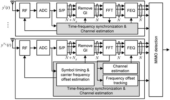
Figure 1.
System model of the multiple-input multiple-output orthogonal frequency division multiplexing-based advanced television systems committee (ATSC) receiver.
The received signal is sampled at time instants , which leads to a SFO . At the receiver, the sampled signal at time instants becomes [34]
where is the normalized CFO by the subcarrier spacing , and and are the samples of multiplicative channel and additive noise, respectively. As shown in Figure 1, the estimation of initial STO and CFO is performed during pre-FFT phase, which is usually based on the inherent redundant information in OFDM symbols. After FFT, residual CFO and SFO are estimated and tracked using either CP or SP. After the time and frequency synchronization process, the receiver performs channel estimation and MIMO detection in a sequential or iterative manner [39]. Since this paper focuses on the post-FFT synchronization processing, we consider the situation where coarse CFO estimation has been done before FFT is performed. In addition, we assume the perfect knowledge of the STO at the receiver. After discarding the GI and performing N-point FFT for the l-th OFDM symbol, the received OFDM signal in receiver antenna r at subcarrier k appears as
which is further derived as [33,34]
where , , is the equivalent channel transfer function (CTF) from transmit antenna m to receive antenna r with variance , is a zero-mean complex ICI with variance at receive antenna r, and is a zero-mean complex AWGN with variance at receive antenna r. For typical values of and , and [17]. Since the same common CPs are transmitted from the transmit antennas in the MIMO-OFDM ATSC system [10], an equivalent CTF at the receive antenna r can be treated as a sum of CTFs from transmit antennas
which is modeled as a complex zero-mean Gaussian process with variance .
3. The Conventional LSE Scheme
Since many pilot symbols are dedicated to the purpose of time and frequency synchronization in the ATSC 3.0 system, we focus on the pilot-based LSE scheme [28,29,30,31] as a reference to the proposed method. In this paper, we consider the common CPs as pilot symbols, which are continuously inserted at a fixed subcarrier position. The channel is assumed to remain stationary during two symbol periods so that . We omit the superscript m in assuming that the pilot symbols are the same among the transmit antennas. Based upon two consecutive CPs, the pilot-compensated signals in the MIMO configuration is represented by
where , is the set of pilot subcarrier indices, is the ICI component written as
and is the AWGN component written as
For notation simplicity, the argument of takes the form
where means an appropriate noise term after taking an argument. When the common CPs are entirely used for synchronization, the CFO and SFO are obtained by applying the LS regression to as
and
where denotes the set of positive CP subcarriers containing members, denotes the set of negative CP subcarriers containing members, stands for the total number of pilot subcarriers present in , , and . Note that the second term of the right-hand side (RHS) of Equations (14) and (15) is the intrinsic interference caused by AWGN and ICI, whereas the third term is the extra bias introduced by the existence of non-symmetrically located CPs. Among them, the interferences due to ICI and CPs do not vanish even as signal-to-noise ratio (SNR) grows.
Since CPs are randomly distributed in the ATSC 3.0 system, it is not guaranteed that . In such a case, an unwanted bias can be occurred by non-symmetrically distributed CPs, which leads to an irreducible MSE floor. To account for this issue, an effective LSE scheme is suggested based on a pilot subset selection in the following section.
4. The Proposed LSE Scheme
This section presents an effective joint CFO and SFO estimation scheme in the MIMO-OFDM ATSC system and its performance analysis is presented in the multipath fading channel. The improved CFO and SFO estimation scheme is achieved by properly choosing a pilot subset so that a bias incurred by using randomly distributed CPs can be eliminated.
4.1. Pilot Selection
Let and be the searched optimal subsets for positive and negative subcarrier frequencies around DC, respectively. The argument over the pilot-compensated signal is then decomposed as
with
where contains the elements, contains the elements, and is the number of CPs utilized in the proposed estimation scheme. Similarly, we have
where
In order to independently estimate the CFO and SFO using Equations (16) and (18), should be zero because of non-zero valued SFO and CFO in the third term of the RHS of Equations (16) and (18), respectively. In this paper, the goal of the pilot subset selection scheme is to make zero as well as maximize and at the same time. For this purpose, two subsets and are selected to meet the following criteria:
and
where returns the argument which makes the enclosed objective function zero, and stand for the possible combinatorial subset whose elements are and , respectively, and and are the sum of the number of combinations choosing g subcarriers from and subcarriers respectively given by
With the use of the searched subsets from Equations (20) and (22), the proposed LSE of CFO and SFO can be shown to be of the following forms:
and
which indicates that the MSE performance of the CFO estimation method is primarily enhanced in proportion to , whereas both the number and locations of CPs determine the performance of the SFO estimation method.
4.2. MSE Analysis
Next, the analytical expression for MSE of Equations (23) and (24) is obtained in the multipath fading channel. For notational convenience, we may rewrite Equation (10) as
where , , and . Since CPs are transmitted at a boosted power level of 8.52 dB, under high SNR condition, one safely assumes that
where and . Notice that and are statistically identical to and , respectively.
With the use of optimal subsets and , the estimation error for and is computed by
and
Recognizing that , we obtain the following expressions:
and
By placing the antennas sufficiently apart, the channel between all transmit–receive antenna couples is considered to be statistically independent. Referring from Equation (11), the variance of in Equation (29) can be readily shown to be
where the first expectation of the RHS is further derived into
Since in Equation (25) is non-centrally chi-square distributed having degrees of freedom, one obtains that for and
where is the exponential integral.
4.3. Computational Complexity
In this section, the complexity of the frequency-offset estimation schemes is discussed in terms of the number of arithmetic operations. The conventional scheme requires complex multiplications and complex additions to compute Equation (10). In Equations (14) and (15), real multiplications and real additions are needed for each couple . Since the proposed scheme uses only pilot symbols selected from full pilot symbols, the computational processing required in the proposed method can be identical to that used in the existing method, replacing with . Table 1 compares the computational complexity between the existing and proposed methods. One readily find that the computational burden of the proposed method is lower than that of the conventional method because .

Table 1.
Arithmetic operations of the frequency-offset estimation schemes.
5. Simulation Results and Discussions
The performance of the joint LSE schemes is assessed in the MIMO-OFDM ATSC system. The main system parameters of the ATSC 3.0 are summarized in Table 2. In this work, we have considered 8 k and 16 k modes. The signal bandwidth of 6 MHz and the sampling interval of are considered [10]. In the simulations, 6-path Hilly Terrain channel model whose maximum delay is is adopted [40], and the multipath channel is implemented according to Equation (5). In this channel model, the multipath intensity profile of the channel is characterized by two clusters, where each cluster is exponentially decreasing in delay. Table 3 summarizes the channel profile of 6-path Hilly Terrain channel model. To demonstrate the exactness of the MSE analysis, Doppler effects due to mobility are excluded in the adopted channel model. To find the optimal subset simultaneously meeting the constraint of Equations (20) and (22), we perform an exhaustive search over all combinations of possible subsets, and it is thereby obtained that for 8 k mode and for 16 k mode. In the sequel, the selected mode-specific values of are used for the proposed estimation scheme.
Table 2.
System parameters.
Table 3.
Channel profiles.
Figure 2 depicts a comparison between the numerical and simulated results of the frequency-offset estimation schemes when , ppm, and 8 k mode is used. The probability of Rayleigh distributed random variable larger than a minimum level is so that 99.9% level of Rayleigh fading is realized in the case of dB, which is used to obtain the MSE in the case of . One can find that there is an excellent match between the numerical results and those given by the simulation in the multipath fading channel except at low SNR values. It is evident that the use of optimal subsets makes the proposed LSE achieve a better performance over the conventional LSE. In the case of SFO, it is observed that the ICI becomes a dominant term in comparison with that of an unwanted bias from the use of CPs. Especially, the performance of the proposed scheme becomes slightly degraded due to the reduced number of pilot symbol when dB, whereas its performance is improved thanks to the optimal subset selection at 15 dB or higher, compared to that of the conventional scheme.
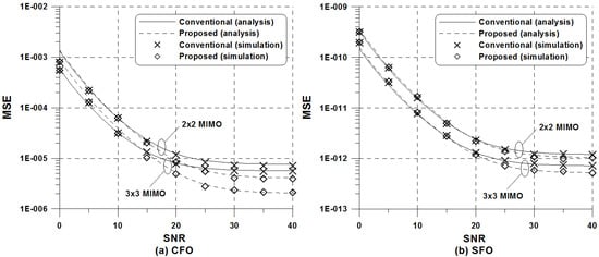
Figure 2.
MSE of the frequency-offset estimators in the ATSC 8 k mode when and ppm: (a) CFO estimation; (b) SFO estimation.
Figure 3 shows the MSE of the frequency-offset estimation schemes using 16k mode. At a high SNR regime, an irreducible MSE floor introduced by frequency-offset induced ICI is observed in the frequency estimation schemes. Because of the non-symmetrical distribution of CPs, the MSE performance of the conventional scheme using full CPs exhibits a severe error floor, which decreases with increasing , compared to that of the proposed scheme. Therefore, the pilot subset selection serves to remove a bias resulting from the use of randomly distributed CPs, and the MSE can be minimized by the proper selection of pilot subset. As expected in Equations (36) and (37), the detection ability can be enhanced with . Such physical behaviors is attributed to the fact that the use of multiple receive antennas increases the number of statistically independent observation samples used for frequency-offset estimation. More importantly, the performance gap between the conventional and proposed scheme becomes remarkable as increases.
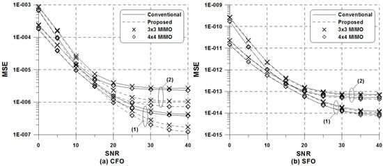
Figure 3.
MSE of the frequency-offset estimation schemes in the ATSC 16 k mode: (1) and ppm; (2) and ppm; (a) CFO estimation; (b) SFO estimation.
Figure 4 and Figure 5 present the MSE of the CFO detection methods for different values of frequency offsets when 8k and 16k modes are used, respectively. Here, the SNR was fixed at 30 dB. It is obvious from the figure that the increase in frequency offset induces a significant ICI as well as an additional bias in the case of the conventional scheme. More specifically, the increase in SFO heavily affects the MSE of the conventional scheme, whereas the proposed scheme turns out to be insensitive to the amount of SFO. For a wider fractional CFO range, it is also observed that theoretical analysis is in perfect agreement with simulated results. As predicted, the presence of multiple receive antennas enhances frequency-estimation performance due to inherent spatial diversity. In the case of the conventional scheme, the effect of receive diversity becomes outstanding for large values of CFO, whereas the same diversity effect of the proposed method is achieved regardless of the value of CFO in the case of the proposed scheme. Since CFO is very small during the tracking phase, the proposed estimation method is effective for MIMO-OFDM system and copes better with intrinsic ICI than the conventional method using full CPs.
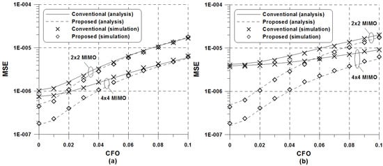
Figure 4.
MSE of the CFO estimators versus offsets in the ATSC 8 k mode when dB: (a) ppm; (b) ppm.
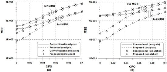
Figure 5.
MSE of the CFO estimators versus offsets in the ATSC 16 k mode when dB: (a) ppm; (b) ppm.
6. Conclusions
For reliable operation of OFDM systems, it is important to perform frequency-offset estimation robustly. Addressing this issue, this paper proposed an effective joint CFO and SFO estimation method in the ATSC system using MIMO-OFDM. For this purpose, a pilot subset selection was deployed on a per-subcarrier basis so that the proposed joint LSE was implemented in a decoupled way. To demonstrate the usefulness of the joint LSE approach, the MSE performance was numerically derived in a multipath fading channel considering the MIMO-OFDM context. By deriving a closed-form expression for the MSE of the frequency-offset estimate, it was shown the MIMO-OFDM ATSC system has a rich structural information to synchronize a system. The proposed joint estimation scheme that benefits from the optimal pilot subset was proven to be less affected by the amount of frequency offsets and to be computationally inexpensive, as compared to the conventional estimation scheme. Therefore, the proposed frequency-offset estimation scheme can be used to maximize the benefits of MIMO-OFDM in digital multimedia terrestrial broadcast systems. In future works, the presented theoretical analysis could be straightforwardly applied to other multimedia terrestrial broadcast systems. In addition, the performance of the MIMO-OFDM ATSC system under realistic channel conditions would reinforce the numerical analysis, particularly taking into account scenarios where the channels between transmit–receive antenna couples are correlated.
Author Contributions
Y.-A.J. developed the estimation method and conducted computer simulations. Y.-H.Y. analyzed the performance of the presented detection method and verified numerical results.
Funding
This research was supported by the Basic Science Research Program through the National Research Foundation of Korea (NRF) funded by the Ministry of Education (NRF-2018R1D1A1B07048819).
Conflicts of Interest
The authors declare no conflict of interest.
References
- Cvijetic, N. OFDM for next-generation optical access networks. J. Lightw. Technol. 2012, 30, 384–398. [Google Scholar] [CrossRef]
- Shimizu, S.; Cincotti, G.; Wada, N. Demonstration and performance investigation of all-optical OFDM systems based on arrayed waveguide gratings. Opt. Express 2012, 20, 525–534. [Google Scholar] [CrossRef] [PubMed]
- Arik, S.O.; Kahn, J.M.; Ho, K. MIMO signal processing for mode-division multiplexing: An overview of channel models and signal processing architectures. IEEE Signal Process. Mag. 2014, 31, 25–34. [Google Scholar] [CrossRef]
- Elbaz, D.; Malka, D.; Zalevsky, Z. Photonic crystal fiber based 1xN intensity and wavelength splitters/couplers. Electromagnetics 2012, 32, 209–220. [Google Scholar] [CrossRef]
- Vappangi, S.; Mani Vakamulla, V. Synchronization in visible light communication for smart cities. IEEE Sens. J. 2018, 18, 1877–1886. [Google Scholar] [CrossRef]
- ETSI ES 201 980 V4.1.1. Digital radio mondiale (DRM); System Specification. European Broadcasting Union. 2014. Available online: http://www.drm.org/ (accessed on 20 August 2018).
- ETSI EN 302 755 V.1.4.1. Digital video broadcasting (DVB); Frame Structure Channel Coding and Modulation for a Second Generation Digital Terrestrial Television Broadcasting System (DVB-T2). European Broadcasting Union. 2015. Available online: http://www.dvb.org/ (accessed on 20 August 2018).
- DVB Document A160. Digital Video Broadcasting, Next Generation Broadcasting System to Handheld, Physical Layer Specification (DVB-NGH). European Broadcasting Union. 2012. Available online: http://www.dvb.org/ (accessed on 20 August 2018).
- ITU-R. WP 11A/59. Channel Coding, Frame Structure and Modulation Scheme for Terrestrial Integrated Service Digital Broadcasting (ISDB-T). 1999. Available online: https://www.arib.or.jp/ (accessed on 20 August 2018).
- Document A/322. ATSC Standard: Physical Layer Protocol; Advanced Television Systems Committee: Washington, DC, USA, 2017; Available online: https://www.atsc.org/ (accessed on 20 August 2018).
- Hossen, M.S.; Kim, S.H.; Kim, K.D. Stereoscopic video transmission over DVB-T2 system using future extension frame. IEEE Trans. Broadcast. 2016, 62, 817–825. [Google Scholar]
- Gomez-Barquero, D.; Douillard, C.; Moss, P.; Mignone, V. DVB-NGH: The next generation of digital broadcast services to handheld devices. IEEE Trans. Broadcast. 2014, 60, 246–257. [Google Scholar] [CrossRef]
- Gomez-Barquero, D.; Vargas, D.; Fuentes, M.; Klenner, P.; Moon, S.; Choi, J.; Schneider, D.; Murayama, K. MIMO for ATSC 3.0. IEEE Trans. Broadcast. 2016, 62, 298–305. [Google Scholar] [CrossRef]
- Saito, S.; Shitomi, T.; Asakura, S.; Satou, A.; Okano, M.; Murayama, K.; Tsuchida, K. 8K terrestrial transmission field tests using dual-polarized MIMO and higher-order modulation OFDM. IEEE Trans. Broadcast. 2016, 62, 306–315. [Google Scholar] [CrossRef]
- Shitomi, T.; Garro, E.; Murayama, K.; Gomez-Barquero, D. MIMO scattered pilot performance and optimization for ATSC 3.0. IEEE Trans. Broadcast. 2018, 64, 188–200. [Google Scholar] [CrossRef]
- Vargas, D.; Kim, Y.; Bajcsy, J.; Gomez-Barquero, D.; Cardona, N. A MIMO-channel-precoding scheme for next generation terrestrial broadcast TV systems. IEEE Trans. Broadcast. 2015, 61, 445–456. [Google Scholar] [CrossRef]
- Speth, M.; Fechtel, S.A.; Fock, G.; Meyr, H. Optimum receiver design for wireless broad-band systems using OFDM-Part I. IEEE Trans. Commun. 1999, 47, 1668–1677. [Google Scholar] [CrossRef]
- Rotoloni, M.; Tomasin, S.; Vangelista, L. Maximum likelihood estimation of time and carrier frequency offset for DVB-T2. IEEE Trans. Broadcas. 2012, 58, 77–86. [Google Scholar] [CrossRef]
- Zhang, J.; Tian, L.; Wang, Y.; Liu, M. Selection transmitting/maximum ratio combining for timing synchronization of MIMO-OFDM systems. IEEE Trans. Broadcas. 2014, 60, 626–636. [Google Scholar] [CrossRef]
- Surantha, N.; Nagao, Y.; Kurosaki, M.; Ochi, H. Sampling frequency offset estimation for digital terrestrial television broadcasting system. IEICE Commun. Express 2013, 2, 224–230. [Google Scholar] [CrossRef]
- Fay, L.; Michael, L.; Gomez-Barquero, D.; Ammar, N.; Caldwell, M. An overview of the ATSC 3.0 physical layer specification. IEEE Trans. Broadcast. 2016, 62, 159–171. [Google Scholar] [CrossRef]
- Oberli, C. ML-based tracking algorithms for MIMO-OFDM. IEEE Trans. Wirel. Commun. 2007, 6, 2630–2639. [Google Scholar] [CrossRef]
- Jose, R.; Hari, K.V.S. Maximum likelihood algorithms for joint estimation of synchronisation impairments and channel in multiple input multiple output orthogonal frequency division multiplexing system. IET Commun. 2013, 7, 1567–1579. [Google Scholar] [CrossRef]
- Yuan, J.; Torlak, M. Joint CFO and SFO estimator for OFDM receiver using common reference frequency. IEEE Trans. Broadcast. 2016, 62, 141–149. [Google Scholar] [CrossRef]
- Kim, Y.H.; Lee, J.H. Joint maximum likelihood estimation of carrier and sampling frequency offsets for OFDM systems. IEEE Trans. Broadcast. 2013, 57, 277–283. [Google Scholar]
- Speth, M.; Fechtel, S.A.; Fock, G.; Meyr, H. Optimum receiver design for OFDM-based broadband transmission-Part II: a case study. IEEE Trans. Commun. 2001, 49, 571–578. [Google Scholar] [CrossRef]
- Shi, K.; Serpedin, E.; Ciblat, P. Decision-directed fine synchronization in OFDM systems. IEEE Trans. Commun. 2005, 53, 408–412. [Google Scholar] [CrossRef]
- Liu, S.; Chong, J.A. Study of joint tracking algorithms of carrier frequency offset and sampling clock offset for OFDM-based WLANs. In Proceedings of the International Conference on Communications, Circuits and Systems and West Sino Expositions, Chengdu, China, 29 June–1 July 2002. [Google Scholar]
- Tsai, P.Y.; Kang, H.Y.; Chiueh, T.D. Joint weighted least-squares estimation of carrier-frequency offset and timing offset for OFDM systems over multipath fading channels. IEEE Trans. Veh. Technol. 2005, 54, 211–223. [Google Scholar] [CrossRef]
- Chiang, P.H.; Lin, D.B.; Li, H.J.; Stuber, G.L. Joint estimation of carrier-frequency and sampling-frequency offsets for SC-FDE systems on multipath fading channels. IEEE Trans. Commun. 2008, 56, 1231–1235. [Google Scholar] [CrossRef]
- Lin, Y.T.; Chen, S.G. A blind fine synchronization scheme for SC-FDE systems. IEEE Trans. Commun. 2014, 62, 293–301. [Google Scholar] [CrossRef]
- Nguyen-Le, H.; Le-Ngoc, T.; Ko, C.C. Joint channel estimation and synchronization for MIMO-OFDM in the presence of carrier and sampling frequency offsets. IEEE Trans. Veh. Technol. 2009, 58, 3075–3081. [Google Scholar] [CrossRef]
- Morelli, M.; Moretti, M. Fine carrier and sampling frequency synchronization in OFDM systems. IEEE Trans. Wireless Commun. 2010, 9, 1514–1524. [Google Scholar] [CrossRef]
- Murin, Y.; Dabora, R. Low complexity estimation of carrier and sampling frequency offsets in burst-mode OFDM systems. Wireless Commun. Mob. Comput. 2016, 16, 1018–1034. [Google Scholar] [CrossRef]
- Jose, R.; Ambat, S.K.; Hari, K.V.S. Low complexity joint estimation of synchronization impairments in sparse channel for MIMO-OFDM system. Int. J. Electron. Commun. 2014, 68, 151–157. [Google Scholar] [CrossRef]
- Salari, S.; Heydarzadeh, M. Joint maximum-likelihood estimation of frequency offset and channel coefficients in multiple-input multiple-output orthogonal frequency-division multiplexing systems with timing ambiguity. IET Commun. 2011, 5, 1964–1970. [Google Scholar] [CrossRef]
- Yao, Y.; Giannakis, G.B. Blind carrier frequency offset estimation in SISO, MIMO, and multiuser OFDM systems. IEEE Trans. Commun. 2005, 53, 173–183. [Google Scholar] [CrossRef]
- Lin, T.T.; Hwang, F.H. On the CFO/Channel estimation technique for MIMO-OFDM systems without using a prior knowledge of channel length. EURASIP J. Wirel. Commun. Netw. 2015, 79, 1–13. [Google Scholar] [CrossRef]
- Salvo Rossi, P.; Romano, G.; Ciuonzo, D.; Palmieri, F. Gain design and power allocation for overloaded MIMO-OFDM systems with channel state information and iterative multiuser detection. In Proceedings of the 2011 International Symposium on Wireless Communication Systems, Aachen, Germany, 6–9 November 2011; pp. 769–773. [Google Scholar]
- Failli, M. COST 207: Digital Land Mobile Radio Communications; European Commission: Luxembourg, 1989. [Google Scholar]
© 2018 by the authors. Licensee MDPI, Basel, Switzerland. This article is an open access article distributed under the terms and conditions of the Creative Commons Attribution (CC BY) license (http://creativecommons.org/licenses/by/4.0/).