Article

Complexity Effective Sampling Frequency Offset Estimation Method for OFDM-Based HomePlug Green PHY Systems

Department of Computer Engineering, Sejong University, Gunja-dong 98, Gwangjin-gu, Seoul 05006, Korea
*
Author to whom correspondence should be addressed.
Symmetry 2018, 10(11), 544; https://doi.org/10.3390/sym10110544
Submission received: 15 October 2018 / Revised: 23 October 2018 / Accepted: 23 October 2018 / Published: 25 October 2018

Abstract

:
The HomePlug Green PHY (HomePlug GP) specification provides an attractive solution to enable smart grid power line communication (PLC) applications by using robust orthogonal frequency division multiplexing (ROBO) mode. This paper proposes a computationally efficient sampling frequency offset (SFO) estimation technique in the HomePlug GP system without relying on pilot symbols. For this purpose, the proposed estimation scheme utilizes the redundant information contained within the repeat coding in the HomePlug GP ROBO mode, thus eliminating the need of dedicated pilots. Computer simulations are conducted to assess the performance of the proposed SFO estimation scheme and to compare it with the conventional decision-directed (DD) estimation schemes. Simulations indicate that the repeat coded ROBO signals are effectively used for the proposed estimation scheme, which provides an affordable estimation accuracy while reducing the complexity compared to the conventional DD estimation schemes.

1. Introduction

Power line communication (PLC) technology has received significant attention as a highly competitive candidate for smart grid applications since the PLC infrastructure is already widely deployed and the use of the power line network for communication purposes does not demand any extra cost. Due to the rapid development of communication technology, the power line network is fully considered as high-speed data communication [1]. Though the high data rates are being achieved using other data networks, PLC network offers many attractive benefits of cost-effective access network installation using the pre-deployed electrical network infrastructure by which the network coverage can be widely extended to the remote areas. Recently, there is a trend towards deploying power lines as physical medium for data communication, which eliminates the need for dedicated communication links [2,3]. Since the power line network is not designed for data communication, PLC technology has some problems such as cable attenuation, narrowband interference, frequency-selective fading, and dynamic impedance across the network [4,5,6,7].
Orthogonal frequency division multiplexing (OFDM) has been widely used as a key transmission technology for narrowband and broadband communication over power lines. Recently, OFDM has been adopted by many industrial associations such as the high-definition power line communication (HD-PLC) alliance [8], the HomePlug powerline alliance (HPA) [9], and the universal powerline association (UPA) [10]. Among them, HomePlug Green PHY (HomePlug GP) is a new PLC technology for smart grid applications [11]. HomePlug GP is a low-rate version of the HomePlug AV standard with an emphasis on a robust communication, which is achieved by utilizing exclusively QPSK modulation and adopting robust OFDM (ROBO) modes. Specifically, ROBO mode is a form of repetition code and its throughput relies on the degree to which coding is repeated across streams. As in other communication systems, OFDM has been employed to effectively address the hardness of PLC channels because of its capability to mitigate frequency selectivity of the channel and to notch segment of the transmitted spectrum [12,13]. However, a potential drawback of OFDM is also inherent in the PLC applications. A widely known problem of OFDM is its vulnerability of the receiver to oscillator instabilities such as carrier frequency offset (CFO) and sampling frequency offset (SFO). Both CFO and SFO bring about inter-carrier interference (ICI) and inter-symbol interference (ISI), which may severely deteriorate system performance [14,15]. Therefore, it is crucial to keep the synchronization between the transmitter and the receiver. The frequency synchronization can be performed either by the use of pilot symbols or in a blind way [16,17,18,19,20,21,22,23,24,25]. Although maximum likelihood estimation (MLE) is known to provide optimal estimates of CFO and SFO, its complexity tends to be prohibitively expensive for use in practical systems [16,17,18,19]. In order to account for this issue, its low complexity versions have been investigated in many literature [20,21,22]. Commonly used synchronization algorithms take advantage of repetitive patterns of pilot symbols to estimate CFO and SFO [16,17,18,19,20,21,22]. However, a lot of pilot symbols should be embedded to help acquire synchronization in a time-variant PLC channel, leading to a decrease of the spectral efficiency. In indoor PLC environments, the decision-directed (DD) method is more appropriate than the pilot-assisted estimation method because the location of the notch in the channel frequency response (CFR) is unknown [23,24,25]. Besides some advantageous features, the DD method has a long processing delay and high computational burden due to tentative decoding.
To solve this problem, this paper proposes a computationally effective SFO estimation scheme for the OFDM-based HomePlug GP system, which does not require a priori knowledge on pilot symbols nor channel side information (CSI). The proposed estimation scheme exploits a repetition structure inherent in the HomePlug GP signal using repeat coding, thus removing the use for decided data or dedicated pilots. To accommodate to the tone mask requirement, the proposed frequency-offset estimation scheme considers the concept of carrier grouping together. The mean square error (MSE) is theoretically derived to verify the feasibility of the proposed estimation scheme. We demonstrate from simulation results that the proposed estimation scheme with repeat coding and subcarrier grouping achieves accurate synchronization and relieves the computational burden.
The outline of the paper is as follows. Section 2 presents the signal model in the baseband PLC system using ROBO scheme. In Section 3, we briefly introduce the existing SFO estimation algorithms, having some limitations when applied to the HomePlug system. In Section 4, a complexity effective SFO estimation scheme is proposed using inherent redundant information in the HomePlug GP signal. Section 5 presents the simulation results proving the effectiveness of the proposed SFO estimation scheme. Section 6 concludes this paper.

2. Signal Model

Let us consider an OFDM signal using N b subcarriers. By using N-point inverse fast Fourier transform (IFFT) on the information symbols, the frequency-domain signal is transformed into the time domain. To remove ISI, a cyclic prefix (CP) with length N g samples is appended to the beginning of each OFDM symbol to form an OFDM symbol. Since HomePlug GP is based on baseband OFDM transmission, there is no RF modulator and demodulator. For this reason, we can completely ignore the CFO. In a baseband PLC system using OFDM, synchronization process can be divided into a initial acquisition stage and a fine tracking stage. The symbol timing synchronization for pre-FFT removal of CP is performed during the acquisition step. The primary goal of fine tracking step is to handle fine symbol timing estimation and SFO tracking (post-FFT synchronization). To restrict our attention here to the estimation of SFO, it is assumed that the symbol timing offset is perfectly compensated at the receiver. In the HomePlug GP system, it is reasonable to assume a zero CFO scenario because the signal is transmitted directly without carrier modulation [25,26]. Generally, SFO Δ s will be relatively small during the tracking stage. Let Δ s be the normalized SFO by the sampling rate f s = 1 / T s .
The received frequency-domain OFDM symbol during the l-th period can be described as former works [16,17]
R l ( k ) = α ( ϕ ( k ) ) H l ( k ) X l ( k ) e j 2 π ϕ ( k ) ( l N u + N g ) / N e j π ( N 1 ) ϕ ( k ) / N + I l ( k ) + Z l ( k ) , 0 k < N b
where ϕ ( k ) = k Δ s considering the baseband PLC scenarios, α ( ϕ ( k ) ) = sin ( π ϕ ( k ) / N sin ( π ϕ ( k ) / N ) stands for the magnitude attenuation introduced by ϕ ( k ) , N u = N + N g , N b N / 2 , H l ( k ) means a zero-mean CFR with variance σ H 2 in the l-th symbol period, Z l ( k ) is a zero-mean Gaussian noise with variance σ Z 2 , and I l ( k ) is the SFO-induced ICI with variance σ I 2 written by
I l ( k ) = n = 0 , n k N 1 H l ( n ) X l ( n ) e j 2 π ϕ ( n ) ( l N u + N g ) / N α ( ϕ ( n ) + n k ) e j π ( N 1 ) ( ϕ ( n ) + n k ) N .
During the tracking phase, SFO is small enough that α ( ϕ ( k ) ) 1 .
HomePlug GP standard includes three ROBO modes, namely, standard ROBO mode, high-speed ROBO mode, and mini ROBO mode [11], which is summarized in Table 1. The HomePlug GP employs special interleaver for the ROBO modes, whose throughput depends on the degree of an outer repetition code. It supports a maximum PHY rate of 10 Mbps over severely impaired PLC channels. A diversity copier maps the 256 interleaved bits for QPSK mapping onto non-masked carriers so that each bit is duplicated at least 2 times, relying on the degree of repetition code. Besides, a HomePlug GP terminal shall be able to support tone masks of any combination of unmasked carriers within frequency range of 1.8∼30 MHz. Thus, the synchronization receiver must be able to accommodate the spectral mask requirements of the region or application.

3. Conventional SFO Estimation Scheme

Post-FFT synchronization strategies can be practically implemented by performing correlation between dedicated pilots of successive OFDM symbols in the frequency domain [16,17,18,19,20,21,22]. In contrast, the DD estimation scheme is proposed to find the phase rotation of the OFDM signal caused by the frequency offset without relying on a dedicated pilot. To do this, a priori knowledge of the transmitted data is of paramount importance [23,24]. The DD estimation scheme spends a large number of complex multiplications in comparison to the pilot-based estimation scheme. Although the latter is too computationally demanding, it can be considered as a promising candidate for the estimation strategy rather than the pilot-based estimation scheme because the Homeplug GP system contains no dedicated pilot symbols for synchronization. Hereafter, we limit our study to the DD estimation strategy.

3.1. Conventional Scheme A

From previous work [23], we consider the post-FFT correlation between two OFDM symbols at subcarrier k i , which is given by
Λ m = i = 1 N c / 2 R ^ l * ( k i + ( m 1 ) N / 2 ) R ^ l + D ( k i + ( m 1 ) N / 2 ) , m = 0 , 1
with
R ^ l * ( k i ) = R l ( k i ) / X ^ l ( k i ) = H l ( k i ) e j 2 π ϕ ( k i ) ( l N u + N g ) / N e j π ( N 1 ) ϕ ( k i ) / N + I l ( k i ) / X ^ l ( k i ) + Z l ( k i ) / X ^ l ( k i ) + ϵ l ( k i )
where N c is the number of non-masked carriers used for data transmission, k i is the subcarrier index of the i-th non-masked carrier, X ^ l ( k i ) is the decided data symbol in subcarrier k i , D is the time separation between the OFDM symbols, and ϵ l ( k i ) is the decision error given by
ϵ l ( k i ) = H l ( k i ) X l ( k i ) X ^ l ( k i ) X ^ l ( k i ) e j 2 π ϕ ( k i ) ( l N u + N g ) / N e j π ( N 1 ) ϕ ( k i ) / N .
When the additive noise is very large, the phase difference between two OFDM symbols is relatively small, which leads to poor frequency-offset estimation. To resolve this problem, D-symbol delay estimation is a promising strategy as adopted in (3). To obtain X ^ l ( k ) , we can use simple hard data decision. Practically, it is reasonable to use the hard decision as discussed in former work [23]. By using two consecutive data-recovered OFDM symbols, the basic DD concept can be extended to the OFDM-based PLC system. The estimate of Δ s is then obtained as
Δ ^ s = N 2 π N u arg { Λ 2 } arg { Λ 1 } k N / 2 + 1 k 1
where arg { x } denotes the angle of a complex number x. As discussed [23], Equation (6) provides an unbiased estimate in the presence of small SFO. More importantly, the unbiasedness of Equation (6) holds true when the subcarriers used for estimation have a symmetric and uniform distribution around the DC carrier. However, this condition is no longer met depending on the transmit spectrum mask, which results in biased estimates.

3.2. Conventional Scheme B

The main idea in former work [24] can be also applied to the HomePlug GP system in a DD manner. Since the HomePlug GP system is proposed as a baseband transmission scheme, only positive subcarriers are available in data decoding. Therefore, the estimated SFO is obtained by
Δ ^ s = N 2 π N u i = 1 N c k i | H l ( k i ) | 2 arg { R ^ l * ( k i ) R ^ l + D ( k i ) } i = 1 N c k i 2 | H l ( k i ) | 2
which is also based on the received data-recovered OFDM symbol R ^ l * ( k i ) . The estimation scheme Equation (7) spends more arctangent calculations with a performance superior to Equation (6). Since the performance of the DD estimation strategy depends heavily on the accuracy of symbol decision after equalization, the quality of channel estimation has a significant influence on the estimation accuracy. Therefore, it makes the DD scheme difficult to apply in a severely frequency-selective PLC channel.

3.3. Conventional Scheme C

In previous work [22], the frequency error ϕ ( k i ) can be get by using the g-lag correlation. Denote N o as the number of observed OFDM blocks. Based on N o blocks, the g-lag correlation at subcarrier k i takes the form
Λ g ( k i ) = l = g + 1 N o R ^ l ( k i ) R ^ l g * ( k i ) , 1 g < N o .
Its application to the PLC system with N o observed OFDM blocks leads to
ϕ ^ ( k i ) = N 2 π N u g = 1 N o / 2 p ( g ) arg Λ g ( k i ) Λ g 1 * ( k i )
where { p ( g ) } represents the weighting coefficients. By using ϕ ^ ( k i ) , an estimate of Δ s is computed as
Δ ^ s = J ( 1 ) B ( 2 ) J ( 2 ) B ( 1 ) J ( 1 ) J ( 3 ) J 2 ( 2 )
where
J ( n ) = 1 N c i = 1 N c k i n 1 | H l ( k i ) | 2 , n = 1 , 2 , 3
and
B ( n ) = 1 N c i = 1 N c k i n 1 | H l ( k i ) | 2 ϕ ^ ( k i ) , n = 1 , 2 .
Note that this scheme depends on some information about the channel statistics such as the quantities J ( n ) and B ( n ) , and still demands heavy computational complexity.

4. Proposed SFO Estimation Scheme

In this section, we develop an effective frequency-offset estimation scheme that does not rely on any information about the channel and training symbols in the HomePlug GP system. By using a repeat coding specified in the HomePlug GP standard, the symbol at the k-th subcarrier through the ROBO interleaver is duplicated to the subcarrier spaced by F m , where F m is the distance between two data subcarriers copied by cyclic shift at the m-th subset. To accommodate to tone mask requirements, the proposed estimation scheme utilizes the concept of carrier grouping in the computation of frequential correlation. In the proposed approach, N c non-masked subcarriers are grouped into a number of subsets, so that two repeated replicas have an unique distance F m . Therefore, the m-th subset contains the elements of twin data that are separated by F m subcarriers.

4.1. Estimation Algorithm

The presence of unknown X l ( k ) and H l ( k ) may make accurate SFO estimation difficult. To solve for this problem, the proposed frequency estimation scheme adopts two-step correlation, namely temporal correlation and frequential correlation, which are used to eliminate the use of CSI and dedicated pilots, respectively. First, to cancel out influence of X l ( k ) without decoding it, we utilizes the fact that each non-masked subcarrier forms at least one pair of subcarriers satisfying X l ( k ) = X l ( k + F m ) in the HomePlug ROBO mode, leading to X l * ( k ) X l ( k + F m ) = | X l ( k ) | 2 . By using this property of the repetition code, the frequential correlation C l ( k ) is constructed by
C l ( k ) = R l * ( k ) R l ( k + F m ) , m = 1 , 2 , , N s , k S m
where N s is the number of subsets containing distinctive F m ’s, S m is the m-th subset of the first data subcarriers among two same data spaced F m subcarriers apart, and k S m means the data subcarrier in the m-th subset. Recognizing that X l * ( k ) X l ( k + F m ) = | X l ( k ) | 2 , C ^ l ( k ) is further derived as
C l ( k ) = H l * ( k ) H l ( k + F m ) | X l ( k ) | 2 e j 2 π F m Δ s ( l N u + N g ) / N + I ^ l ( k ) + Z ^ l ( k )
where I ^ l ( k ) stands for the combined ICI given by
I ^ l ( k ) = H l * ( k ) X l * ( k ) I l ( k + F m ) e j 2 π ϕ ( k + F m ) ( l N u + N g ) / N + H l ( k + F m ) X l ( k + F m ) I l * ( k ) e j 2 π ϕ ( k ) ( l N u + N g ) / N + I l ( k + F m ) Z l * ( k ) + I l * ( k ) Z l ( k + F m ) + I l ( k + F m ) I l * ( k ) ,
and Z ^ l ( k ) represents the AWGN given by
Z ^ l ( k ) = H l * ( k ) X l * ( k ) Z l ( k + F m ) e j 2 π ϕ ( k + F m ) ( l N u + N g ) / N + H l ( k + F m ) X l ( k + F m ) Z l * ( k ) e j 2 π ϕ ( k ) ( l N u + N g ) / N + Z l ( k + F m ) Z l * ( k ) .
The second step is employed to remove the need for an estimated channel. For this purpose, we use the following temporal correlation
C ˜ l ( k ) = C l * ( k ) C l + D ( k )
where we can make a reasonable assumption that H l ( k ) = H l + D ( k ) thanks to the characteristics of indoor PLC channels [5,13]. Then, C ˜ l ( k ) can be expressed by
C ˜ l ( k ) = | H l ( k ) | 2 | H l ( k + F m ) | 2 | X l ( k ) | 2 | X l + D ( k ) | 2 e j 2 π F m D Δ s N u / N + I ˜ l ( k ) + Z ˜ l ( k ) , m = 1 , 2 , , N s
where
I ˜ l ( k ) = H l ( k ) H l * ( k + F m ) I ^ l + D ( k ) | X l ( k ) | 2 e j 2 π F m Δ s ( l N u + N g ) / N + H l + D * ( k ) H l + D ( k + F m ) I ^ l * ( k ) | X l + D ( k ) | 2 e j 2 π F m Δ s ( ( l + D ) N u + N g ) / N + I ^ l * ( k ) Z ^ l + D ( k ) + Z ^ l * ( k ) I ^ l + D ( k ) + I ^ l * ( k ) I ^ l + D ( k )
and
Z ˜ l ( k ) = H l ( k ) H l * ( k + F m ) Z ^ l + D ( k ) | X l ( k ) | 2 e j 2 π F m Δ s ( l N u + N g ) / N + H l + D * ( k ) H l + D ( k + F m ) Z ^ l * ( k ) | X l + D ( k ) | 2 e j 2 π F m Δ s ( ( l + D ) N u + N g ) / N + Z ^ l * ( k ) Z ^ l + D ( k ) .
From former work [22], I l ( k ) can be treated as zero-mean Gaussian noise with variance σ I 2 . Since E { I ^ l ( k ) } = E { Z ^ l ( k ) } = 0 , it immediately follows from Equations (19) and (20) that E { I ˜ l ( k ) } = E { Z ˜ l ( k ) } = 0 . Thus, it turns out to be
arg E C ˜ l ( k ) = 2 π F m D Δ s N u / N
where E { x } is the expectation of x. It is evident from Equation (21) that the estimation performance is proportional to the number of statistically significant correlation samples C ˜ l ( k ) for m’s and k’s.
For subcarrier pairs having the same F m , the block-wise partial correlation can be obtained as
Ω m = k S m C ˜ l ( k ) , m = 1 , 2 , , N s
where the number of subcarriers assigned in S m is denoted by N m . Eventually, an estimate of Δ s is derived by finding the argument of Ω m over all possible m’s, which takes expression
Δ ^ s = 1 N s m = 1 N s N 2 π F m D N u arg Ω m
or equivalently
Δ ^ s = 1 N s m = 1 N s N 2 π F m D N u tan 1 Ω m Ω m
where tan 1 { · } is the arctangent function, and { x } and Im { x } are the real and imaginary parts of a complex number x, respectively. Note that the parameters F m and N s depend on the transmit spectrum mask that defines the set of tones.

4.2. MSE Analysis

This section derives the MSE expression of the proposed estimation scheme presented in Equation (24). By denoting υ = e j 2 π F m D Δ s N u / N , it is found from Equation (24) that the argument of the phase-rotated partial correlation Ω m υ can be written as
tan 1 Ω m υ Ω m υ = tan 1 Ω m Ω m + tan 1 { e j 2 π F m D Δ s N u / N } = 2 π F m D N u / N ( Δ ^ s Δ s )
for m = 1 , 2 , , N s . Since Δ ^ s Δ s for high signal-to-noise ratio (SNR), it is obvious from Equation (25) that
Ω m υ Ω m υ = tan 2 π F m D N u / N ( Δ ^ s Δ s ) 2 π F m D N u / N ( Δ ^ s Δ s ) .
Under the high SNR assumption [27], it can be safely assumed that
Ω m υ k S m I ˜ l ( k ) + Z ˜ l ( k ) υ .
With this assumption in mind, the denominator of the left-hand side (LHS) of Equation (26) is well approximated by
Ω m υ k S m | H l ( k ) | 2 | H l ( k + F m ) | 2 | X l ( k ) | 2 | X l + D ( k ) | 2 .
For relatively large N m and frequency selectivity, one can make the useful approximation
Ω m υ N m E { | H l ( k ) | 2 } E { | H l ( k + F m ) | 2 } E X 2
where E X = | X l ( k ) | 2 = | X l + D ( k ) | 2 . Plugging Equation (29) into (26) produces
Δ ^ s Δ s N 2 π F m D N u Ω m υ N m σ H 4 E X 2 , m = 1 , 2 , , N s
where σ H 2 = E { | H l ( k ) | 2 } = E { | H l ( k + F m ) | 2 . Since E { Z ˜ l ( k ) } = E { I ˜ l ( k ) } = 0 , the mean and variance of Ω m υ are respectively calculated by
E Ω m υ = E k S m C ˜ l ( k ) υ = k S m E I ˜ l ( k ) υ + Z ˜ l ( k ) υ = 0
and
σ 2 = N m E I ˜ l ( k ) υ + Z ˜ l ( k ) υ 2 = N m σ H 4 E X 2 σ I ^ 2 + σ I ^ 2 σ Z ^ 2 + σ I ^ 2 2 + N m σ H 4 E X 2 σ Z ^ 2 + σ Z ^ 4 2
where σ I ^ 2 is the variance of Equation (15) calculated by σ I ^ 2 = 2 σ H 2 E X σ I 2 + 2 σ I 2 σ Z 2 + σ I 4 and σ Z ^ 2 is the variance of Equation (16) given by σ Z ^ 2 = 2 σ H 2 E X σ Z 2 + σ Z 4 . From Equation (2), σ I 2 can be calculated by
σ I 2 = σ H 2 E X n = 0 , n k N 1 sin 2 ( π ( ϕ ( n ) + n k ) N 2 sin 2 ( π ( ϕ ( n ) + n k ) / N ) .
Using first order Taylor series of each term in summation in Equation (33) with respect to n k , we have
σ I 2 σ H 2 E X n = 0 , n k N 1 π 2 ϕ 2 ( n ) N 2 sin 2 ( π ( n k ) / N ) = σ H 2 E X Δ s 2 n = 0 , n k N 1 π 2 n 2 N 2 sin 2 ( π ( n k ) / N )
which says that σ I 2 in the presence of a typical values of Δ s is very small in comparison to σ Z 2 [14]. Therefore, the first term of the LHS of Equation (32) can be omitted. With those implications in mind, we obtain the MSE from Equation (30)∼ Equation (32)
E | Δ ^ s Δ s | 2 = 1 N s 2 m = 1 N s N 2 4 π 2 F m 2 D 2 N u 2 N m σ Z ^ 2 σ H 4 E X 2 1 + σ Z ^ 2 2 σ H 4 E X 2
which can be further expressed as
E | Δ ^ s Δ s | 2 = 1 N s 2 m = 1 N s N 2 2 π 2 F m 2 D 2 N u 2 N m 1 γ + 1 2 γ 2 1 + 1 γ + 1 2 γ 2
where γ = σ H 2 E X / σ Z 2 is the average SNR. It is obvious from Equation (36) that the choice of some design parameters D, N s , F m , and N m has a significant impact on estimation performance. Once the time separation D is determined to be used for synchronization, the parameters N s , F m , and N m are optimized by means of the subset selection considering tone mask requirements.

4.3. Complexity

To make a fair comparison between the conventional and proposed frequency estimation schemes, the computational complexity is defined as as the number of real floating point operations (flops) used to perform one-shot estimation. For this purpose, we count a complex multiplication as six flops, whereas a complex addition as two flops [28]. At the receiver, the frequency-domain equalization (FEQ) used to obtain X ^ l ( k ) is assumed to be already executed so that the complexity of the conventional estimation schemes is analyzed in the case of known CSI. Calculating Λ m in Equation (3) for m = 0 , 1 needs 20 N c 4 flops since QPSK modulation is used. Finally, two flops are additionally needed to acquire the SFO estimate Δ ^ s in Equation (6). Thus, the total computational complexity used in the conventional estimation scheme A is 20 N c 2 . Meanwhile, the total number of flops used in the conventional schemes B and C are 29 N c 2 and N c ( 12 N o 2 13 N o + 98 ) / 2 + 7 , respectively. In the proposed approach, taking the frequential correlation C l ( k ) in Equation (13) needs 3 N c flops, whereas 3 N c flops are additionally involved to compute the temporal correlation C ˜ l ( k ) in Equation (17). In order to obtain block-wise partial correlation Equation (22), 2 m = 1 N s N m 2 N s flops are needed, which is equal to N c 2 N s . Lastly, 2 N s 1 flops are required to get the SFO estimate Δ ^ s in Equation (23). The total number of flops of the proposed estimation scheme is counted as 7 N c 1 for each estimate.

5. Simulation Results and Discussions

The simulations have been conducted to verify the usefulness of the proposed estimation scheme, considering the standard ROBO and high-speed ROBO modes. In our simulations, the HomePlug GP system is operated at 1.8∼30 MHz frequency band. We use the main system parameters such as N = 3072 , N g = 417 , N b = 1155 , and N c = 916 carriers distributed in the frequency from approximately 1.8 MHz to 30 MHz. Table 2 summarizes the simulation parameters used in the experiment. To show the performance, the PLC channel model specified in the standard [29] is considered. Especially, Class 1 channel model is used, which represents scenarios with strong signal attenuation. To estimate the channel, a simple least square (LS) channel estimation followed by a one-tap FEQ is used for the conventional DD schemes. To make a fair comparison, the conventional estimation scheme C considers N o = D + 1 = 4 so that it uses four consecutive OFDM blocks.
To fully implement Equation (23), we have to know the subset configuration consisting of F m and N m , which is determined depending on the system parameters and tone mask. Taking into account the North American carrier mask and the OFDM parameters specified in the ROBO modes [11], one can obtain that N s = 11 for standard ROBO mode and N s = 10 for high-speed ROBO mode. It is interesting to note that there are two or more subset configurations because the data symbol is repeated four times in standard ROBO mode. In this case, the subset configuration having the optimal MSE is selected. Table 3 lists the basic design parameters of the subset searched for each ROBO mode.
In Figure 1, we compare the proposed scheme with three conventional DD schemes presented in Equations (6), (7), and (10) when Δ s = 15 ppm. For the sake of fairness, LS channel estimation scheme is adopted to compute (4) and the same channel estimate is used for Equations (6), (7), and (10). It is evident that there is a good match between theoretical analysis and simulated results. From the figure, one can find that the conventional schemes A and B have a non-negligible bias for high SNR condition, which is attributed to the reason that the frequency selectivity of the channel considerably affects the estimation performance as former work [23]. Unlike the conventional methods A and B, the effect of the frequency selectivity on the performance of the proposed scheme and the conventional scheme C is marginal. Since the conventional scheme C spends more OFDM blocks for estimation, its performance is slightly better than that of the proposed estimation scheme. Regardless of the ROBO mode, the performance of existing schemes is almost the same because they perform on carrier-by-carrier basis. On the other hand, the performance of the proposed scheme depends on the ROBO mode, which is mainly because of the different subset configurations as given in Table 2. In this example, the performance of the standard ROBO mode is about 2 dB better than that of the high-speed ROBO mode.
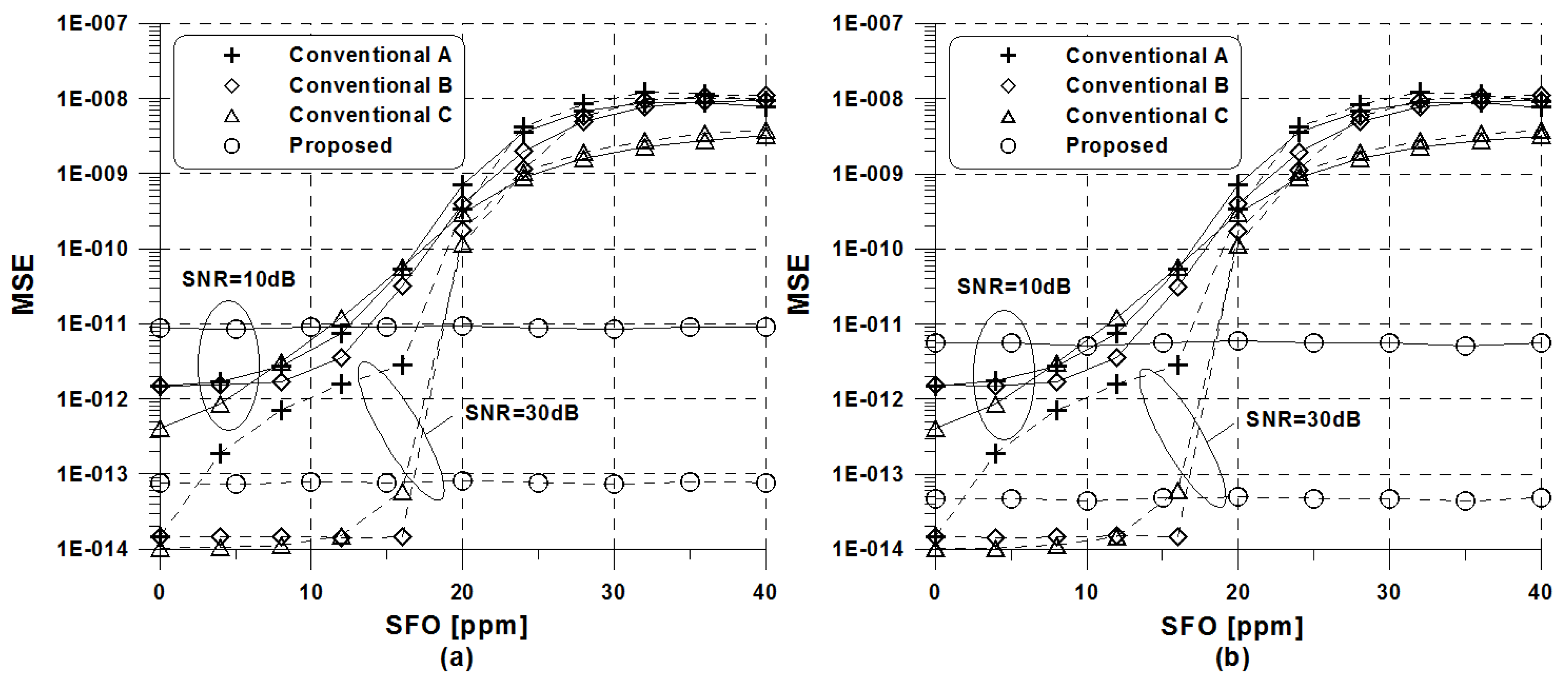
Figure 2 illustrates the MSE curves between the existing and proposed estimation schemes versus SFO values. It is found that the performance of the conventional schemes A and B strongly relies on the amount of SFO. The performance of the conventional method C keeps stable about up to Δ s = 15 ppm, whereas the proposed estimation algorithm shows a substantial robustness against the amount of SFO regardless of ROBO modes and SNR values. This phenomenon means that the existing estimation schemes will experience an error floor due to SFO as SNR grows. As discussed in Figure 1, the performance gap between the proposed scheme and the conventional scheme C can be observed within the range of Δ s < 15 ppm, because the proposed scheme adopts D-symbol delay estimation using only two OFDM symbols. Regarding the number of flops, the complexity of the proposed frequency-offset estimation scheme is significantly decreased by 65% and 75.9% in comparison to that used in the existing schemes A and B, respectively, whereas a 94.1% complexity saving over the conventional scheme C is obtained.
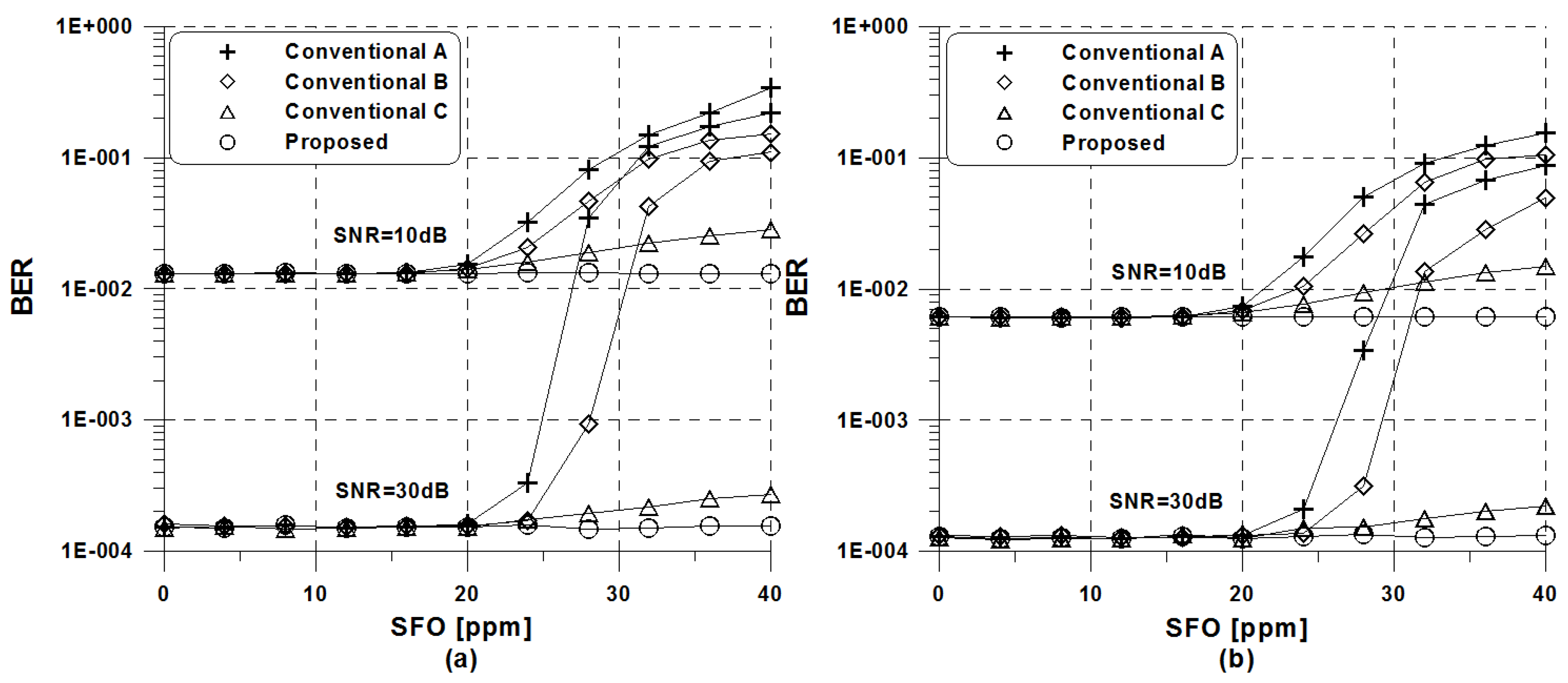
The uncoded bit error rate (BER) of the conventional and proposed estimation schemes versus SFO values is presented in Figure 3. Since we here focus on SFO estimation, a simple one-tap FEQ is adopted. We consider the situation where the received OFDM symbols are directly compensated in frequency domain once the SFO estimate is obtained every N o symbol periods. The relative performance of the conventional and proposed methods is shown to be similar to that discussed in Figure 2. It is clear that the conventional schemes can have approximately the same BER performance as the proposed scheme within the range of Δ s < 20 ppm. More importantly, the proposed frequency-offset estimation scheme shows a strong insensitivity to the amount of SFO, whereas all conventional schemes suffer significant performance degradation at 20 ppm or higher. As predicted, the repeat coding enhances the frequency-offset estimation performance thanks to inherent frequency-diversity gain.

6. Conclusions

To fully obtain the advantageous features of OFDM in the HomePlug GP system, it is very important to maintain the frequency synchronization between the transmitter and the receiver. To address this issue, this paper proposed an efficient SFO estimation scheme in the OFDM-based HomePlug GP system without resorting to pilot symbols. To enable pilot-less estimation of SFO, the proposed estimation scheme was designed to use a repetitive structure due to the redundant repetition coding adopted in the HomePlug ROBO mode. The subset selection according to tone mask requirements played an important part on minimizing an error floor from the presence of SFO and making the estimation scheme to be less computationally intensive. In order to verify the feasibility of the proposed scheme, the MSE is numerically derived. We have demonstrated from simulation and analytical results that the proposed estimation scheme reduces the computational burden and offers greater immunity to SFO in comparison to the conventional DD estimation methods. The HomePlug GP signal was proven to contain rich structural information for synchronizing systems without any need for dedicated pilots. For future works, the closed-form of the MSE could be straightforwardly extended to other PLC systems. Additionally, the performance of the OFDM HomePlug system under realistic indoor channel conditions would strengthen the theoretical analysis, especially considering the long-term and short-term time-varying nature of the PLC channel.

Author Contributions

Y.-A.J. and Y.-H.Y. designed the proposed estimation algorithm. Y.-A.J. supplemented the proposed algorithm. Y.-H.Y. gave feedbacks about an enhanced algorithm and all simulation results. Y.A.-J. and Y.-H.Y. wrote the paper jointly.

Funding

This research was supported by Basic Science Research Program through the National Research Foundation of Korea(NRF) funded by the Ministry of Education(NRF-2018R1D1A1B07048819).

Acknowledgments

We would like to thank the anonymous referees and editors for their careful reading on the manuscript and providing constructive comments.

Conflicts of Interest

The authors declare no conflict of interest.

References

  1. Ferreira, H.C.; Lampe, L.; Newbury, J.; Swart, T.G. Power Line Communications: Theory and Applications for Narrowband and Broadband Communications Over Power Lines; Wiley: Chichester, UK, 2010. [Google Scholar]
  2. Galli, S.; Scaglione, A.; Wang, Z. For the grid and through the grid: The role of power line communications in the smart grid. Proc. IEEE 2011, 6, 998–1027. [Google Scholar] [CrossRef]
  3. Lampe, L.; Tonello, A.M.; Swart, T.G. Power Line Communications: Principles, Standards and Applications from Multimedia to Smart Grid; Wiley: Chichester, UK, 2016. [Google Scholar]
  4. Katayama, M.; Yamazato, T.; Okada, H. A mathematical model of noise in narrowband power line communication systems. IEEE J. Sel. Areas Commun. 2006, 7, 1267–1276. [Google Scholar] [CrossRef]
  5. Marrocco, G.; Statovci, D.; Trautmann, S. A PLC broadband channel simulator for indoor communications. In Proceedings of the IEEE International Symposium on Power Line Communications and Its Applications, Johannesburg, South Africa, 24–27 March 2013; pp. 321–326. [Google Scholar]
  6. Taherinejad, N.; Rosales, R.; Lampe, L.; Mirabbasi, S. Channel characterization for power line communication in a hybrid electric vehicle. In Proceedings of the IEEE International Symposium on Power Line Communications and Its Applications, Beijing, China, 27–30 March 2012; pp. 328–333. [Google Scholar]
  7. Amrani, O.; Rubin, A. Contention detection and resolution for multiple-access power-line communications. IEEE Trans. Veh. Technol. 2007, 6, 3879–3887. [Google Scholar] [CrossRef]
  8. The HD-PLC Alliance Home Page. Available online: http://www.hd-plc.org (accessed on 1 June 2018).
  9. The HomePlug Powerline Alliance Home Page. Available online: http://www.homeplug.org (accessed on 1 June 2018).
  10. The Universal Powerline Association Home Page. Available online: http://www.upaplc.org (accessed on 1 June 2018).
  11. HomePlug Powerline Alliance, Inc. Homeplug Green PHY Specification Release Version 1.1.1; HomePlug Alliance: Portland, OR, USA, 2013. [Google Scholar]
  12. Sharma, K.; Saini, L.M. Power-line communications for smart grid: Progress, challenges, opportunities and status. Renew. Sustain. Energy Rev. 2017, 67, 704–751. [Google Scholar] [CrossRef]
  13. Cortés, J.; Díez, L.; Cañete, F.; Sánchez-Martínez, J.; Entrambasaguas, J. Performance analysis of OFDM modulation on indoor broadband PLC channels. EURASIP J. Adv. Signal Process. 2011, 78, 1–2. [Google Scholar] [CrossRef]
  14. Speth, M.; Fechtel, S.A.; Fock, G.; Meyr, H. Optimum receiver design for wireless broad-band systems using OFDM-Part I. IEEE Trans. Commun. 1999, 11, 1668–1677. [Google Scholar] [CrossRef]
  15. Chin, W.L. ML estimation of timing and frequency offsets using distinctive correlation characteristics of OFDM signals over dispersive fading channels. IEEE Trans. Veh. Technol. 2011, 2, 444–456. [Google Scholar] [CrossRef]
  16. Speth, M.; Fechtel, S.A.; Fock, G.; Meyr, H. Optimum receiver design for OFDM-based broadband transmission-Part II: A case study. IEEE Trans. Commun. 2001, 49, 571–578. [Google Scholar] [CrossRef]
  17. Oberli, C. ML-based tracking algorithms for MIMO-OFDM. IEEE Trans. Wirel. Commun. 2007, 7, 2630–2639. [Google Scholar] [CrossRef]
  18. Yuan, J.; Torlak, M. Joint CFO and SFO estimator for OFDM receiver using common reference frequenc. IEEE Trans. Broadcast. 2016, 62, 141–149. [Google Scholar] [CrossRef]
  19. Kim, Y.; Lee, J. Joint maximum likelihood estimation of carrier and sampling frequency offsets for OFDM systems. IEEE Trans. Broadcast. 2013, 57, 277–283. [Google Scholar]
  20. Tsai, P.Y.; Kang, H.Y.; Chiueh, T.D. Joint weighted least-squares estimation of carrier-frequency offset and timing offset for OFDM systems over multipath fading channels. IEEE Trans. Veh. Technol. 2005, 1, 211–223. [Google Scholar] [CrossRef]
  21. Chiang, P.; Lin, D.; Li, H.; Stuber, G.L. Joint estimation of carrier-frequency and sampling-frequency offsets for SC-FDE systems on multipath fading channels. IEEE Trans. Commun. 2008, 56, 1231–1235. [Google Scholar] [CrossRef]
  22. Morelli, M.; Moretti, M. Fine carrier and sampling frequency synchronization in OFDM systems. IEEE Trans. Wirel. Commun. 2010, 4, 1514–1524. [Google Scholar] [CrossRef]
  23. Shi, K.; Serpedin, E.; Ciblat, P. Decision-directed fine synchronization in OFDM systems. IEEE Trans. Commun. 2005, 3, 408–412. [Google Scholar] [CrossRef]
  24. Lin, Y.; Chen, S. A blind fine synchronization scheme for SC-FDE systems. IEEE Trans. Commun. 2014, 62, 293–301. [Google Scholar] [CrossRef]
  25. Lalos, A.; Vgenis, A.; Gioulekas, F.; Birbas, M. Pilot-less time synchronization for OFDM systems: Application to power line receivers. Int. J. Distrib. Sens. Netw. 2016, 12, 1–12. [Google Scholar] [CrossRef]
  26. Kim, Y.H.; Lee, J.H. Comparison of passband and baseband transmission schemes for power-line communication OFDM systems. IEEE Trans. Power Deliv. 2011, 4, 2466–2475. [Google Scholar] [CrossRef]
  27. Fowler, M. Phase-based frequency estimation: A review. Digit. Signal Process. 2002, 4, 590–615. [Google Scholar] [CrossRef]
  28. Golub, G.H.; Vanloan, C.F. Matrix Computations; The Johns Hopkins University Press: Baltimore, MA, USA, 1996. [Google Scholar]
  29. Tonello, A.M.; D’Alessandro, S.; Lampe, L. Cyclic prefix design and allocation in bit-loaded OFDM over power line communication channels. IEEE Trans. Commun. 2010, 58, 3265–3276. [Google Scholar] [CrossRef]
Figure 1. Mean square error (MSE) comparison between the proposed and conventional estimation schemes versus signal to noise ratio (SNR): (a) High-speed robust orthogonal frequency division multiplexing (ROBO) mode (b) Standard ROBO mode.
Symmetry 10 00544 g001
Figure 2. MSE comparison between the proposed and conventional estimation schemes versus sampling frequency offset (SFO): (a) High-speed ROBO mode (b) Standard ROBO mode.
Symmetry 10 00544 g002
Figure 3. Bit error rate (BER) comparison between the proposed and conventional estimation schemes versus SFO: (a) High-speed ROBO mode (b) Standard ROBO mode.
Symmetry 10 00544 g003
Table 1. Robust orthogonal frequency division multiplexing (ROBO) mode in HomePlug Green PHY (GP).
ModePHY Rate# Repeat Copies
Mini ROBO3.8 Mbps5
Standard ROBO4.9 Mbps4
High-speed ROBO9.8 Mbps2
Table 2. Simulation parameters.
ParameterValue
Sampling rate f s = 75  MHz
FFT size N = 3072
CP size N g = 417
Number of subcarriers N b = 1155
Number of non-masked subcarriers N c = 916
ModulationQPSK
Table 3. Subset configuration for ROBO modes.
Index mStandard ROBOHigh-Speed ROBO
Subcarrier Distance F m # of Subcarrier N m Subcarrier Distance F m # of Subcarrier N m
16765481654
26484178847
3674677713
46631378944
53964476971
63765826136
73881325166
86543626384
96447924124
104037126719
1138143--