Abstract
This paper aims to develop a conceptual system architecture utilising the land survey data model (LSDM) to manage spatial information associated with field design for oil and gas projects. A widely accepted design science research approach was used, which includes five phases as the foundation phase, development phase, implementation phase, demonstration phase, and validation phase. The developed system architecture consists of five major components: data classes and categories, a data management system, map servers, a visualisation system, and users. This study utilised Unified Modelling Language (UML) diagrams, such as use case, and sequence diagrams to illustrate the relationship between the developed architecture and the field design process and demonstrate workflow and its interaction with stakeholders. A prototype was developed to demonstrate the viability of developed conceptual system architecture. Furthermore, a study area situated near a mining town Chinchilla at the Western Down Regional Council, Queensland, Australia, was selected to validate the prototype in the real world. This study provides a theoretical contribution towards Industrial Revolution 4.0, aiding enhanced decision-making processes within the oil and gas industry and the more effective management of energy resources.
1. Introduction
Field design is considered a pivotal activity in the development stage of any oil and gas project [1] in the mining industry. According to the International Association of Oil and Gas Producers (IOGP) [2], activities involved in field design of any oil and gas field sites usually adhere to the rules and regulations of civil infrastructural development in the host country. For instance, conceptual design, detailed design, the approval of the design from various stakeholders, and archiving into central spatial information system are predominant activities of field design for any oil and gas projects in Australian mining industry [3]. During the field design phase of a typical oil and gas project, several crucial types of infrastructure are designed to support operation which include well infrastructure, rigs, access roads, pipeline network (gathering), infrastructure facilities, utility features, culverts, pipeline tie-in, fences, sump, laydown, borrow pit, tanks, and sewerage treatment [2,4].
Currently, large mining companies in the oil and gas sector are increasingly adopting and utilising advanced digital technologies (such as digital twins, deep learning, AI, robotics, big data analytics, and smart construction) to enhance their business operations across every department [5]. In practice, most of the extraction and processing operations are moving towards digital transformation [6], including information associated with field designs, are represented in the form of digital 2D plans [7]. These 2D-based design plans are constrained by three key aspects [8,9,10]. Firstly, stakeholders from non-engineering backgrounds (cultural heritage officer, land access advisor, safety officer, environmental professional) often possess limited knowledge of design principles and find it challenging to interpret and visualise the 2D plans during the design approval process. Secondly, design errors are more likely to occur when relying solely on 2D plans. Two-dimensional plans may not accurately convey spatial relationships and complexities, increasing the risk of mistakes and inaccuracies in the final design. Thirdly, traditional 2D-based plans often face limitations in terms of workflow efficiencies and contributes to delays in the review, approval, and management of designs. The processes involved in reviewing, approving, and managing designs may be hindered due to the constraints of 2D representations, leading to delays and inefficiencies. For example, a study carried out by Wong et al. [11] found that during the design of multistorey facilities and underground gathering network of oil and gas (oil and gas) projects, stakeholders from non-engineering backgrounds found it very difficult to interpret the 2D-based plans/maps, which adversely affected the efficiency of project execution. Similarly, design errors in construction projects add almost 16% of the initial project cost and delay the project duration by more than 50% [11]. In addition to this, a study conducted by Eldeep et al. [10] demonstrated that utilising a 3D model (such as BIM) significantly reduced the design duration by approximately 50% and immensely improved the design and construction process. Consequently, these limitations are also inherited in the associated spatial information of approved designs that are archived in the spatial information system of the infrastructural field design phase [12].
To address the above-mentioned constraints in spatial information systems, the concept of a digital twin has emerged as a new paradigm in spatial science discipline that can provide a detailed representation of processes, models, and entities, thereby enhancing visualisation, analytics, and decision-making capabilities [13]. Digital twin is still an emerging concept, where limited research and development activities are conducted so far [14]. Much of the current research has focused on establishing theoretical foundations and exploring potential applications [14]. Notably, Rajabifard et al. [15] made significant contributions by developing a system architecture for generic spatially enabled digital twins, with a specific focus on modernising land administration practices. Similarly, ESRI [16] has published a book focused on infrastructure that explores creating the foundation of 3D digital twins using ArcGIS Reality Studio v 2023.1 across various sectors such as energy, transport, and smart cities. Furthermore, Aleksandrov et al. [17] have contributed to the development and testing of a system architecture specifically design to manage Building Information Modelling (BIM), Geographic Information Systems (GISs), and sensor data. Their work emphasises the application of this architecture within the context of smart cities, demonstrating the potential for integrating diverse data sources to enable effective urban management and decision-making processes. Additionally, Wanasinghe et al. [14] have published a review paper that illustrates the current status of digital twin implementation in the oil and gas industry. These publications collectively contribute to the growing body of research and practical applications related to the implementation of digital twins.
Realising the potential value of digital twins, various research and development activities have already commenced in the spatial science domain and oil and gas industry [13]. However, there is a research gap as no study has been carried out concerning the development of a system architecture for a spatially enabled digital twin that specifically manages spatial information based on land survey data model (LSDM) within the field design phase of oil and gas projects. The LSDM is an ESRI-based geodatabase model developed by Geomatics Committee of the Intentional Association of Oil and Gas Producers (IOGP) that “standardises the structure, attribution, and presentation of land survey data in the context of the oil and gas industry” [18]. The IOGP has directed that spatial data of infrastructure designs should be stored utilising the LSDM to ensure consistent spatial information management across O&G companies around the world. Therefore, the main aim of this study is to develop a conceptual system architecture that can manage the associated spatial information of field design based on the land survey data model (LSDM) for oil and gas projects. The following three research questions will be utilised to guide this study: What is an appropriate research approach for developing spatial digital twin architecture for the field design process of oil and gas projects in Australia? Can the integration of digital twin technology with the Land Survey Data Model (LSDM) be designed to effectively manage and utilise spatial information throughout the field design process of oil and gas projects? How can we develop and validate a prototype of spatial digital twin architecture to demonstrate its feasibility and performance?
This research endeavour involves designing a conceptual system architecture that integrates the principles and functionalities of digital twin technology with the LSDM model, enabling the management and utilisation of spatial information throughout the field design process. The development of this system architecture contributes to digital twin initiatives and supports associated stakeholders of oil and gas field design, including infrastructure designers, spatial analysts, cultural heritage officers, safety officers, and environmental officers, promoting effective decision making.
This paper is structured as follows. Section 2 presents an overview of the literature review on spatial information system (SIS)-based LSDM models, digital twins, and digital twin architectures. Section 3 describes the methodological framework following design science research approach using five phases, the foundation phase, development phase, implementation phase, demonstration phase, and validation phase. Section 4 presents the results and discussion on the developed system architecture. Finally, conclusions and future research directions are provided in Section 5.
2. Literature Review
2.1. SIS, Oil and Gas Field Design, LSDM Model, and Digital Twin: A Synopsis
A spatial information system (SIS) is a computer-based tool used to manage any information that can be linked to a location [19]. O&G projects involve complex operations from exploration to distribution, managing environmental regulations and geopolitical complexities. Field design for any O&G project must adhere to the rules and regulations of the host country [2]. However, this field design phase involves the design of various types of infrastructure that include well infrastructure, rigs, access roads, gathering pipeline networks, and various other facilities such as utility features, culverts, pipeline tie-ins, fences, sumps, laydown areas, borrow pits, camps, tanks, and sewage treatment plants [2]. Conceptual design, detailed design, the approval of the design from various stakeholders, and archiving spatial data into a central spatial information system (SIS) are key activities of field design for any oil and gas projects [2]. To design any infrastructure in an oil and gas project, first a conceptual design that supports and validates the feasibility of the proposed infrastructure is prepared [20]. Then, the preliminary design of the infrastructure incorporating project-specific design principles is prepared [1]. Similarly, spatial information is captured through field survey to gain an understanding of the existing ground conditions [21]. Further, this acquired spatial data, along with design criteria, are then utilised to prepare a detailed design [22]. Then, the detailed design of the infrastructure is sent to all stakeholders for approval [2] and actions are implemented based on their feedback [22]. Finally, spatial information for these designs is archived in the designated spatial information system (SIS) based on the LSDM model [2].
The LSDM model contains five feature datasets that are environmental samples, infrastructure, shallow intermediate geology, survey measurements, and surface geomorphology [20]. Moreover, it also provides the basis for information data modelling and management during the design and engineering of the infrastructure and facilities that includes proposed routes; as-found, as-left, as-installed, and as-built features; and detailed layout surveys [18].
Fundamentally, a digital twin (DT) is an interactive (3D/4D) representation of system, process, or any entity [14]. To date, various research scholars have provided definitions of digital twins from different perspectives. It is important to note that different sectors may have their own distinct ways of perceiving and interpreting the concept of a digital twin. The very first definition of a digital twin was used in the context of product lifecycle management in the early 2000s by a research scholar called Michael Grieves, who defined it as a “virtual representation of real world (both entities and processes)” [23], but this definition changed over time and its applications were extended into different disciplines. Similarly, the Defense Acquisition University [24] defined a digital twin as an “integrated multi-physics, multi-scale, probabilistic simulation of an as-built system, enabled by digital thread, that uses the best available models, sensor information, and input data to mirror and predict activities/performance over the life of its corresponding physical twin”.
2.2. Digital Twin Architectures on Oil and Gas Industry
In the context of the O&G industry, digital twin technology is primarily used for asset monitoring and maintenance followed by project planning and life cycle management, and collaboration and knowledge sharing. Additionally, DT is applied in drilling, offshore platforms, pipelines, intelligent oilfields, and virtual commissioning as well as learning [14]. The primary enabling technologies for DTs include 3D/4D modelling, virtual systems, virtual reality (VR), augmented reality (AR), big data, IoT, machine learning, web/cloud technologies, and automation. Supporting technologies such as X-rays, CT scans, LiDAR, WLAN, RFID, and GNSS also play important roles in these implementations [13,14].
In the O&G industry, most DT architectures have been developed for manufacturing sectors. A study carried out by Wanasinghe et al. [14] demonstrated a few theoretical frameworks of DTs explicitly in the context of the oil and gas industry. The widely acknowledged five component frameworks developed by Parrott and Warshaw [25] encompass sensors, data integration technologies, analytics, and actuators. Sensors and actuators operate within the physical space, whereas data and analytics occur within the virtual space. Integration technologies play a pivotal role in facilitating seamless communication between the physical and digital spaces. Communication interfaces serve as mediators linking sensor functionalities with integration functions, while edge security integrates necessary security protocols and encryption mechanisms to safeguard both the DT and sensor data from cyber threats. In this study, authors have mentioned that this framework can be directly applied to any sector of the O&G industry but there are not any existing empirical studies that could assess the viability of this framework in the spatial/field design sector of the O&G project. However, this study is considered a point of departure for DT research in the oil and gas industry because it comprehensively highlights the status of DT implementation in the O&G industry.
Similarly, Zhang and Sun [26] developed a multi-scale architectural framework for reservoir DT. The framework is based on three numerical methodologies: the Navier–Stokes schemes, Lattice Boltzmann Method (LBM) schemes, and Darcy schemes. The Navier–Stokes schemes represent widely used computational fluid dynamic methods in engineering calculations, particularly favoured for applications in single pores or in pipeline and facility settings. LBM schemes, functioning as a specialised discretization of Navier–Stokes equations, offer ease in implementation and accommodate numerous models within the distribution function, making them highly popular for engineering computations. On the other hand, Darcy schemes are notably suitable for studying flow and transport in both representative element volume scale and field-scale porous media. From this, it can certainly be said that this framework has no relation to the spatial paradigm of the O&G project.
Further, a notable study carried out by Shen et al. [27] developed the DT architecture for predicting the production of the O&G. This framework integrates advanced technology across the various disciplines, combining physical and virtual entities with data. The physical layer integrates new information technology and virtual reality with IoT. Cloud-based storage forms the transmission and data layers. AI-driven analysis supports decision-making, while VR and AR enable visualisation. Data fusion is pivotal, incorporating real-time equipment status and historical data to enhance decision-making. This fusion enhances real-time accuracy and synchronisation between information and physical data, a key aspect during operational phases. The system integrates various facets of oil and gas production, including underground reservoirs, wellbore technology, surface production, and metering for gathering and transportation. By enabling real-time information exchange and bidirectional mapping between the physical and virtual production systems, it achieves comprehensive integration across the entire life cycle of the industry. This includes the physical production system, virtual system, production design, optimisation, prediction, and the fusion of business data. However, this framework has not focused on the spatial science field and has not considered LSDM from a spatial information management perspective.
Similarly, another notable study was conducted by Bevilacqua et al. [28], which proposed a DT reference model for risk control and prevention. The reference model comprises four primary layers: user space, DT, communication systems, and process industry physical space. The first layer of the process industry physical space includes all physical industry resources such as products, personnel, equipment, material, process, environment, and facility. The second layer communication system facilitates data transfer between the DT and plant elements, employing devices such as sensors and cameras. The third layer the DT manages data acquisition, visualisation, anomaly detection, and simulation of plant behaviour. It includes tools such as control and execution, simulation, anomaly detection and prediction, and a cloud server platform. The cloud server platform, a component of the DT, handles real-time data acquisition and visualisation through a cloud-based solution. Finally, the user space layer offers an interface for users, facilitating operational instructions, warning messages, and advanced services such as wearable systems for anomaly alerts and safety measures. However, there is no rationale for its feasibility in the field design process of a O&G project.
Likewise, a study carried out by Xiangdong et al. [29] developed a system architecture to manage the O&G asset information. This architecture consists of four components that include the marginal layer, iass layer, pass layer, and saas layer. The marginal layer has IoT systems that encompass pipes, environment, fluid, and equipment. Likewise, facility management, resource management, and operation management along with fault recovery are all elements of the iass layer. Further, data analysis and simulation analysis are part of the pass layer. Finally, the saas layer delivers two services: pipeline asset management and equipment asset management. However, this architecture has not been empirically validated in real-world case studies and does not have any field design ingredients. In addition to this, this architecture is only focused on integrity management which indicates that the system architecture could not fully facilitate the field design process.
Similarly, Lv et al. [30] developed a system architecture of DT technology (DTT) for offshore oil and gas industry. There are four key layers in the architecture that includes: physical layer, data processing layer, data layer, and application layer. The physical layer encompasses the real-world entities including oil and gas assets. Furthermore, the data processing layer includes cross spatial data fusion model and calculation data model to process the raw acquired data from the physical space. Then, the data layer acts as a bridge between the data processing layer and the application layer. The data layer consists of components such as feature extraction, feature fusion, data transformation, and data reorganisation. Finally, the frontend (application) layer encompasses design, administration, and structural damage functionalities. This architecture has significantly contributed to DT framework development. However, it is focused on offshore O&G projects and lacks LSDM integration into its framework.
Regardless of the above, the study conducted by Konchenko et al. [31] illustrated a conceptual framework that focused on the virtual field design of the O&G project and validated it in the real world. The system architecture includes four key elements, i.e., drone image processing applications, backend system integration of public cloud stack and REST APIs, 3D immersive software, and an augmented reality (AR) system. The drone processing application enables users to upload the UAV/aerial images and generate the orthomosaic. The backend system allows the users to extract the spatial information from the imageries. Further, 3D software enables users to experience a 3D virtual environment. Finally, the AR model supports the assessment of the conditions in a real time environment which ultimately supports users in planning maintenance. This architecture has been successfully deployed on field development examples to facilitate visualisation, in seismic surveying, for surface assets, and on the surface and seafloor. However, this architecture does not incorporate LSDM features to manage the spatial information which is considered pivotal in O&G directed by IOGP. In addition to this, this study is also focused on offshore operations only.
2.3. Digital Twin Architectures in Other Paradigms
With digital twins being an emerging concept, there have been a limited contributions in the development of digital twin architectures. One notable study conducted by Aleksandrov et al. [17] focused on the development of a system architecture within the context of precinct information modelling (PIM). This research effort successfully validates the developed system architecture at the campus level (University of New South Wales, Australia) through a case study approach. It is important to note that the data modelling and context of this study do not incorporate LSDM features. As a result, it remains uncertain whether the developed system architecture can be directly applied to the field design of oil and gas projects. Nevertheless, this study has made significant contribution to digital twin initiatives as well as forming a basis of reference for the integration of heterogeneous datasets, including building information systems (BIMs), 3D geographical information systems (3DGISs), and sensors within an open 3D web-based GIS system.
Similarly, a study carried out by Sharfat et al. [9] also developed a BIM-GIS integration framework for underground utilities such as water, gas, electricity, and telecommunications. The BIM-GIS framework developed by this study was successfully implemented in real-world utility infrastructure projects at various stages, including design, construction, and maintenance. While this study provides a valuable example of integrating spatial information and field design information, it is important to note that its specific focus is on the BIM-GIS integration and does not directly incorporate LSDM features.
Rajabifard et al. [15] developed a spatially enabled digital twin architecture which focused on the resilience infrastructure of urban settings and highlighted that this architecture can be modified and implemented across any industry. This study has also depicted two use cases (3D cadastre interactive visualisation, query, and manipulation; 3D Development Envelop Control for urban design) aligning with digital twin applications for urban land administration and 3D spatial planning. Nevertheless, while this study is widely acknowledged in the research community, there is no evidence demonstrating its replicability into the field design of oil and gas projects or the mining industry.
Similarly, there is another widely recognised study carried out by Lu et al. [32] in the context of the management of information across various sectors of cities and buildings. This study developed a comprehensive system architecture for digital twins and validated it through a case study of the West Cambridge Campus. This developed system architecture supports various services such as security and health management, transportation management, energy management, space utilisation, asset management, and environment management. Despite the high quality of the study in the context of the management of city infrastructure, there is not any testimony of how we can implement it in the field design by integrating LSDM constitutes of oil and gas projects.
Similarly, an empirical study conducted by Chen et al. [33] also gained recognition in the research community. It is the very first study that demonstrates an architectural solution to convert BIM datasets to 3D tiles in an open-source 3D Web GIS environment. This architectural solution can be readily adopted by any organisation that seeks to enhance visualisation capabilities and leverage BIM data within an open-source 3D Web GIS environment. Although this solution focuses on BIM data visualisation, it falls short of fully addressing the requirements of an integrated system architecture that incorporates the Land Survey Data Model (LSDM) and the broader spatial information associated with field design. Furthermore, Lee et al. [34] developed a digital twin framework focused on the underground utilities which provided significant insights into geospatial data acquisition, modelling, and services. However, this study was more focused on underground tunnel modelling.
Therefore, the literature review indicates that while digital twin technology is an emerging concept, its implementation in industry requires further development. Recent initiatives in digital twin development have primarily focused on enhancing smart manufacturing within the O&G sector. Similarly, digital twin development in other paradigms revolves around urban land administration and underground infrastructure sectors that do not directly align with the LSDM requirements of the O&G project. Despite a thorough investigation of architectures for spatial digital twins, none of the existing research explores the integration of the LSDM into digital twin architectures, as summarised on Table 1.

Table 1.
A key outline of DT architecture.
Table 1 indicates that there have been significant contributions in building DT architectures in the O&G industry and other areas such as spatial science and underground utilities. These contributions have offered great value to the DT research community. However, existing DT architectures lack the incorporation of the industry-standard data model such as LSDM and its implementation which is pivotal for storing the spatial data of infrastructure designs during the field design phase of O&G projects, as directed by IOGP [18]. This absence will influence the industry-wide adoption and implementation of DT on the field design process of O&G projects. Hence, the major aim of this study is to develop a spatially enabled DT architecture integrating LSDM, allowing the storage and visualisation of spatial data of infrastructure design within a virtual 3D environment. This study is considered a valuable resource, particularly within the context of the oil and gas sector, with a distinct focus on the field design process. The integration of theoretical foundation and practical applications in this study not only enhances the understanding of spatial innovation and digital twin technology but also offers a novel tool that will support the field design processes in the oil and gas industry. This study establishes a foundation for more informed decision-making through effective 3D visualisation for O&G projects.
3. Methodology
The existing literature [35,36,37,38,39,40,41] on information systems has suggested that the design science approach is an appropriate tool for developing the system architecture. The book published by Johannesson and Perjons [35] mentions that the design science approach mainly consists of five major phases: the foundation phase, the development phase, the implementation phase, the demonstration phase, and the validation phase. Our research work adopted the five major steps of the design science framework developed by Johannesson and Perjons [35]. Figure 1 demonstrates the adopted steps in this study to accomplish the research goal.

Figure 1.
Design science methodological framework.
3.1. Foundation Phase
This stage was conducted through three research activities: a literature review, the explication of the problem, and defining the data requirements. The guidelines suggested by Kitchenham et al. [42] for performing a systematic literature review (SLR) in software engineering was taken as a reference during the literature review process. We looked at the work carried out by Wanasinghe et al. [14] because they presented a methodology that is valuable in the context of this research. As illustrated in Figure 2, the paper selection was initially carried out using two keywords, namely “digital twin” and “oil and gas”, in the scientific digital libraries of Scopus, Elsevier, IEEE Xplore, and MDPI. The initial keywords-based screening identified approximately 152 relevant articles search within article title, abstract, and keywords. Papers that were published in other languages than English were excluded. Full access to some of these articles was obtained through various means such as Google Scholar, subscriptions to the digital library, and by contacting authors. After removing duplicates, by reading titles, key words, and abstracts, 108 articles were selected. Accordingly, after the revision of these 108 articles, 38 articles were identified and deemed relevant. Finally, using a synthesis matrix developed on an MS Excel v2405 spreadsheet, the full texts articles were obtained and a profundity review was conducted.
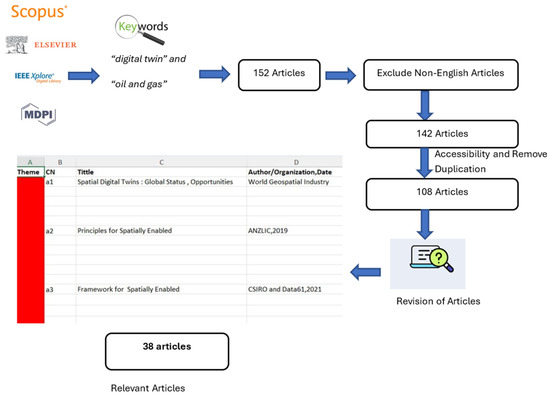
Figure 2.
Literature review approach.
From the literature review, it was found that there is a research gap in linking the digital twin and geospatial domain in the field of the oil and gas industry. The precise definition of the problem, which has already been outlined in the introduction section, was defined. The problem is worth investigating as the 2D-based spatial information system is constrained to visualisation and decision-making. The research problem is significant to the field design stage of a typical oil and gas project. In addition to this, the defined problem is of general interest (digital twin) as various organisations are conducting research and developing activities for effective business decision-making. To find the root cause of the problem, a systematic literature review method (Figure 2) was considered.
3.2. Development Phase
Firstly, the germinal method was used to generate the fundamental concepts for designing the architecture. A “clean sheet of paper” was used for brainstorming to map the field design and spatial information system.
Secondly, after the literature review, it was found that two previous studies explicitly utilised architecture for a spatial DT paradigm [15,17]. The first idea was to integrate these two architectures and customise them in the context of an oil and gas project. The second idea was to develop a new architecture. Therefore, two alternatives were defined: I1: developing new architecture; I2: customising the existing architecture. Johannesson and Perjons [35] discussed various models to assess and select ideas, i.e., the rational decision-making model, bounded rationality, and the garbage model. We used the rational decision-making model as this model is a more effective tool for customising the architecture than developing a new one. Thus, the Microsoft Visio tool was used to create the use case diagram and sequence diagram, as well as the system architecture of the spatially enabled digital twin, which is presented in the results and discussion section.
3.3. Implementation Phase
Firstly, a requirement analysis was carried out. Based on the scope of this study, two main requirements were considered, namely data requirements and prototype requirements. Data are crucial at every step during the field design of any oil and gas project. Throughout the field design of any proposed infrastructure, a wide range of spatial information needs to be considered. Incorporating all the datasets into the system architecture/prototype was difficult within the scope of this study. Therefore, firstly, a literature review was carried out using an LSDM document [43] and existing accessible industry reports [44,45,46]. Secondly, the first author was engaged in a work experience opportunity at a surveying firm (DSQ Land Surveyors, Australia) to ascertain a broader spectrum of data needs aligned with the prevailing methods in the industry setting. Subsequently, six categories of datasets were identified as infrastructure, environment, geology, survey measurements, cultural heritage and safety, which played a crucial role in field design in the context of Australia.
Secondly, the prototype requirement refers to the specific criteria and functionalities that a prototype should exhibit. The main requirement for this prototype was that it should act as physical evidence of the developed system architecture which facilitates the storing of the abovementioned six classes of data in a 2D/3D format and ensures that the prototype successfully displays the stored attributes of the LSDM of the 2D and 3D datasets. Therefore, upon considering the time frame of this study, five major functionalities were considered that include a layer panel, navigation bar, map interface, data upload, and view 2D design plan.
After requirement analysis, a backend system was developed. This involves creating a Django project, configuring the MVC architecture, and defining Django models to represent essential data entities. The PostgreSQL database, augmented with the PostGIS extension for efficient spatial data handling was developed. The Geoserver and Cesium ion were integrated to handle vectors, rasters, and 3D data seamlessly. Simultaneously, frontend development was commenced. The setup of a ReactJS project facilitated the creation of a dynamic and responsive user interface. The React components were utilised to design an intuitive layout. The Resium library was introduced at the frontend of 3D spatial data visualisations, making use of 3D tiles streamed from Cesium ion to enhance the overall user experience. The entire development process was carried out in the Git and Docker environment. Git ensures version control and collaborative development through branching, while Docker containers enable consistent deployment across different environments. Finally, the resulting prototype was hosted on a localhost.
3.4. Demonstration Phase
To demonstrate the viability of the prototype, a real-world study area was first selected. There were two main considerations while selecting the case study area. First, infrastructure should be part of the field design of any typical oil and gas project. Second, a survey (total station/UAV survey/laser scanning/GNSS) was able to be effectively conducted on the proposed study area. Therefore, to validate the developed prototype, this study selected a specific case study site from an oil and gas project, on the lot plan 2RP10845 petroleum lease 229, registered under the State Government of Queensland.
The existing mining-related datasets and geodetic control points information were collected from the Queensland Government GeoResGlobe online platform (https://georesglobe.information.qld.gov.au/, accessed on 26 April 2023) and the GSQ Open Data portal (https://geoscience.data.qld.gov.au/, accessed on 26 April 2023). Pre-flight planning was conducted before conducting the UAV survey. The DJI Phantom 4 Sensor (multi-spectral) was used to acquire 3D point cloud information. The Trimble R10 GNSS receiver was used to densify control points and establish ground control points (GCPs). Proper safety precautions were adopted while conducting the UAV survey near the plant. Agisoft Metashape software v2024 was used for processing the captured UAV images.
In the selected case study area, there were facilities, roads, pipelines, rights-of-way (ROWs), and habitat areas. However, to demonstrate the prototype in the selected case study area, we chose existing two plant facilities (vertical separators and their associated components) located on their respective well pads. This selection was made because these facilities present more complex features compared to others, such as roads, pipelines, rights-of-way (ROWs), and habitat areas. It is obvious that, if the prototype can store and visualise such complex features, we can confidently confirm prototype feasibility in the real-world field design process.
Further, 3D models of the required features such as facilities, roads, well pads, rights-of-way (ROWs), pipelines, and habitat areas were created by integrating as-built data, 3D point cloud data, and auxiliary information. The 3D AutoCAD Plant software v 2024 was used to create a 3D model of the existing facility integrating point clouds, orthophoto, and a digital surface model (DSM). Similarly, other features such as roads, well pads, ROWs, pipelines, and habitat areas were created from UAV-generated orthophoto. The 3D modelling of roads, well pads, ROWs, and pipelines were carried out using the guidelines defined by [47] and the “extrude” tool in Civil 3D software v2024. For the habitat areas, the heights of trees were measured at approximately 4 m in the 3D point cloud and modelling was carried out using the 3D objects available in the Civil 3D software. Then, XML-based scripting was created to accommodate the LSDM attributes of the created 3D models.
3.5. Validation Phase
The prototype was validated using an artificial strategy with the informed argument method as discussed in the design science framework [35]. The performance efficiency of this prototype was evaluated using three key criteria, namely time performance, resource utilisation, and capacity, as defined by [48]. This prototype was compared with the Digital Twin Victoria (DTV) platform, which is an initiative developed by the State Government of Victoria and is capable of displaying 2D, 3D, time dynamic, and real-time data through the web browser [49]. To assess time performance, six 3D features (roads, well pads, ROWs, pipelines, facilities, and habitat areas) were uploaded to both platforms and rendering times were recorded. Further, the stopwatch app available on the Google Pix6a phone was used to record the rendering time. The rendering time was calculated based on how long the DTV and prototype took to render and visualise the 3D plant. Similarly, for resource utilisation and capacity assessment, the prototype was compared with the DTV platform, and comparison results are shown in Section 4.7.
4. Results and Discussion
4.1. System Architecture
The system architecture comprises five primary components: datasets, database management system, map servers, visualisation system, and users, as illustrated in Figure 3. The database management system is one of the major components of the architecture as it stores all the datasets. The database management system stores three key types of datasets: 3D models, 2D vectors, and 2D raster datasets. The various 3D model formats that can be stored in a database management system are .obj, .kml, .kmz, .gltf, .fbx, .citygml, .dae, .las, and .laz. These 3D models can be stored in a database system, which is a distributed file system optimised for streaming and rendering in web-based 3D mapping applications of the Cesium ion. Cesium ion allows the storing of up to 5 GB’s worth of datasets without a subscription [50]. However, to store more than 5 GB, a commercial subscription must be purchased. Similarly, .shp is the commonly used 2D vector data format worldwide. A widely accepted open-source PostgreSQL database with a PostGIS extension is recommended to be used in this system architecture as it can store 2D vector datasets. Further, raster data file formats such as .tif and .geotif can be stored in the file system and published and shared through the GeoServer. This architecture facilitates the storing of LSDM datasets and other datasets available in various file formats. Infrastructure data can be stored in the 3D models. In the architecture, engineering, and construction (AEC) industry, .ifc is the most commonly used file format to represent 3D models of infrastructure designs [33], although Cesium ion does not directly support this format yet.
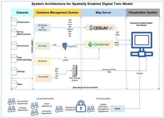
Figure 3.
System architecture.
Consequently, third-party software facilitates the conversion of .ifc files to formats compatible with Cesium ion, as illustrated in Figure 3. Similarly, a 2D vector can be used to store the 2D line works of the infrastructure design. Further, environmental samples, geology, and topo geomorphology can be stored in the 2D vector or raster data format. For 3D representations, file formats such as .kml, .kmz, .gItf, and .obj can also be used.
Capturing ground information through surveying involves varied techniques, resulting in different data formats. UAVs or laser scanners generate 3D point cloud data in .las/.laz file format, while GNSS or total station generates 2D vector points in .shp file format. Similarly, the other real time datasets such as weather and fire associated with the safety class can be streamed through Cesium ion directly.
The map sever is one of the most important parts of the architecture because it acts as the bridge between the visualisation and the database management system. Cesium ion enables the steaming of the 3D tiles of the 3D models stored in its database management system. Similarly, GeoServer supports storing and publishing vector and raster datasets that are stored in the database or file system, enabling web coverage service (WCS), web map service (WMS), and web feature service (WFS). The visualisation system is considered the frontend component of the system architecture. All the 2D, 3D, and 4D datasets that are streamed through map server are rendered on the visualisation platform. The users of this system architecture are primarily stakeholders associated with the field design of typical oil and gas projects. These stakeholders encompass environmentalists, geologists, surveyors, design engineers, and GIS professionals. Similarly, safety officers and cultural heritage officers are also other key stakeholders in the context of Australia. Users can access the system based on their respective roles.
4.2. Use Case Diagram
A use case diagram was developed to visually represent the functional requirements of spatial digital twin architecture. In this study, the primary purposes of creating a use case diagram were to understand system functionality, to design system architecture, and to illustrate the involved users and their responsibilities/associations in the workflow of the field design process. Figure 4 shows the use case diagram of the conceptual system architecture. It depicts the major four sub-systems that encompass conceptual engineering design, detailed engineering design, field surveying, and spatially enabled DT.
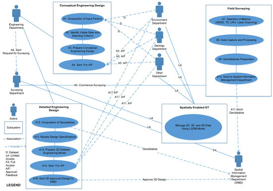
Figure 4.
Use case diagram.
The involved activities are represented using A1, A2,… A16. A1 activity is connected to A2, in which the engineering department begins to acquire various pieces of information from different departments. Then, A3 and A4 activities are conducted by the engineering department team using the results generated from A1 and A2 activities. In A3 and A4, the preliminary designs of the infrastructure are created and sent for approval/feedback. Thus, A5 is an activity related to the status of approval/feedback from every involved department. They have access to the spatially enabled DT where they can acquire the necessary information to make the decision (approved/sent feedback) for the infrastructure design sent from the engineering department. Then, once approvals are obtained from every department, the engineering department sends a request to the surveying department to carry out the A6 activity, i.e., examining the ground conditions.
The surveying department can access the relevant information such as survey control points, and surveying specifications from the spatially enabled DT system which is required to carry out field surveying activities. Then, the surveying department carries out the A7 activity using the designated method, which relies upon the project requirements. They might use GNSS, total station, UAVs, or a laser scanner to collect field data. Further, A8 and A9 are activities related to field data capture and geodatabase creation that are conducted by the surveying department, and the final geodatabase is sent out through the A10 activity to the spatial information management department, whose major role is to ensure that the data are captured correctly and meet project specification.
Once the field surveying is completed and data are correctly stored on the spatially enabled DT, the engineering department again requests that the spatial information management department give them access to the geodatabase to create the detailed engineering designs. Thus, the A12 activity is accomplished, which further allows the A13 activity to analyse how much the design needs to deviate from the conceptual design. Then, activity A14 is carried out by the engineering department to prepare the 3D model of the design. Subsequently, a 3D model is sent to every department for approval/feedback. Upon obtaining approval from each department, the 3D design models are again sent to the spatial information management department to be archived in the spatially enabled DT.
4.3. Sequence Diagram
Figure 5 shows the sequence diagram of the above system architecture for managing spatial information flow and exchange.
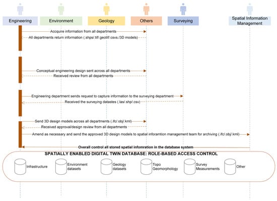
Figure 5.
Sequence diagram.
Firstly, the engineering department acquires all the information from all the departments. Secondly, using that information, the conceptual engineering design of infrastructure is prepared and sent for approval/feedback. Then, based on the feedback received from all the departments, the conceptual engineering design of the infrastructure is finalised. Then, the engineering department sends a request to the surveying department to capture the field data. The surveyor collects the field data and sends it to the engineering department. The engineering department then commences the detailed design of the proposed infrastructure. Subsequently, 3D design models are sent to the respective departments for approval/feedback. Once the approval/feedback is received by the engineering department, it takes appropriate actions on it. Finally, the approved design models of the infrastructure designs are sent to the spatial information management department for archiving.
4.4. Data Requirements in the Field Design and Construction of Oil and Gas Projects
The method used to identify data requirements has already been explained in Section 3.3. Among identified data requirements, as illustrated in Figure 6, infrastructure plays a pivotal role in field design, and other datasets are relevant to the different stages of field design. Subsequently, the environment, geology, cultural heritage, and safety are important sources of information from the relevant disciplines and can impact the design of any infrastructure. Survey measurements are identified as essential for understanding the onsite conditions before proceeding with the detailed engineering design of the proposed infrastructure.
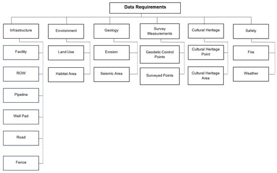
Figure 6.
Data requirements.
4.4.1. Infrastructure
The infrastructure data primarily include the oil and gas company infrastructure assets such as production facilities, ROWs, pipelines, roads, well pads, and fences. Detailed information on the infrastructure category is presented in Table 2.

Table 2.
Infrastructure specifications.
4.4.2. Environment
The environment category consists of a range of datasets related to the environmental aspect. The datasets include information about the edge of vegetation, land use, habitat, flora and fauna, primary protection zone, secondary protection zone, environmental constraint area, and characteristics of water and air. Based on the scope of this research, the identified data are presented in Table 3.

Table 3.
Environmental specifications.
4.4.3. Geology
These datasets support the identification of shallow subsurface features, geological conditions, and any geohazard features that might be hazardous during the construction of the proposed infrastructure. The identified geological datasets with description are presented in Table 4 below.

Table 4.
Geological specifications.
4.4.4. Survey Measurements
These datasets are generally complied before commencing the detailed engineering design. This mainly consists of the geodetic control points as well as onsite surveyed points using various techniques such as total station, GNSS survey, etc. Based on the scope of this research, the considered datasets in this category are presented in Table 5.

Table 5.
Survey specifications.
4.4.5. Cultural Heritage
In the context of Australia, cultural heritage is considered a very important data category because it might impact the overall design of any proposed infrastructure. The cultural heritage datasets with descriptions are presented in Table 6.

Table 6.
Cultural heritage specifications.
4.4.6. Safety
In the context of Australia, safety is considered an important data category because it might impact the overall design of any proposed infrastructure. These are real time or time dynamic datasets. The datasets considered for this category are presented in Table 7.

Table 7.
Safety specifications.
4.5. Implementation of Proposed Architecture: Prototype Development
The developed prototype is illustrated in Figure 7. The prototype encompasses four major components such as layer panel, map interface, navigation bar, and other components. The layer panel serves as a crucial component and is categorised into distinct classes, namely infrastructure, environment, geology, survey measurements, cultural heritage, and safety, as visually represented in the red rectangular box. It provides users with a comprehensive toolset for manipulating and controlling different layers within the prototype. Similarly, the map interface serves as a visual gateway to the 2D, and 3D spatial data encapsulated within the prototype. This essential feature allows users to interact with the spatial data of the infrastructure design and its associated information. The interface provides users with the ability to navigate through the data, seamlessly transitioning between different sections. By offering a user-friendly environment for interaction, this feature enhances the overall accessibility of spatial information, making it easier for users to interpret and derive insights. The map interface is shown in the blue rectangular box. The navigation bar works as a pivotal navigational tool, serving as a gateway to essential functions and features embedded within the prototype. This critical element acts as a centralised hub, providing users with convenient access to different sections and capabilities. The navigation pane is represented in the yellow rectangular box. The other components are represented in the pink box. These components are the default components of the Cesium ion that encompasses the search functionality, view home, 2D and 3D view, and base map layers. The search component facilitates the efficient and user-friendly exploration of geospatial data. Users can input specific locations, addresses, or points of interest, and the system will provide navigation information. The view home feature acts as a quick navigation tool, allowing users to easily return to a predefined default view or home location within the prototype.
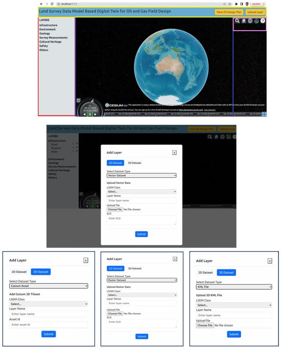
Figure 7.
Prototype.
One of the pivotal components of the prototype is the add layer feature, depicted in Figure 7, which serves as a versatile tool for users to seamlessly include diverse 2D and 3D datasets. A user can upload vector data, specifically in the shapefile (.shp) format. This initial step ensures compatibility and ease of integration with the prototype. Users can select and define LSDM classes for the uploaded layer namely, infrastructure, environment, geology, survey measurements, cultural heritage, and safety, which act as organisational categories for the datasets. Users are required to specify the LSDM class that best corresponds to the nature of their uploaded data. The further refinement of the dataset categorisation involves selecting a specific layer name from the LSDM data category. This classification ensures that datasets are stored in their respective LSDM classes, fostering a systematic and organised data structure within the prototype. To streamline the visualisation and interpretation of the uploaded datasets, users are then prompted to copy the Styled Layer Descriptor (SLD) based on their specific requirements. This step allows users to customise the appearance of the data on the map, tailoring them to meet their analytical or presentation needs.
Notably, the prototype extends its functionality to encompass not only vector datasets but also the storage and management of raster datasets. The process for uploading raster datasets mirrors the user-friendly approach applied to the vector data. Users are guided through a straightforward process, requiring them to select the specific raster datasets that align with their analytical or visualisation needs. Additionally, the prototype efficiently managed 3D spatial datasets through two primary methods, as shown in Figure 7. The first approach involved the storage of data via separated Keyhole Markup Language (KML) files, following a process that corresponds to that employed for vector datasets. Conversely, the second method centred around utilising Cesium ion asset IDs for 3D vector data storage. Users are required to input the specific asset id associated with the desired data, a process that involves referencing the Cesium ion database.
4.6. Prototype Demonstration: A Case Study
Figure 8 illustrates the chosen case study area along with its elevation range. It is located in Queensland, Australia, within the Dalby mining district and situated within the Western Downs Regional Council. This case study area is situated at lot number 2RP108045, petroleum lease 229, registered under the Department of Resources, Queensland Government.
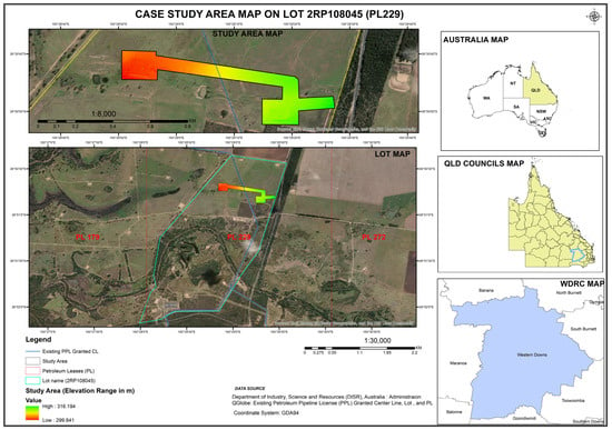
Figure 8.
Study area.
4.6.1. UAV Survey Results and 3D Models
The key results derived from UAV data processing encompass 3D models, orthophotos, and digital surface models (DSMs), as depicted in Figure 9. The 3D models were exported in the .las and .obj file formats, while the orthophotos and DSMs were exported in the .tif file format. The spatial resolutions of the obtained orthophotos and DSMs were determined to be 1.5 cm and 2.6 cm, respectively. The calculated errors in Easting (X), Northing (Y), and Elevation (Z) were found to be 2.814 mm, 3.520 mm, and 3.940 mm, respectively. These individual errors cumulatively contribute to a total error of 5.989 mm.
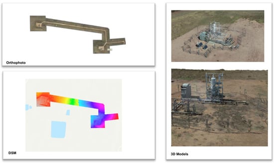
Figure 9.
UAV results.
Similarly, Figure 10A shows the developed 3D model of the facilities in the AutoCAD Plant. The presented 3D model consists of fences, vertical separator, valves, and other as-built information which falls under the “infrastructure” LSDM class. Similarly, Figure 10B shows the other datasets, which fall under the “infrastructure” and “environment” LSDM classes. For instance, ROWs, roads, and pipelines fall under the “infrastructure” class, whereas “habitat areas” falls under the “environment” class. The 3D models represented in Figure 10 are georeferenced models.
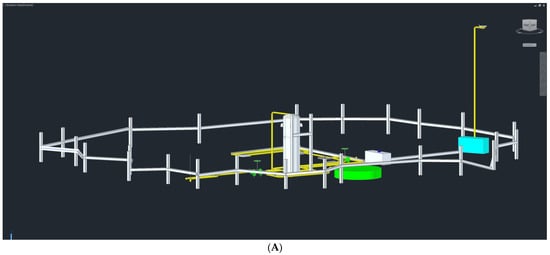
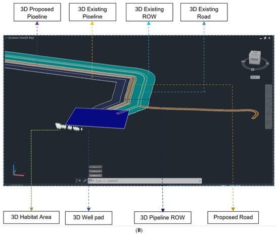
Figure 10.
Three-dimensional models (A). Three-dimensional models (B).
Accommodating LSDM-based attributes and visualising the 3D infrastructure designs was one of the major tasks in this study. Autodesk Navisworks software v2024 was used to convert the .dwg file to a 3D KML file, and the XML script was used to integrate the defined attributes. An example of the XML script used to integrate the LSDM attributes to the 3D model is shown in Figure 11.
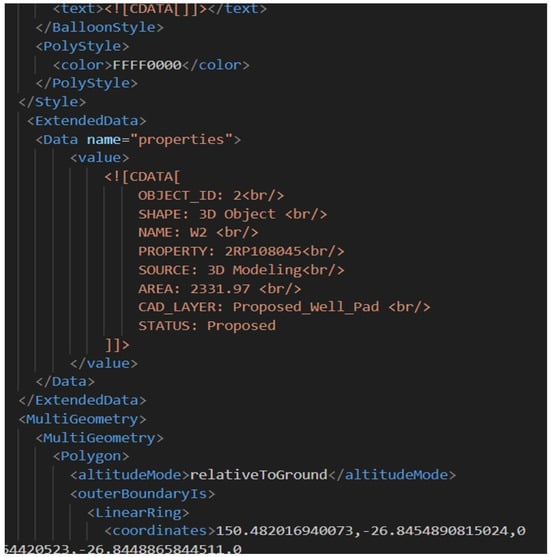
Figure 11.
XML script.
4.6.2. Uploading 3D Model into the Prototype
Only the prepared 3D model (facilities) is shown. It had a .kml file format and was uploaded with the KML data type using the data uploading function of the prototype. The outputs are depicted in Figure 12. The facilities were successfully visualised and their relevant LSDM attributes were successfully displayed on the prototype, as illustrated in Figure 12.
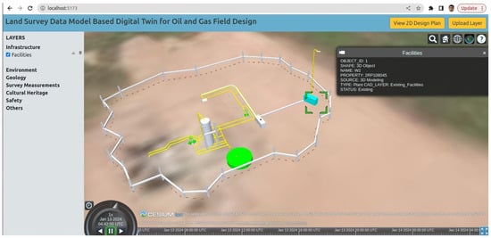
Figure 12.
Uploaded model to prototype.
4.7. Prototype Validation
As we discussed in Section 3.5, the performance efficiency was evaluated using three criteria, i.e., time performance, resource utilisation, and capacity. The prototype was compared with the Digital Twin Victoria platform. Figure 13 illustrated the rendering time comparison of the six features (3D models). The most complex 3D object was facilities, and it took 10.7 s to render in the prototype whereas the DTV platform took 13.3 s. This approximately 3 s discrepancy may be attributed to the vast amount of data (4000 plus) within the DTV platform. Similarly, other smaller 3D objects, such as roads, well pads, ROWs, and pipelines, showed similar rendering time. Therefore, it can be stated that the developed prototype is capable of rendering 3D objects within a reasonable timeframe. Some of the complex 3D data (facilities) were successfully uploaded to the DTV, as shown in Figure 14.
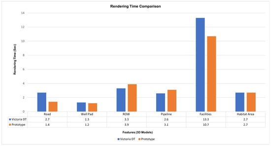
Figure 13.
Rendering time comparison.
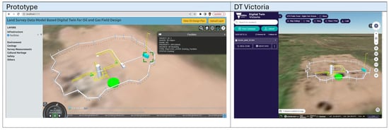
Figure 14.
Facilities in the prototype and the DTV.
The resources (libraries) utilised in the prototype were free and open-source libraries, such as Geoserver, Cesium ion (free subscription), and PostgreSQL, used to visualise and populate the LSDM attributes. Similarly, the DTV core components were also built using free and open-source libraries. In terms of capacity, the prototype was able to visualise the 3D objects and associated spatial information based on LSDM attributes for specific O&G projects. However, the DTV platform is a dynamic 3D digital representation of Victoria’s built and natural environment and is capable of displaying a digital model of Victoria by combining trillions of data points.
Currently, the prototype has a maximum of 5 GB storage to hold the datasets through the free subscription to Cesium ion. DTV manages various themes of data in the context of the built and natural environments, ranging from cadastre, land administration, transportation, railways, etc., as illustrated in Figure 15. The reason for this is that DTV is based on Cesium ion (commercial license). The prototype has the unique functionality of being able to download the uploaded 3D object, which is not possible in DTV, as illustrated in Figure 15.
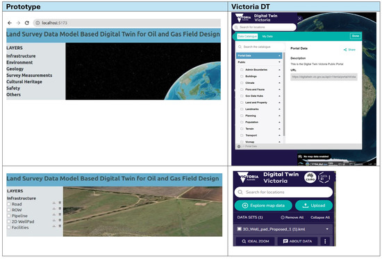
Figure 15.
Capacity of the prototype.
The prototype was successfully tested and was able to visualise 3D spatial data and associated LSDM attribute information. The prototype performed well in terms of rendering time, resource utilisation, and capacity, which indicated its success within the defined study scope.
4.8. Discussion
With the emergence of cutting-edge digital technology, specifically spatial digital twins, every industry is considering its adoption due to its capability to depict spatial information precisely and efficiently. To effectively manage spatial information on digital twin platforms, the system architecture is crucial. There are several existing studies that have highlighted the system architectures of digital twins. In general, these studies have developed and tested system architecture associated with digital twins focused on urban land infrastructure, oil and gas manufacturing, and utility infrastructure. Therefore, our study made the effort to develop system architecture for spatially enabled digital twins that explicitly focuses on spatial information management for the field design of the oil and gas industry and was implemented by developing a prototype and validating it in a case study area. A spatially enabled digital twin is considered a powerful tool for addressing the challenges caused by 2D plans in the oil and gas field design process. This study proposes five components of spatially enabled digital twin architecture and implements them through a real-world case study. Table 8 summarises the description of each component of the developed architecture based on spatially enabled digital twin platforms. Additionally, Table 8 illustrates the components of the system architecture in the context of field design for a typical oil and gas project. Therefore, this architecture can be deployed in oil and gas projects as it addresses the challenges induced by traditional 2D systems.

Table 8.
Summary of components of the architecture.
The developed architecture and the prototype in this study represent a novel idea for managing spatial information in the context of field design within the oil and gas industry. Concepts, tools, and techniques used in architecture were customised from existing studies because they cannot be directly implemented in the oil and gas industry due to the absence of LSDM constituents. The fundamental concept of this architecture relies on the generic architecture developed by Rajafibard et al. [15]. This study introduced a new digital twin model that had not been investigated previously, focusing on the LSDM model. Therefore, the developed architecture and prototype could serve as a starting point to leverage digital twins for managing spatial information in the context of field design in the oil and gas industry.
5. Conclusions and Future Work
The concept of a spatially enabled digital twin is evolving as a powerful tool across various sectors that rely on spatial information. Industries such as infrastructure, utilities, construction, asset and facilities management, and mining are increasingly leveraging this technology to enhance visualisation, improve analytics, and enable socio-economic applications. The oil and gas sector are also considering digital twin technologies for numerous applications including asset monitoring, drilling, virtual commissioning, and the development of intelligent oilfields.
This research study followed the design science research approach and adopted five major phases, namely the foundation phase, the development phase, the implementation phase, the demonstration phase, and the validation phase, as suggested by Johannesson and Perjons [35], for developing spatial digital twin architecture for the field design process of oil and gas projects in Australia. This study developed conceptual digital twin architecture comprising five key components, i.e., data classes, a database management system, map server, a visualisation system, and users. In this study, it was shown that existing DT architecture lacks the incorporation of industry-standard data models, such as LSDM. This study developed a spatially enabled DT architecture, integrating LSDM, allowing the storage and visualisation of the spatial data of infrastructure design within a 3D environment of oil and gas projects. Additionally, this study provides insights into the relationship between the developed architecture and the field design process using use case diagrams and sequence diagrams. The use case diagrams encompass the 16 activities that commence from the acquisition of input factors to the uploading of the 3D models into the spatially enabled digital twin. Furthermore, sequence diagrams illustrate the steps of the flow of spatial information across various departments of field design. This study also identified six major categories of data that play a pivotal role in the field design process. The datasets include infrastructure, environment, geology, survey measurements, cultural heritage, and safety. To assess the viability of the system architecture, a prototype was developed and successfully demonstrated through a case study. The prototype encompasses four major components, namely the layer panel, the map interface, the navigation bar, and other components. In addition to this, the prototype was successfully able to visualise the 2D and 3D spatial data and associated LSDM attribute information. Moreover, the prototype performance efficiency was evaluated by comparing it with working application, i.e., Digital Twin Victoria (DTV) platform, which signified that the prototype performed well in terms of rendering time, resource utilisation, and capacity. However, it is worth mentioning that there were many challenges in the creation of a compatible environment.
This study significantly contributed to four areas. Firstly, this study outlined a spatially enabled digital twin architecture and implemented it in the real word in a field design context, which is rarely found in the existing academic literature, offering a valuable resource for researcher and practitioners. Secondly, this study provides knowledge to all the relevant stakeholders and practitioners for leveraging emerging digital twin technology in the geospatial domain of the O&G industry context. Stakeholders include surveying and mapping companies, surveyors, asset engineers/managers, and field construction crews dealing with the geospatial sector of the O&G industry. Thirdly, this research utilised a design science research approach, which provides a theoretical contribution to the information science domain within the O&G industry. Finally, from a high-level perspective, this study contributes to the advancement of Industrial Revolution 4.0 within the mining industry and facilitates better decision-making in the oil and gas industry sector.
The scope of this research study was to develop a system architecture for spatially enabled digital twins during the field design phase of oil and gas projects and implement it in the real-world case study area using a design science approach. However, there are some limitations in this study. It is recommended that further research should be conducted for the validation of the developed prototype through focus group discussion with stakeholders and/or using the parameters stated by ISO/IEC 25010 [51]. As the selected case study area was Queensland, Australia, it limits the generalisability of the findings to other geographical regions that have different regulatory frameworks and/or infrastructure characteristics. Additionally, the system architecture is designed based on the data requirements of the LSDM model, and additional data can be incorporated into the architecture as needed for specific oil and gas projects.
Author Contributions
Conceptualization, S.B., D.R.P. and S.C.; methodology, S.B., D.R.P. and S.C.; software, S.B., investigation, S.B.; data collection, processing, analysis, visualisation, S.B., D.R.P. and S.C. writing—original draft preparation, S.B.; writing—review and editing, D.R.P.; supervision, D.R.P. and S.C.; project administration, D.R.P. and S.C. All authors have read and agreed to the published version of the manuscript.
Funding
This research received no external funding. This research was supported by the Graduate Research School, University of Southern Queensland (UniSQ), and is part of the first author’s HDR project entitled “Developing spatially enabled digital twin framework for field design process of oil and gas projects”.
Data Availability Statement
The data supporting the findings of this study are available from the first author upon reasonable request. The data are not publicly available due to privacy restrictions.
Conflicts of Interest
The authors declare no conflicts of interest.
References
- Abdul Rahim, A.; Sabri, H.A.R.; Yew, W.; Ismail, S. Project Management in Oil and Gas Industry: A Review. In Proceedings of the 26th International Business Information Management Association (IBIMA) Conference, Madrid, Spain, 11–12 November 2015. [Google Scholar]
- International Association of Oil and Gas Producers (IOGP). Environmental Management in the Upstream Oil and Gas Industry; IOGP: London, UK, 2020. [Google Scholar]
- Shell QGC. Constraints Planning and Field Development Protocol QGC Upstream Project; Shell QGC: Brisbane City, QLD, Australia, 2017. [Google Scholar]
- Deogawanka, S. GIS in Oil and Gas. Available online: https://www.gislounge.com/gis-in-oil-and-gas/ (accessed on 15 April 2024).
- Young, A.; Rogers, P. A Review of Digital Transformation in Mining. Min. Metall. Explor. 2019, 36, 683–699. [Google Scholar]
- Minerals Council of Australia. The Digital Mine. Available online: https://minerals.org.au/wp-content/uploads/2022/12/The-Digital-Mine_2022.pdf (accessed on 25 April 2024).
- Sinha, S.; Walton, G. Application of an Integrated 3D–2D Modeling Approach for Pillar Support Design in a Western US Underground Coal Mine. Geosciences 2023, 13, 333. [Google Scholar] [CrossRef]
- Santos, E.T. Building Design Coordination: Comparing 2D and 3D Methods. In Proceedings of the CIB W78 2008 International Conference on Information Technology in Construction, Santiago, Chile, 15–17 July 2008. [Google Scholar]
- Sharafat, A.; Khan, M.S.; Latif, K.; Tanoli, W.A.; Park, W.; Seo, J. BIM-GIS-Based Integrated Framework for Underground Utility Management System for Earthwork Operations. Appl. Sci. 2021, 11, 5721. [Google Scholar] [CrossRef]
- Eldeep, A.M.; Farag, M.A.M.; Abd El-hafez, L.M. Using BIM as a Lean Management Tool in Construction Processes—A Case Study. Ain Shams Eng. J. 2022, 13, 101556. [Google Scholar] [CrossRef]
- Wong, J.; Zhou, X.; Chan, A. Exploring the Linkages Between the Adoption of BIM and Design Error Reduction. Int. J. Sustain. Dev. Plan. 2018, 13, 108–120. [Google Scholar] [CrossRef]
- Zhu, J. Integration of Building Information Modelling and Geographic Information System at Data Level Using Semantics and Geometry Conversion Approach towards Smart Infrastructure Management. Ph.D. Thesis, Curtin University, Perth, WA, Australia, 2018. [Google Scholar]
- World Geospatial Industry Council (WGIC). Spatial Digital Twins: Global Status, Opportunities, and the Way Forward. 2022. Available online: https://wgicouncil.org/world-geospatial-industry-council-releases-a-report-on-spatial-digital-twins-trends-and-opportunities/ (accessed on 13 April 2024).
- Wanasinghe, T.R.; Wroblewski, L.; Petersen, B.K.; Gosine, R.G.; James, L.A.; Silva, O.D.; Mann, G.K.I.; Warrian, P.J. Digital Twin for the Oil and Gas Industry: Overview, Research Trends, Opportunities, and Challenges. IEEE Access 2020, 8, 104175–104197. [Google Scholar] [CrossRef]
- Abbas Rajabifard, S.S.; Chen, Y. Digital Twin for the Next Generation of Urban Land Administration and 3D Spatial Planning. In Proceedings of the FIG Congress 2022: Volunteering for the Future—Geospatial Excellence for a Better Living, Warsaw, Poland, 11–15 September 2022. [Google Scholar]
- ESRI. ArcGIS: The Foundation for Digital Twins; An Infrastructure ebook; ESRI: Redlands, CA, USA, 2022. [Google Scholar]
- Aleksandrov, M.; Diakité, A.; Yan, J.; Li, W.; Zlatanova, S. Systems Architecture for Management of BIM, 3D GID and Sensors Data. ISPRS Ann. Photogramm. Remote Sens. Spat. Inf. Sci. 2019, IV-4/W9, 3–10. [Google Scholar] [CrossRef]
- International Association of Oil and Gas Producers (IOGP). LSDM Model; IOGP: London, UK, 2022. [Google Scholar]
- Laurini, R.; Thompson, D. Fundamentals of Spatial Information Systems; Academic Press: Cambridge, MA, USA, 1998; Volume 37. [Google Scholar]
- El-Reedy, M.A. Chapter 1—Engineering Management. In Onshore Structural Design Calculations; El-Reedy, M.A., Ed.; Butterworth-Heinemann: Oxford, UK, 2017; pp. 1–12. [Google Scholar]
- Sustainable Built Environment National Research Centre. National BIM Guidelines and Case Studies for Infrastructure: SBENRC Project 3.28 2017; Sustainable Built Environment National Research Centre: Perth, WA, Australia, 2017. [Google Scholar]
- Mokhatab, S.; Mak, J.Y.; Valappil, J.V.; Wood, D.A. Chapter 11—LNG Project Management. In Handbook of Liquefied Natural Gas; Gulf Professional Publishing: Boston, MA, USA, 2014; pp. 465–498. [Google Scholar]
- Grieves, M. Digital Twin: Manufacturing Excellence through Virtual Factory Replication. White Pap. 2015, 1, 1–7. [Google Scholar]
- Defense Acquisition University. Glossary of Defense Acquisition Acronyms & Terms; Defense Acquisition University: Belvoir, VI, USA, 2015. [Google Scholar]
- Parrott, A.; Warshaw, L. Industry 4.0 and the Digital Twin. Available online: https://www2.deloitte.com/us/en/insights/focus/industry-4-0/digital-twin-technology-smart-factory.html (accessed on 25 April 2024).
- Zhang, T.; Sun, S. An Exploratory Multi-scale Framework to Reservoir Digital Twin. Adv. Geo-Energy Res. 2021, 5, 239–251. [Google Scholar] [CrossRef]
- Shen, F.; Ren, S.S.; Zhang, X.Y.; Luo, H.W.; Feng, C.M. A Digital Twin-Based Approach for Optimisation and Prediction of Oil and Gas Production. Math. Probl. Eng. 2021, 2021, 3062841. [Google Scholar] [CrossRef]
- Bevilacqua, M.; Bottani, E.; Ciarapica, F.E.; Costantino, F.; Di Donato, L.; Ferraro, A.; Mazzuto, G.; Monteriù, A.; Nardini, G.; Ortenzi, M.; et al. Digital Twin Reference Model Development to Prevent Operators Risk in Process Plants. Sustainability 2020, 12, 1088. [Google Scholar] [CrossRef]
- Xue, X.; Li, B.; Gai, J. Asset Management of Oil and Gas Pipeline System Based on Digital Twin. IFAC Pap. 2020, 53, 715–719. [Google Scholar]
- Lv, Z.; Lv, H.; Fridenfalk, M. Digital Twins in the Marine Industry. Electronics 2023, 12, 2025. [Google Scholar] [CrossRef]
- Konchenko, A.; Chatar, C.; Doronichev, S.; Saetern, D.; Bruns, J. Oilfield Virtual Twin. In Proceedings of the SPE Annual Technical Conference and Exhibition, Online, 26–29 October 2020. [Google Scholar]
- Lu, Q.; Parlikad Ajith, K.; Woodall, P.; Don Ranasinghe, G.; Xie, X.; Liang, Z.; Konstantinou, E.; Heaton, J.; Schooling, J. Developing a Digital Twin at Building and City Levels: Case Study of West Cambridge Campus. J. Manag. Eng. 2020, 36, 05020004. [Google Scholar] [CrossRef]
- Chen, Y.; Shooraj, E.; Rajabifard, A.; Sabri, S. From IFC to 3D Tiles: An Integrated Open-Source Solution for Visualising BIMs on Cesium. ISPRS Int. J. Geo-Inf. 2018, 7, 393. [Google Scholar] [CrossRef]
- Lee, J.; Lee, Y.; Hong, C. Development of Geospatial Data Acquisition, Modeling, and Service Technology for Digital Twin Implementation of Underground Utility Tunnel. Appl. Sci. 2023, 13, 4343. [Google Scholar] [CrossRef]
- Johannesson, P.; Perjons, E. An Introduction to Design Science; Springer: Berlin/Heidelberg, Germany, 2021. [Google Scholar]
- Al Turki, A.; Gable, G.; Bandara, W. The Design Science Research Roadmap: In Progress Evaluation. In Proceedings of the 17th Pacific Asia Conference on Information Systems (PACIS), Jeju Island, Republic of Korea, 18–22 June 2013; pp. 1–15. [Google Scholar]
- Blessing, L.; Chakrabarti, A. DRM, A Design Research Methodology; Springer: Berlin/Heidelberg, Germany, 2009. [Google Scholar]
- Çağdaş, V.; Stubkjær, E. Design Research for Cadastral Systems. Comput. Environ. Urban Syst. 2011, 35, 77–87. [Google Scholar] [CrossRef]
- Kehily, D.; Underwood, J. Design Science: Choosing an Appropriate Methodology for Research in BIM. In Proceedings of the CITA BIM Gathering 2015, Dublin, Ireland, 12–13 November 2015. [Google Scholar]
- Kuechler, B.; Vaishnavi, V. On Theory Development in Design Science Research: Anatomy of a Research Project. Eur. J. Inf. Syst. 2008, 17, 489–504. [Google Scholar] [CrossRef]
- Muntaheen, A.S.M. The Introduction of the Water Fall Model. Am. J. Comput. Sci. Eng. 2021, 9, e010. [Google Scholar]
- Kitchenham, B.; Brereton, P. A Systematic Review of Systematic Review Process Research in Software Engineering. Inf. Softw. Technol. 2013, 55, 2049–2075. [Google Scholar] [CrossRef]
- International Association of Oil and Gas Producers. Guidelines For Delivery and Use of the Land Survey Data Model. 2022. Available online: https://www.iogp.org/workstreams/engineering/geomatics/land-survey-data-model/ (accessed on 4 June 2024).
- Viva Energy. Pipeline Consultation Plan: Proposed Gas Terminal Pipeline. 2020. Available online: https://www.vivaenergy.com.au/ArticleDocuments/1040/Pipeline%20Consultation%20Plan%20Rev%200%20compiled.pdf.aspx (accessed on 4 June 2024).
- Senex Energy. Western Surat Gas Project. 2022. Available online: https://senexenergy.com.au/wp-content/uploads/2023/10/WSGP-EPBC-Report-2022.pdf (accessed on 4 June 2024).
- Queensland Government. Santos GLNG Gas Field Development Project. 2015. Available online: https://www.statedevelopment.qld.gov.au/coordinator-general/assessments-and-approvals/coordinated-projects/completed-projects/santos-glng-gas-field-development-project (accessed on 4 June 2024).
- AS 2885.0-2008; Pipelines—As and Liquid Petroleum. Standards Australia: Sydney, NSW, Australia, 1997.
- Keibach, E.; Shayesteh, H. BIM for Landscape Design Improving Climate Adaptation Planning: The Evaluation of Software Tools Based on the ISO 25010 Standard. Appl. Sci. 2022, 12, 739. [Google Scholar] [CrossRef]
- Victoria Government. Digital Twin Victoria. 2024. Available online: https://digitaltwin.vic.gov.au/public/ (accessed on 1 June 2024).
- Cesium. Cesium Ion Pricing Plans. 2023. Available online: https://cesium.com/platform/cesium-ion/pricing/ (accessed on 1 June 2024).
- ISO/IEC 25010-2023; Software and Data Quality, International Standard Organisation. ISO: Geneva, Switzerland, 2023. Available online: https://iso25000.com/index.php/en/iso-25000-standards/iso-25010 (accessed on 17 June 2024).
Disclaimer/Publisher’s Note: The statements, opinions and data contained in all publications are solely those of the individual author(s) and contributor(s) and not of MDPI and/or the editor(s). MDPI and/or the editor(s) disclaim responsibility for any injury to people or property resulting from any ideas, methods, instructions or products referred to in the content. |
© 2024 by the authors. Licensee MDPI, Basel, Switzerland. This article is an open access article distributed under the terms and conditions of the Creative Commons Attribution (CC BY) license (https://creativecommons.org/licenses/by/4.0/).