Article

Assessing Air Pocket Pressure Pulses in Sealed Manholes of Urban Drainage Systems Under Pressurisation Conditions

by
Oscar E. Coronado-Hernández
1,*,
Javier A. Mouthón-Bello
1,
Alfonso Arrieta-Pastrana
1,
Modesto Pérez-Sánchez
2 and
Helena M. Ramos
3,*
1
Instituto de Hidráulica y Saneamiento Ambiental, Universidad de Cartagena, Cartagena 130001, Colombia
2
Departamento de Ingeniería Hidráulica y Medio Ambiente, Universitat Politècnica de València, 46022 Valencia, Spain
3
Civil Engineering, Architecture and Environment Department, CERIS, Instituto Superior Técnico, University of Lisbon, 1049-001 Lisbon, Portugal
*
Authors to whom correspondence should be addressed.
Water 2025, 17(7), 984; https://doi.org/10.3390/w17070984
Submission received: 11 February 2025 / Revised: 22 March 2025 / Accepted: 25 March 2025 / Published: 27 March 2025
(This article belongs to the Special Issue Urban Water Management: Challenges and Prospects)

Abstract

:
An entrapped air pocket can induce pressure surges in sewer systems. Previous studies on entrapped air in these systems have focused on analysing its effects under conditions where air is expelled. This research introduces a mathematical model to calculate pressure surges caused by air pocket compression in a sealed manhole (without an orifice size) that may occur at the output of a pumping station. The model is based on the rigid water column theory, the polytropic law, and the continuity equation. The proposed model is validated using a 7.3 m long experimental facility equipped with a sealed chamber simulating a sealed manhole cover. It is demonstrated to accurately predict the peak pressure head of 18.9 metres and the associated pressure oscillations. A sensitivity analysis is also performed to assess variations in model behaviour. Furthermore, the model effectively captures the system’s final conditions. Lastly, a case study illustrates the model’s applicability to a water installation with a length of 250 m.

1. Introduction

Urban drainage systems must operate under free-surface flow conditions, where specific hydraulic parameters should be carefully controlled [1]. These include limiting tractive force, maintaining maximum and minimum water velocities, ensuring proper flow depth-to-rise ratios, and adhering to the minimum internal conduit diameters stipulated by local regulations. Sewer systems mainly characterise themselves by relatively consistent hourly flows.
The Saint Venant equations [2] are commonly applied in most commercial software to analyse variations in hydraulic grade lines for the free-surface zone [3,4,5]. This theory assumes that pipes remain in continuous contact with the atmosphere and that manholes either expel or admit sufficient air to prevent compression or expansion of the air phase within the system [6]. When sewer systems are analysed, then the gradually varied flow theory can be applied for analysing the hydraulic grade line [4].
However, certain hydraulic elements, such as inverted siphons and pumping stations, may need to operate under pressure to ensure a functional and practical design. The transition from a pressurised system to free-surface flow is managed through manholes, which serve as critical interfaces between the two flow regimes [7,8].
Manholes are generally equipped with removable covers to facilitate maintenance [9], particularly for removing solids that accumulate within sewer systems. These removable covers provide convenient access, ensure the system’s long-term functionality, and enable compliance with operational standards.
In many situations, urban drainage systems become surcharged when the water flow exceeds the capacity of the conduits, leading to the pressurisation of both conduits and manholes [10,11].
Reference [12] investigates the behaviour of stormwater storage tunnels under pressurisation conditions, drawing a comparison with an experimental facility featuring a 14.6 m long pipeline with a diameter of 94 mm. That study focuses on the processes occurring during tunnel filling. Subsequently, a two-component pressure model was developed to analyse the transition between free-surface flow and pressurised conditions during the filling processes in urban drainage systems [13]. The analysis has been expanded to consider circular pipes and other shapes [14].
The phenomenon of geysering in stormwater storage tunnels and vertical rise-chamber installations has been explored [15,16]. This phenomenon is characterised by the movement of an air pocket capable of displacing a portion of the water column to the surface, resulting in flooding and creating hazardous conditions in urban areas. The research employed a 4.15 m long pipeline with a 94 mm diameter and a ventilation tower measuring 0.61 m. Experimental investigations were conducted in an upstream vertical shaft to better understand this hydraulic event, which is primarily caused by operational challenges [17,18].
The assessment of maximum air pressure within manholes can be conducted using the elastic and rigid water column theories, akin to the methodologies employed in water distribution networks during filling operations [19,20,21]. In such scenarios, the air phase is typically confined within pipe branches. However, in urban drainage systems, the air phase must be analysed within the barrel and cone sections of manholes. In practice, the application of both elastic and rigid water column theories yields similar results in simulating air pocket pressure pulses in water systems with entrapped air [22], as the elasticity of the air is significantly greater than that of the barrel and cone sections of a manhole.
In recent years, increasing attention has been given to the displacement of manhole covers caused by air pocket compression within the barrel and cone manholes [23]. This scenario features a ventilation orifice that expels the entrapped air by reducing absolute air pocket pressure. This effect can be compared to the compression of air pockets using air valves during filling operations in water distribution systems [19,24,25]. The entrapped air within the barrel and cone sections does not undergo compression as it remains in contact with the atmosphere. However, if the water flow increases, flooding may occur, leading to urban contamination [26].
To mitigate this issue, manhole covers can be completely sealed, creating an unventilated situation where air can neither be admitted to nor expelled from urban drainage systems. While this solution effectively prevents contamination, it also compresses the air phase. The compression of the air phase generates air pocket pressure that must be carefully analysed from a structural perspective to prevent the potential collapse of the manhole.
The existing literature reveals various analyses of manhole covers with an orifice. Martin (1976) [27] introduced the first formulations related to water pipelines with expelled air at the downstream end. Subsequently, Reference [28] examined various conditions in sewer systems, including the analysis of rapid filling in pipes while considering the effects in a horizontal branch, a vertical pipe branch, and a T-pipe branch, all of which contained an orifice for expelling entrapped air. A similar analysis was conducted in Reference [29] using an experimental facility with a ventilation shaft. Wang and Vasconcelos [30] developed a Computational Fluid Dynamics model to investigate the behaviour of a manhole cover, taking into account a shaft diameter and an orifice for air expulsion. Analyses of transient events in cases where the orifice area is zero have been extensively carried out for entrapped air within pressurised water pipelines [20,21,27]. However, there is a lack of studies on air pockets located in sealed manholes, a situation that may occur at the outlet of pumping stations in sewer systems.
This research proposes a mathematical model to compute air pocket oscillations in sealed manholes. These oscillations arise due to surcharge conditions in sewer systems where manhole covers have been sealed to prevent urban flooding. This study examines sewer systems operating under pressurised conditions, particularly at the outlet of a pumping station. Large air pockets become trapped within a sealed manhole. The proposed model does not account for the transition from free-surface to pressurised flow.
The proposed model considers the rigid water column theory for the water phase, the polytropic law for the air phase in a manhole, and the continuity equation applied to a scenario where there is no expelled air (without an orifice). This research introduces a novel approach compared to previous studies, which have primarily focused on scenarios involving expelled air (with an orifice). Furthermore, the proposed model employs the continuity equation in a manhole to describe a physical situation that must be accurately modelled for engineers and designers to determine the maximum pressure that can be reached. In this scenario, elastic and rigid water column models tend to yield similar results, as air elasticity is significantly greater than that of water and the manhole structure.
The proposed model was applied to a practical case study to demonstrate its utility, highlighting significant pressure surges that may occur in pumping stations of sewer systems. Furthermore, the model was validated using a 7.3 m experimental facility configured to replicate the conditions of the practical application.

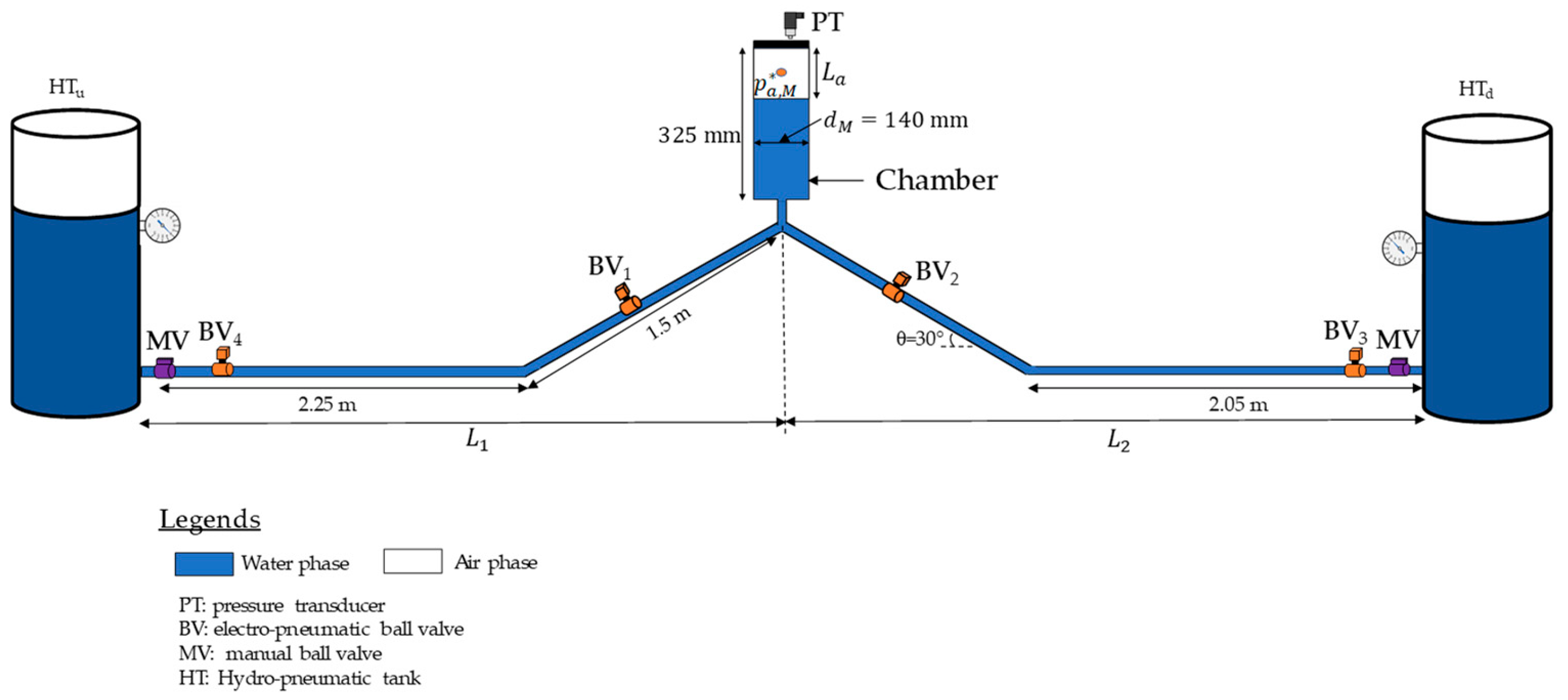
2. Materials and Methods

This section outlines the methodology developed in this research to explore air pocket pressure pulses in non-ventilated manholes (sealed manhole covers), which prevent air exchange with the surrounding environment within this part of the urban drainage system. Such a scenario can lead to the compression of entrapped air pockets in the manhole if the hydraulic installation is subjected to pressurisation. Figure 1a illustrates a schematic representation (profile view) of this situation involving an intermediate sealed manhole cover. In this case, a pumping station is located at the upstream end. A constant water level is present at the downstream end.
The current hydraulic analysis does not consider the scenario for analysing the hydraulic grade line explored in this research (sealed manhole cover), where the air pocket pressure in the sealed manhole ( p a , M * ) changes over time due to the compression of the air phase. The subscript 0 refers to an initial condition. In this condition, the air pocket size and the air pocket pressure are identified as L a , 0 and p a , M , 0 * , respectively, as shown in Figure 1b,c. Figure 1c shows the values of the air pocket size and pressure for an intermediate condition.

2.1. Assumptions

The development of the proposed simulation methodology was based on the following assumptions:
  • The water phase is modelled using the rigid water column theory since the elasticity of the air phase (occurring inside a manhole) is much higher than the water’s elasticity and the volumetric changes of the wall of a manhole.
  • The air phase is simulated by employing the polytropic law.
  • The manhole cover is completely sealed.
  • The continuity equation is applied to the sealed manhole cover.

2.2. Governing Equations

Based on the assumptions above, the proposed model is yielded by the following equations:
a.
The mass oscillation equation between the upstream end and the manhole (sealed cover):
d V u d t = h u + 10.33 γ w p a , M * ρ w L u + z u z M g L u f V u V u 2 D u K t V d V d 2 L u g R v , 1 V u V u A u 2 L u
where V u = the water velocity of a conduit located at the upstream end of a sealed manhole cover, h u = upstream water level, γ w = water unit weight, ρ w = water density, p a , M * = the air pocket’s absolute pressure in the sealed manhole cover, L u = the length of the conduit located at the upstream end of the sealed manhole cover, z u = the invert elevation of a manhole located at the upstream end of the sealed manhole cover, z M = the invert elevation of the sealed manhole cover, g = gravitational acceleration, f = the friction factor of a pressurised conduit, D u = the internal pipe diameter of the upstream conduit, K t = the manhole energy losses coefficient, R v , 1 = the resistance coefficient of the regulating valve located after a pumping station, and V d = the water velocity of a conduit located at the downstream end of the sealed manhole cover.
b.
The mass oscillation equation between the manhole and the downstream end:
d V d d t = p a , M * h d + 10.33 γ w ρ w L d + z M z d g L d f V d V d 2 D d g R v , 2 V d V d A d 2 L d
where h d = the water level at the outfall, L d = the conduit length located at the downstream end of the sealed manhole cover, z d = the invert elevation of a manhole located at the downstream end of the sealed manhole cover, R v , 2 = the resistance coefficient of valves (e.g., duckbill valves), and A d = the cross-sectional area of a conduit located at the downstream end of the sealed manhole cover.
c.
The polytropic equation applied to the manhole:
p a , M * L a k = p a , 0 , M * L a , 0 k = constant
where k = the polytropic coefficient and L a = air pocket length. The subscript 0 refers to the initial condition.
The polytropic coefficient must be calibrated during the experimental stages. However, this coefficient can vary depending on the system’s characteristics in real sewer systems, ranging from 1.0 (isothermal evolution) to 1.4 (adiabatic evolution). An intermediate evolution (with a value of 1.2) can be used for practical applications.
d.
The continuity equation applied to the manhole:
d w , M d t = V u A u V d A d
where w , M = the water volume inside of the sealed manhole cover.
w , M = T , M a , M = T , M π d M 2 4 L a
where T , M = the total volume of a manhole, a , M = air volume, and d M = manhole diameter.
d w d t = π d M 2 4 d L a d t
d L a d t = 4 V u A u V d A d π d M 2

2.3. Boundary and Initial Conditions

The issue of entrapped air in the sealed manhole cover is caused by a pumping station that imposes the boundary condition at the upstream end, and at the other end, the water level in the downstream manhole yields to it.
The initial conditions causing this problem are the following: (i) the air pocket pressure, which is usually characterised by atmospheric conditions since the manholes located in the networks are expelling an essential quantity of air, but the proposed methodology can be employed for other initial conditions; (ii) the water velocities of pipe branches, which can be considered during the design of the flow.

2.4. Numerical Resolution

The problem of a pressurised system with a sealed manhole was solved using the Runge–Kutta method through the Simulink tool in MATLAB 2024b, with the aim of analysing the entrapped air.

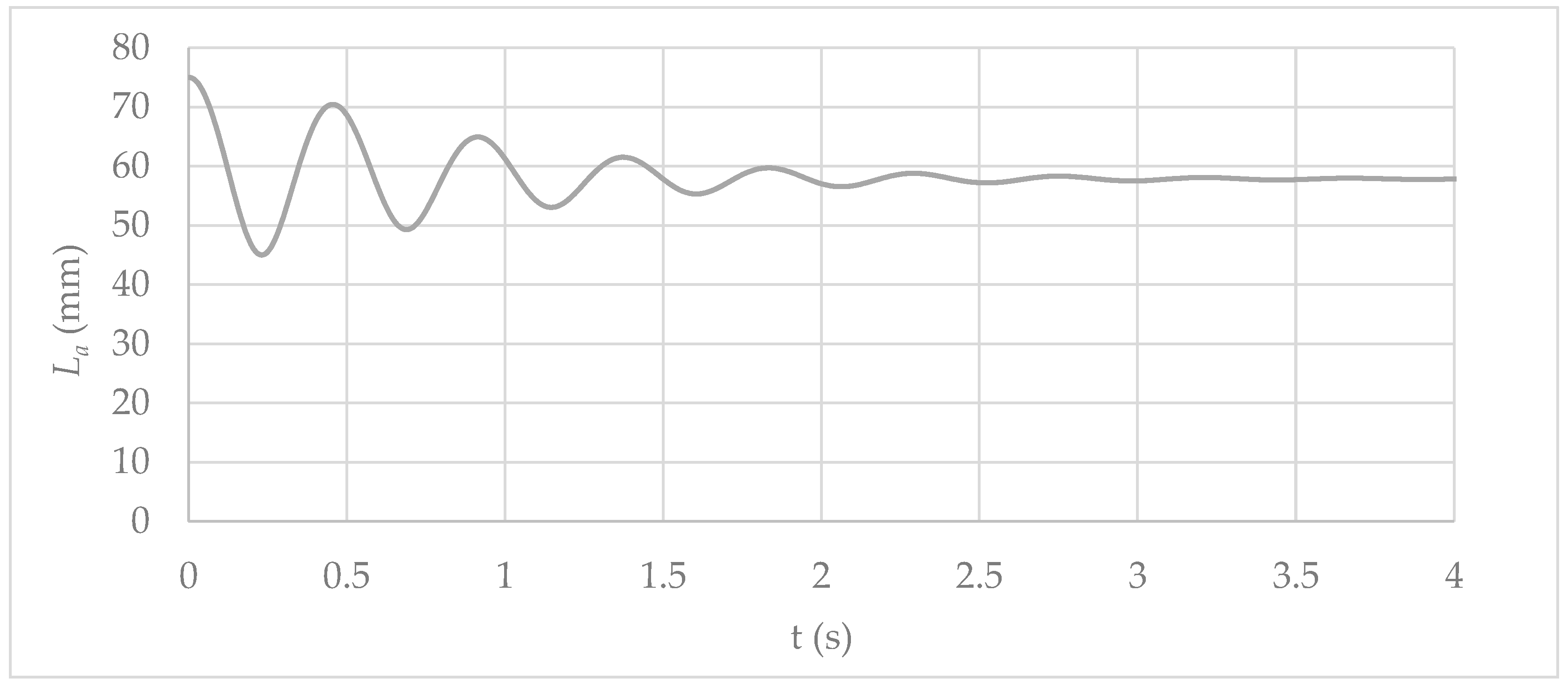
3. Model Verification

The proposed model was validated using an experimental facility at the Instituto Superior Técnico–University of Lisbon (Portugal). This validation aimed to check the air pocket pressure in a closed intermediate circular chamber with hydraulic behaviour similar to that of a circular manhole. The experimental facility comprised two pipe branches identified as L 1 and L 2 , with lengths of 3.83 and 4.24 m, respectively. The internal pipe diameter ( D u = D d ) was 51.4 mm with a friction factor of 0.020 (steady-state condition). During the analysis, an intermediate polytropic coefficient of 1.2 was considered. Figure 2 presents the configuration of the experimental facility.
The experimental setup was designed to investigate a transient event that may occur at the outlet of a pumping station in a hydraulic system with a sealed manhole (chamber), incorporating a hydro-pneumatic tank upstream. In this context, an air vessel, which exhibits behaviour similar to that of a sealed manhole, is positioned at the highest point to study pressurisation conditions.
To generate a pressurised system, all regulating valves are opened with a constant flow of 2.07 L/s. The system starts in a steady-state condition. The chamber has an internal diameter ( d M ) of 140 mm and a height of 325 mm. The chamber (manhole) begins with an initial air pocket size of 75 mm. Finally, two hydro-pneumatic tanks are placed to guarantee that the water installation is under pressure. The pressure levels of the upstream and downstream hydro-pneumatic tanks are 2 bars and 1 bar, respectively. At the beginning, the air pocket in the chamber is in an atmospheric condition. A pressure transducer S-10 WIKA was installed at the chamber’s top to record absolute air pocket pulses.
The model proposed in Section 2 neglected minor losses in the chamber and the losses provoked by a regulating valve, since these elements were not configured in the experimental facility. Figure 3 compares the mathematical model and the experimental chamber absolute pressure test. According to the results, the proposed model is suitable for representing chamber absolute pressure pulses since it follows the experimental measurement. The proposed model simulated a maximum pressure head value of 19.1 m (at 0.23 s), while the experimental test recorded a value of 18.9 m (at 0.25 s), and these are very close to each other. This is of the utmost importance, since the proposed model can fit the maximum value of the pressure head, which is crucial to assessing the structural stability of intermediate chambers (or manholes in urban drainage systems).
Air pocket size oscillations in the chamber were analysed by employing the proposed model, as shown in Figure 4. The air pocket size started with an initial value of 75 mm. After that, some fluctuations occurred since the chamber was filled with water during the transient event. The filling of the chamber caused compression of the air pocket, and then its value decreased at the end of the transient event (at 4 s) to 57.6 mm. The minimum value of the air pocket size, 44.3 mm, coincides with the peak of the chamber’s absolute pressure (at 0.23 s).
The proposed model’s only parameter is the polytropic coefficient. For this reason, a sensitivity analysis was conducted to observe its behaviour, as shown in Figure 5. An entire range was considered from 1.0 (isothermal evolution) to 1.4 (adiabatic evolution). The maximum air pocket pressure peak considering an isothermal evolution was found to have a value of 19.24 m (at 0.24 s), while with an adiabatic evolution, the maximum attained value was 18.99 (at 0.22 s). In all cases, the air pocket pressure reached 13.98 m.
Finally, the pressure of the hydro-pneumatic tank was analysed using the following relationship:
R = H T u , i H T u , r e f
where R represents the adopted relationship, H T u , r e f is the upstream hydro-pneumatic tank reference pressure used for verification purposes (2 bars), and H T u , i is the considered upstream hydrodunatic tank pressure.
The value of R varied from 0.7 to 2.0, as illustrated in Figure 6. A higher R-value corresponds to a more significant air pocket pressure head peak. For example, when employing a relationship of 0.7, a pressure peak of 11.89 m is observed, whereas using a value of 2.0 results in a maximum pressure peak of 61.30 m. As expected, after the hydraulic events, the pressure reaches 11.00 m and 23.83 m using R-values of 0.7 and 2.0, respectively.

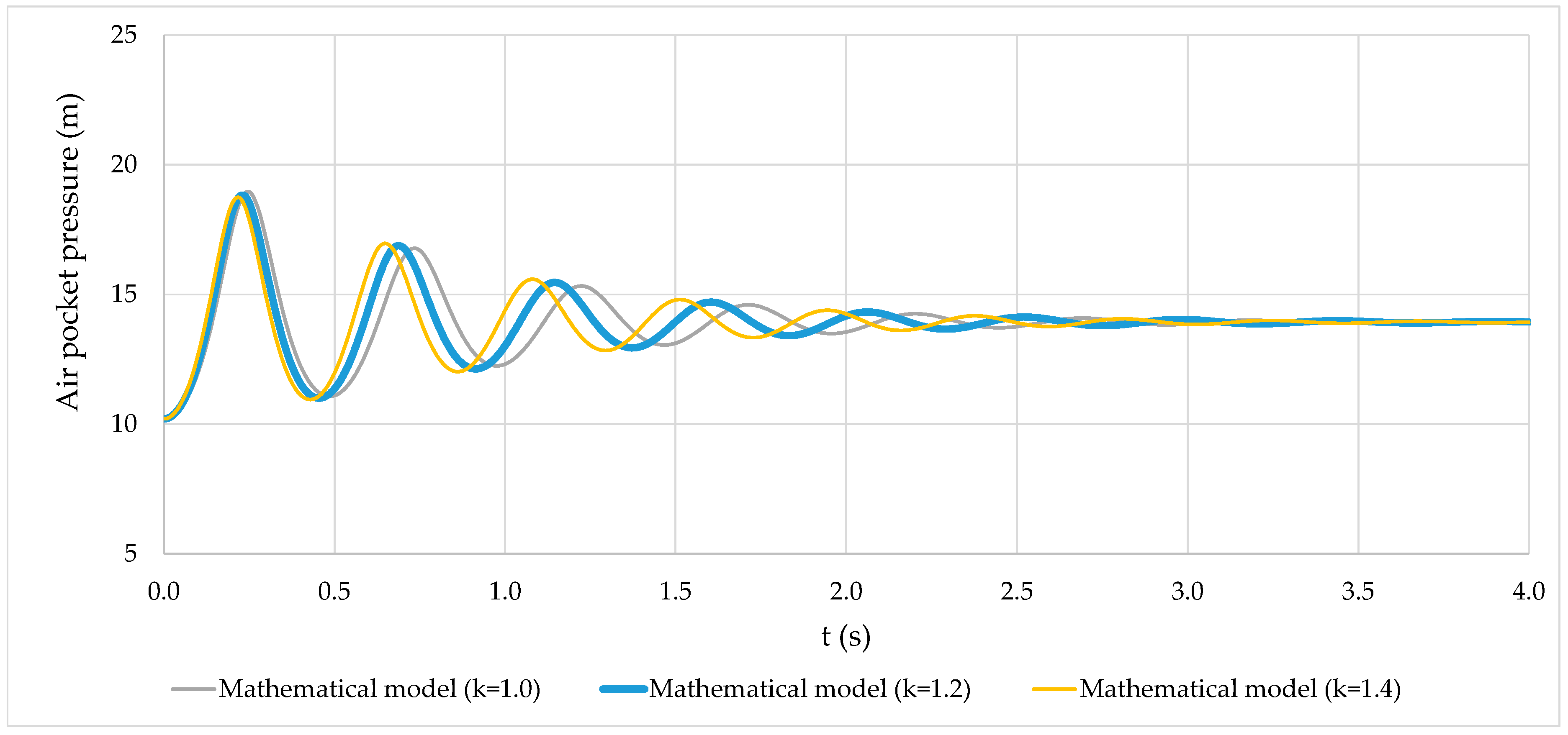
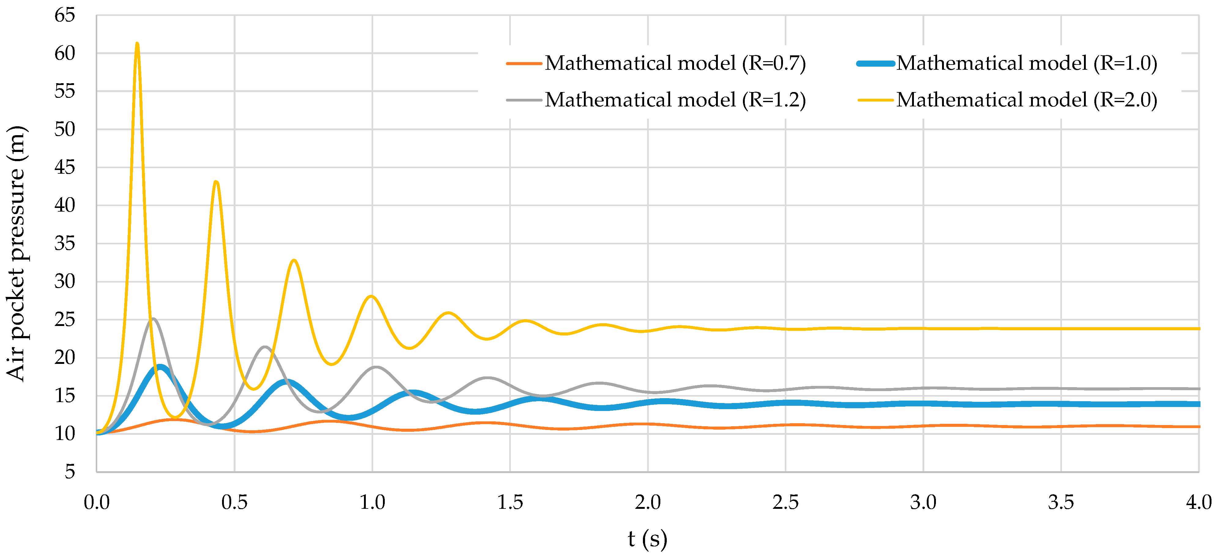
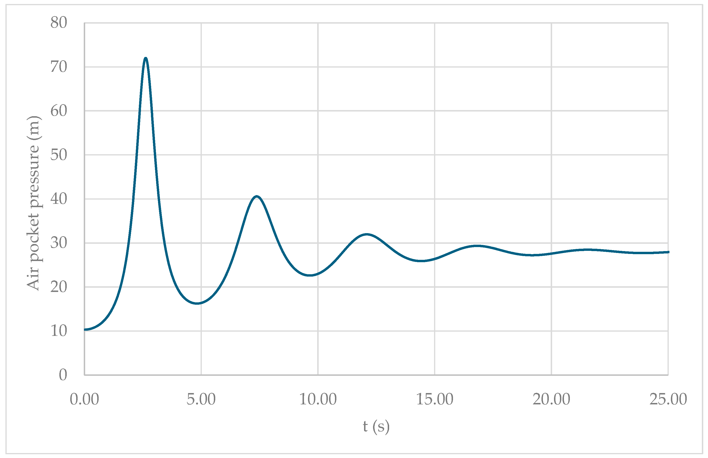
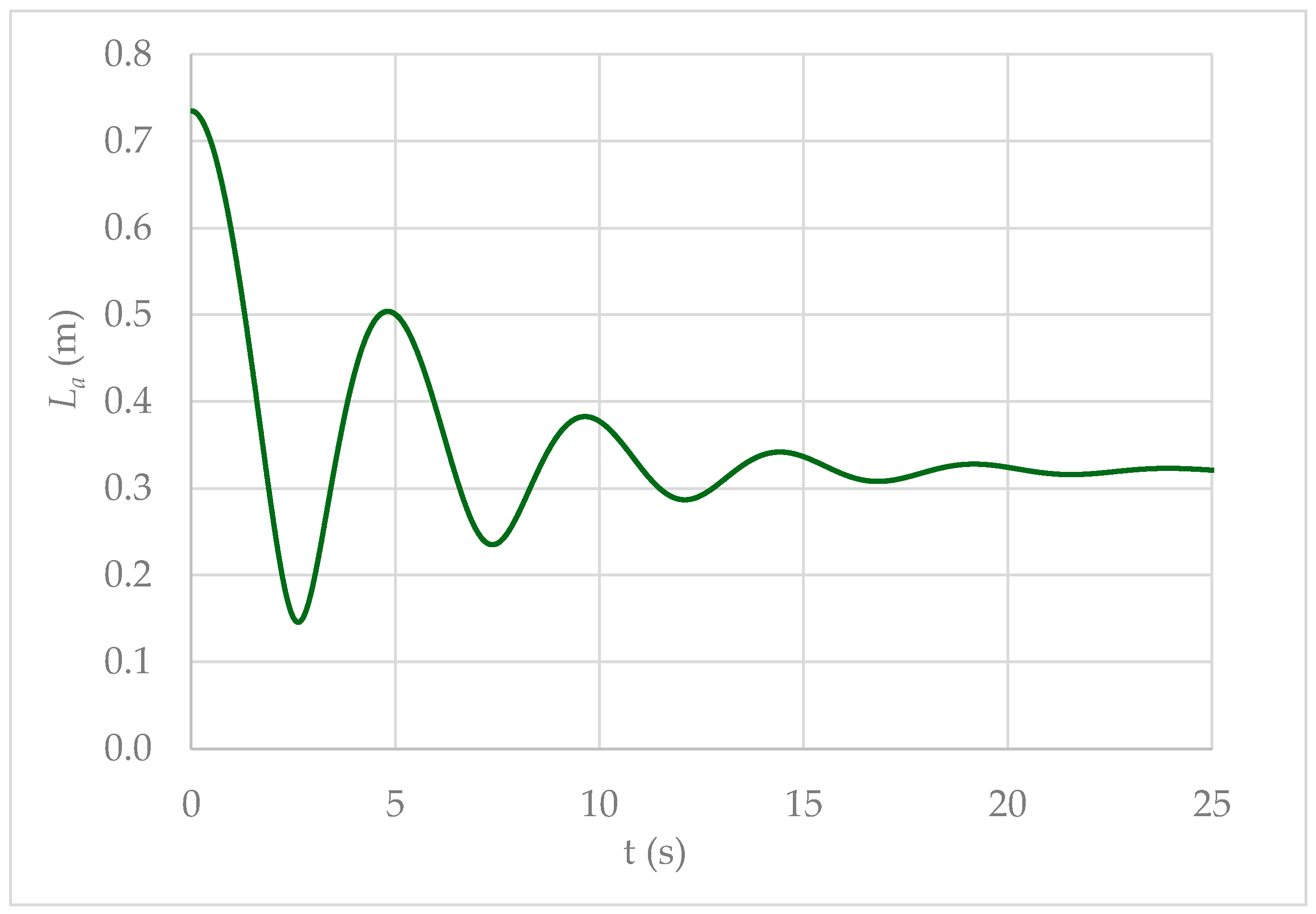
4. Case Study and Results

To illustrate the order of magnitude of the proposed model, an urban drainage system similar to that shown in Figure 1 was analysed, using the following data: D = 0.452 m, L u =130 m, L d = 70 m, d M = 1.6 m. The initial conditions are defined as Q = 480 L/s ( v = 2.99 m/s) in pipes, with an air pocket pressure of 101,325 Pa and an initial air pocket size of 0.735 m.
The configuration of the analysed system includes inverted elevations of z u = 0.50 m, z M = 19.80 m, and z d = 18.50 m. A pumping station supplies the hydraulic system with a constant head of 40 m. The outfall condition is characterised by a hydraulic control maintaining a constant water level at an elevation of 20.60 m.
For the analysis, energy losses at the junction in the sealed manhole cover were calculated using the HEC-22 method.
h m = K t v d 2 2 g
The value of K t can be calculated as follows:
K t = K 0 C b C Q C d C D C p
where K 0 = the initial head loss coefficient of a manhole, C b = the factor for benching, C Q = the factor for relative flow, C d = the factor for flow depth, C D = the factor for internal pipe diameter variations, and C p = the factor for plunging flow.
A full bench was considered when computing the head loss of the sealed manhole cover. The initial head loss coefficient was computed as K 0 = 0.1 d M D ( 1 sin Δ ) + 1.4 d M D 0.15 sin Δ , where Δ = the angle between pipe branches (0°). In this case study, K 0 = 0.1 d M D = 0.35 . The remaining coeffcients are C b = C d = C p = C D = C Q = 1.
The proposed model was employed to compute the air pocket pressure head in the case study, as shown in Figure 7. Although the initial air pocket pressure started at 10.33 m, it could increase to a maximum value of 72.01 m (at 2.63 s) due to the compression of the air phase. Subsequently, oscillations occurred, with a few peaks, until the system reached a steady-state condition.
It is of the utmost importance that the barrel and cone of the manhole be designed from a structural perspective, taking into account the maximum air pocket pressure computed by the proposed model.
The air pocket size exhibited oscillations similar to air pocket pressure pulses, as governed by the polytropic law (Equation (3)). Initially, the air pocket measured 0.735 m. By the end of the transient event, it was reduced to 0.320 m, indicating a compression of 0.415 m. Consequently, the compressed air volume within the manhole amounted to 0.83 m3 (see Figure 8).

5. Discussion

This study utilised the rigid water column theory to evaluate the water phase, as stormwater management companies do not anticipate high-pressure head values within urban drainage systems. This suggests that volumetric changes in the water phase are negligible compared to those in the air phase.
Regarding pipe and manhole elasticity, it is of utmost importance to simulate conditions where the pressure head does not exceed the resistance limits of these materials. In addition, valve closures can induce significant pressure surges, necessitating the consideration of the elastic properties of water, pipes, and manhole materials. In this regard, water suppliers should aim to operate valves as gradually as possible. The discrepancy between the rigid and elastic water column theories in terms of valve manoeuvres can be evaluated using conventional charts [31,32], which focus solely on the water phase.
Ultimately, the interaction between water and air results in the rigid and elastic column theories yielding comparable outcomes, as the elasticity of air far exceeds that of the manhole, pipe, and water [22,33], making the proposed model a suitable tool for assessing this problem.

6. Conclusions

Researchers have given limited attention to the study of air pocket pressure oscillations in sealed manhole covers (without expelling air) within sewer systems. However, this phenomenon is of significant interest to engineers and designers, as the peak pressure reached during such events can lead to surges capable of causing manhole failure if the structure has not been adequately designed to withstand the maximum air pocket pressure.
This study developed a mathematical model to analyse hydraulic events in sealed manhole covers, focusing on air phase compression induced by pumping stations in urban drainage systems. The proposed model was first validated using a 7.3 m long experimental setup. A comparison between calculated and measured air pocket pressure head pulses confirmed the model’s ability to simulate this phenomenon accurately. Moreover, the model effectively captured the peak air pocket pressure head required for the structural design of manholes. Finally, the validated model was applied to a case study to assess the impact of extreme air pocket pressure in the examined scenario.

Author Contributions

Conceptualization, A.A.-P. and O.E.C.-H.; methodology, M.P.-S., H.M.R., and O.E.C.-H.; formal analysis, J.A.M.-B.; validation, O.E.C.-H.; writing—original draft preparation, O.E.C.-H., M.P.-S. and J.A.M.-B.; writing—review and editing, H.M.R. and A.A.-P. All authors have read and agreed to the published version of the manuscript.

Funding

This research received no external funding.

Data Availability Statement

The databases used are available in this article.

Conflicts of Interest

The authors declare no conflicts of interest.

Nomenclature

The following abbreviations are employed in this article:
A d cross-sectional area of a conduit located at the downstream end of the sealed manhole cover (m2);
C b factor for benching (-);
C d factor for flow depth (-);
C D factor for internal pipe diameter variations (-);
C Q factor for relative flow (-);
C p factor for plunging flow (-);
d M manhole diameter (m);
D u internal pipe diameter of the upstream counduit (m);
f friction factor of a pressurised conduit (-);
g gravitational acceleration (m/s2);
h m manhole head loss (m);
H T u , i considered upstream hydrodunatic tank pressure (m);
H T u , r e f upstream hydro-pneumatic tank reference pressure (m);
k polytropic coefficient (-);
K 0 initial head loss coefficient in a manhole (-);
K t manhole head loss coefficient (-);
h d water level at the outfall (m);
h u upstream water level supplied by a pump or from another conduit (m);
L a air pocket length (m);
L d conduit length located at the downstream end of the sealed manhole cover (m);
L u conduit length located at the upstream end of the sealed manhole cover (m);
p a , M * air pocket absolute pressure in the sealed manhole cover (Pa);
R relationship between hydro-pneumatic tank pressure and reference pressure (-);
R v resistance coefficient of a discharge valve (ms2/m6);
V d water velocity of a conduit located at the downstream end of the sealed manhole cover (m/s);
V u water velocity of a conduit located at the upstream end of the sealed manhole cover (m/s);
z d inverted elevation in a manhole located at the downstream end of the sealed manhole cover (m);
z M inverted elevation in the sealed manhole cover (m);
z u inverted elevation in a manhole located at the upstream end of the sealed manhole cover (m);
a , M air volume (m3);
T , M total volume of a manhole (m3);
w , M water volume inside of the sealed manhole cover (m3);
ρ w water density (kg/m3);
γ w water unit weight (N/m3);
0an initial condition (-).

References

  1. Chow, V.T. Open-Channel Hydraulics; McGraw-Hill: Tokyo, Japan, 1959. [Google Scholar]
  2. Theodor, S. Numerical Solution of Saint-Venant Equations. J. Hydraul. Div. 1970, 96, 223–252. [Google Scholar] [CrossRef]
  3. Cheng, X.; Wang, H.; Chen, B.; Li, Z.; Zhou, J. Comparative Analysis of Flood Prevention and Control at LID Facilities with Runoff and Flooding as Control Objectives Based on InfoWorks ICM. Water 2024, 16, 374. [Google Scholar] [CrossRef]
  4. Gopi, K.V.; Anish, N.; Reddy, A.H.; Sanjay, P.; Datta, K.P.; Vaishnavi, B. Assessment of Water Surcharge Conditions in an Urban Area Using SEWERGEMS: A Case Study. In Advances in Environmental Sustainability, Energy and Earth Science; Pathak, P., Ilyas, S., Srivastava, R.R., Dar, J., Kothandaraman, S., Eds.; Springer Nature: Cham, Switzerland, 2024; pp. 311–318. [Google Scholar]
  5. Hodges, B.R.; Sharior, S.; Tiernan, E.D.; Jenkins, E.; Riaño-Briceño, G.; Davila-Hernandez, C.; Madadi-Kandjani, E.; Yu, C.-W. Introducing SWMM5+. J. Environ. Eng. 2024, 150, 02524003. [Google Scholar] [CrossRef]
  6. Ferreira, J.P.; Ferràs, D.; Covas, D.I.C.; van der Werf, J.A.; Kapelan, Z. Air Entrapment Modelling during Pipe Filling Based on SWMM. J. Hydraul. Res. 2024, 62, 39–57. [Google Scholar] [CrossRef]
  7. Butler, D.; Digman, C.; Makropoulos, C.; Davies, J.W. Urban Drainage, 4th ed.; CRC Press: Boca Raton, FL, USA, 2018; ISBN 1351174304. [Google Scholar]
  8. Bourdarias, C.; Gerbi, S. A Finite Volume Scheme for a Model Coupling Free Surface and Pressurised Flows in Pipes. J. Comput. Appl. Math. 2007, 209, 109–131. [Google Scholar] [CrossRef]
  9. Hager, W.H. Standard Manhole. In Wastewater Hydraulics: Theory and Practice; Hager, W.H., Ed.; Springer: Berlin/Heidelberg, Germany, 2010; pp. 379–388. ISBN 978-3-642-11383-3. [Google Scholar]
  10. Rubinato, M.; Martins, R.; Shucksmith, J.D. Quantification of Energy Losses at a Surcharging Manhole. Urban Water J. 2018, 15, 234–241. [Google Scholar] [CrossRef]
  11. Ramos, H.M.; Pérez-Sánchez, M.; Franco, A.B.; López-Jiménez, P.A. Urban Floods Adaptation and Sustainable Drainage Measures. Fluids 2017, 2, 61. [Google Scholar] [CrossRef]
  12. Vasconcelos, J.G.; Wright, S.J. Experimental Investigation of Surges in a Stormwater Storage Tunnel. J. Hydraul. Eng. 2005, 131, 853–861. [Google Scholar] [CrossRef]
  13. Vasconcelos, J.G.; Klaver, P.R.; Lautenbach, D.J. Flow Regime Transition Simulation Incorporating Entrapped Air Pocket Effects. Urban Water J. 2015, 12, 488–501. [Google Scholar] [CrossRef]
  14. Khani, D.; Lim, Y.H.; Malekpour, A. A Mixed Flow Analysis of Sewer Pipes with Different Shapes Using a Non-Oscillatory Two-Component Pressure Approach (TPA). Modelling 2021, 2, 467–481. [Google Scholar] [CrossRef]
  15. Vasconcelos, J.G.; Wright, S.J. Geysering Generated by Large Air Pockets Released through Water-Filled Ventilation Shafts. J. Hydraul. Eng. 2011, 137, 543–555. [Google Scholar] [CrossRef]
  16. Liu, J.; Qian, Y.; Zhu, D.Z.; Zhang, J.; Edwini-Bonsu, S.; Zhou, F. Numerical Study on the Mechanisms of Storm Geysers in a Vertical Riser-Chamber System. J. Hydraul. Res. 2022, 60, 341–356. [Google Scholar] [CrossRef]
  17. Allasia, D.G.; Böck, L.É.; Vasconcelos, J.G.; Pinto, L.C.; Tassi, R.; Minetto, B.; Persch, C.G.; Pachaly, R.L. Experimental Study of Geysering in an Upstream Vertical Shaft. Water 2023, 15, 1740. [Google Scholar] [CrossRef]
  18. Chan, S.N.; Cong, J.; Lee, J.H. 3D Numerical Modeling of Geyser Formation by Release of Entrapped Air from Horizontal Pipe into Vertical Shaft. J. Hydraul. Eng. 2018, 144, 04017071. [Google Scholar] [CrossRef]
  19. Zhou, L.; Pan, T.; Wang, H.; Liu, D.; Wang, P. Rapid Air Expulsion through an Orifice in a Vertical Water Pipe. J. Hydraul. Res. 2019, 57, 307–317. [Google Scholar] [CrossRef]
  20. Paternina-Verona, D.A.; Coronado-Hernández, O.E.; Espinoza-Román, H.G.; Arrieta-Pastrana, A.; Tasca, E.; Fuertes-Miquel, V.S.; Ramos, H.M. Attenuation of Pipeline Filling Over-Pressures through Trapped Air. Urban Water J. 2024, 21, 698–710. [Google Scholar] [CrossRef]
  21. Zhou, L.; Lu, Y.; Karney, B.; Wu, G.; Elong, A.; Huang, K. Energy Dissipation in a Rapid Filling Vertical Pipe with Trapped Air. J. Hydraul. Res. 2023, 61, 120–132. [Google Scholar] [CrossRef]
  22. Fuertes-Miquel, V.S.; Coronado-Hernández, O.E.; Mora-Meliá, D.; Iglesias-Rey, P.L. Hydraulic Modeling during Filling and Emptying Processes in Pressurized Pipelines: A Literature Review. Urban Water J. 2019, 16, 299–311. [Google Scholar] [CrossRef]
  23. Wang, J.; Vasconcelos, J.G. Manhole Cover Displacement Caused by the Release of Entrapped Air Pockets. J. Water Manag. Model. 2018, 2018, 1–6. [Google Scholar] [CrossRef]
  24. Apollonio, C.; Balacco, G.; Fontana, N.; Giugni, M.; Marini, G.; Piccinni, A.F. Hydraulic Transients Caused by Air Expulsion During Rapid Filling of Undulating Pipelines. Water 2016, 8, 25. [Google Scholar] [CrossRef]
  25. Romero, G.; Fuertes-Miquel, V.S.; Coronado-Hernández, Ó.E.; Ponz-Carcelén, R.; Biel-Sanchis, F. Analysis of Hydraulic Transients during Pipeline Filling Processes with Air Valves in Large-Scale Installations. Urban Water J. 2020, 17, 568–575. [Google Scholar] [CrossRef]
  26. Ma, S.; Zayed, T.; Xing, J.; Shao, Y. A State-of-the-Art Review for the Prediction of Overflow in Urban Sewer Systems. J. Clean. Prod. 2024, 434, 139923. [Google Scholar] [CrossRef]
  27. Martin, C.S. Entrapped Air in Pipelines. In Proceedings of the 2nd International Conference on Pressure Surges, London, UK, 22–24 September 1976. [Google Scholar]
  28. Zhou, F. Effects of Trapped Air on Flow Transients in Rapidly Filling Sewers. Ph.D Dissertation, University of Alberta, Edmonton, AL, Canada, 2000. [Google Scholar]
  29. Wright, S.J.; Determan, K.V.; Vargas, S.M. Pressure Transients Due to Compression of Trapped Air in Rapidly Filling Sewer Storage Tunnels. J. Water Manag. Model. 2012, 20, 1–20. [Google Scholar] [CrossRef]
  30. Wang, J.; Vasconcelos, J.G. Investigation of Manhole Cover Displacement during Rapid Filling of Stormwater Systems. J. Hydraul. Eng. 2020, 146, 4020022. [Google Scholar] [CrossRef]
  31. Wood, F.M. Comparison of the Rigid Column and Elastic Theories for Waterhammer. In Proceedings of the First Canadian Hydraulics Conference, Edmonton, AL, Canada, 10–11 May 1973. [Google Scholar]
  32. Abreu, J.; Cabrera, E.; Izquierdo, J.; García-Serra, J. Flow Modeling in Pressurized Systems Revisited. J. Hydraul. Eng. 1999, 125, 1154–1169. [Google Scholar] [CrossRef]
  33. Zhou, L.; Liu, D.; Karney, B. Investigation of Hydraulic Transients of Two Entrapped Air Pockets in a Water Pipeline. J. Hydraul. Eng. 2013, 139, 949–959. [Google Scholar] [CrossRef]
Figure 1. A schematic of an entrapped air pocket within a sealed manhole cover: (a) profile view; (b) the initial position of the entrapped air pocket; and (c) the intermediate position of the entrapped air pocket.
Water 17 00984 g001
Figure 2. A schematic of the experimental setup.
Water 17 00984 g002
Figure 3. A comparison between the mathematical model and the experimental test in a chamber of absolute pressure.
Water 17 00984 g003
Figure 4. Air pocket size oscillations in the experimental facility.
Water 17 00984 g004
Figure 5. Sensitivity analysis of the polytropic coefficient.
Water 17 00984 g005
Figure 6. Analysis of the upstream hydro-pneumatic tank pressure.
Water 17 00984 g006
Figure 7. Air pocket pressure head pulses of the case study.
Water 17 00984 g007
Figure 8. Air pocket size oscillations of the case study.
Water 17 00984 g008
Disclaimer/Publisher’s Note: The statements, opinions and data contained in all publications are solely those of the individual author(s) and contributor(s) and not of MDPI and/or the editor(s). MDPI and/or the editor(s) disclaim responsibility for any injury to people or property resulting from any ideas, methods, instructions or products referred to in the content.

