Article

Insights into the Hydraulic Characteristics of Critical A-Jumps for Energy Dissipator Design

1
POWERCHINA Kunming Engineering Corporation Limited, Kunming 650033, China
2
College of Harbour and Coastal Engineering, Jimei University, Xiamen 361021, China
*
Author to whom correspondence should be addressed.
Water 2025, 17(7), 960; https://doi.org/10.3390/w17070960
Submission received: 23 February 2025 / Revised: 19 March 2025 / Accepted: 23 March 2025 / Published: 25 March 2025

Abstract

:
Hydraulic jumps are widely used to dissipate excess energy in civil, ocean, and hydro-power engineering, particularly in high dams with large reservoirs. Different inflow and tailwater conditions lead to the occurrence of various types of hydraulic jumps. Among them, A-jumps are often preferred for stilling basin design, due to their high energy dissipation efficiency and favorable outflow patterns. This study numerically investigated the hydraulic characteristics of 75 critical A-jumps by adjusting tailwater levels, considering varying inflow conditions (flow depth, velocity, discharge, and Froude number) and stilling basin parameters (negative step height and incident angle), covering key parameter ranges from existing practical applications in high dam projects. Based on theoretical analysis and numerical simulations, estimation methods are proposed for the key hydraulic parameters of A-jumps, including the sequent depth ratio, roller length, reattachment length, and energy dissipation rate. A correction for the sequent depth ratio, incorporating the influence of the incident angle, is proposed for the first time. These estimation methods offer valuable insights for designing and optimizing negative step stilling basins in various practical engineering scenarios. To validate their applicability, a case study was conducted, showcasing the superior energy dissipation and stable outflow performance of the designed stilling basin, with the basin length shortened by 1.8% and the near-bottom velocity reduced by 42.4%, based on the proposed estimations, compared to the classical stilling basin.

1. Introduction

Utilizing the turbulent characteristics of hydraulic jumps for energy dissipation is a well-established and effective method, widely employed in hydropower, civil, and ocean engineering. This approach is commonly integrated into outfall structures, such as spillways in high dam hydropower projects [1,2,3,4], storm discharge systems in coastal cities [5], desalination brine discharge systems [6], and sewage outfalls [7]. On the one hand, hydraulic jumps effectively dissipate excess energy, enhancing the stability and ecological safety of outflows, as illustrated in Figure 1. On the other hand, the highly energetic and complex flow conditions can lead to adverse effects, such as bed erosion and structural damage. Therefore, precise control of hydraulic jumps is crucial in the design of outfall structures. Among these measures, negative step stilling basins have become widely used, offering notable advantages, especially in recent hydropower projects that have significant height differences and high discharge capacities. Table 1 presents practical applications of negative step stilling basins, illustrating their growing adoption in real-world projects. However, the complex flow characteristics of these hydraulic jumps remain insufficiently understood, and widely accepted design methodologies for negative step stilling basins are still lacking. Parameter selection for negative step stilling pools often relies on simplified theoretical analyses or empirical formulas, which may be inadequate for complex engineering scenarios due to the challenge of determining key characteristic parameters, resulting in limited practical applicability. Addressing these gaps is essential to ensure structural safety and maximize energy dissipation efficiency.
The flow characteristics of hydraulic jumps in negative step stilling basins are complex and influenced by various factors, including step height, incident angle, discharge, and tailwater level. According to Hager and Bretz [8], as the downstream tailwater level decreases, different types of hydraulic jump behavior emerge sequentially, including A-jumps, downward-curved jets, wave-jumps, B-jumps, upward-curved jets, and minimum B-jumps. These variations in hydraulic jump behavior significantly impact both the energy dissipation efficiency and outflow stability. Among these, the A-jump is preferred in engineering applications due to its superior energy dissipation capacity and stable outflow characteristics [1,9]. The generation of critical A-jumps is often used as a design target for negative step stilling basins, which is defined as a scenario where the jump toe is located upstream of the negative step, followed by a surface roller (as shown in Figure 2). A-jumps feature an upstream-directed roller and recirculating vortex, promoting rapid energy dissipation. Compared to classical jumps in flat-bottomed channels, A-jumps achieve higher turbulence and energy loss over a shorter distance, making them particularly effective in preventing downstream erosion and structural damage. Understanding the hydraulic characteristics of critical A-jumps, particularly their characteristic parameters, is essential for designing practical negative step stilling basins.
The key characteristics of hydraulic jumps, such as the sequent depth ratio, roller length, and reattachment length, are critical considerations in stilling basin design. The sequent depth ratio is particularly important, as it directly influences energy dissipation efficiency. Theoretical analyses based on momentum conservation in classical hydraulic jumps within flat-bottomed, rectangular open channels have established relationships between the sequent depth ratio, inflow conditions (e.g., Froude number), and step height, to guide the design of stilling basins [8,10,11]. To account for different types of hydraulic jumps in basins of varying shapes, correction coefficients have been incorporated into these relationships [12,13]. Additionally, two key length parameters—roller length and reattachment length—further influence stilling basin dimensions [14]. The roller length ( L r ) is defined as the distance from the jump head to the stagnation point of the surface velocity, while the reattachment length ( L e ) extends from the step to the jet impact point at the bottom, as illustrated in Figure 2. These characteristic parameters are commonly estimated using empirical formulas [15,16,17,18] derived from experimental studies, making them accurate only under specific and constrained conditions. Their applicability in complex and dynamic engineering scenarios remains limited, highlighting the need for further refinement and validation. Moreover, existing studies commonly overlooked the influence of incident angle on the key characteristics of hydraulic jumps. In summary, accurately assessing these key characteristics is essential for improving stilling basin design, ensuring structural efficiency and safety. However, current evaluation methods primarily rely on simplified theoretical analyses or limited experimental data, have a narrow scope of application, and largely neglect the influence of the incident angle.
In this study, the hydraulic characteristics of critical A-jumps are numerically investigated through 75 cases with varying step heights, incident angles, and inflow Froude numbers, covering key parameter ranges from existing hydropower projects. The numerical model is based on 2-D Navier–Stokes equations, fully accounting for turbulence using the RNG k-ε turbulence model, which has gained increasing attention for providing valuable dynamic insights [9,19,20,21]. Based on theoretical and numerical studies, advanced estimations are proposed for the key parameters of critical A-jumps, including sequent depth ratio, roller length, reattachment length, and corresponding energy dissipation rate. These estimations aim to improve the design of negative step stilling basins by accounting for the wide range of engineering scenarios and key parameter variations observed in existing projects. The influence of the incident angle on these parameters is quantitatively evaluated, enhancing the accuracy and applicability of basin designs across diverse real-world conditions.
Table 1. Representative high dam hydropower projects that employ a negative step stilling basin to dissipate exceed energy [22].
No.ProjectsDam Height
(m)
Design Discharge
(m3/s)
Step Height
(m)
Country
1Xiangjiaba162.041,2009.0China
2Huangjinping95.55650-China
3Jin’anqiao160.011,668-China
4Guanyinyuan159.016,9007.5China
5Liyuan155.011,36115.8China
6Guandi168.014,0006.5China
7Tingzikou110.034,5008.0China
8Myitsone139.5-8.0Burma
9Sayano-Shushenskaya242-4.2–6.0Russia
10TaSang Dam227.5--Burma

2. Numerical Model

2.1. Governing Equations

In the present study, the dynamic characteristics of critical A-jumps in a negative step stilling basin are analyzed using the two-dimensional unsteady incompressible Reynolds-averaged Navier–Stokes (2-D RANS) equations [23]:
u i ¯ x i = 0
u i ¯ t + u j ¯ u i ¯ x j = 1 ρ p - x i + ν 2 u i ¯ x i x j + 1 ρ τ i j x j +   f i ¯
where x i and x j denote the coordinates. Subscripts i and j represent the two coordinate directions, which obey the Einstein summation convention. u i ¯ and u j ¯ are the time-averaged velocity components. t denotes the time. ρ is the fluid density. p - is the time-averaged pressure. ν is the fluid kinematic viscosity. f i ¯ is the body forces. τ i j is the Reynolds stress tensor, defined as τ i j = ρ u i u j ¯ . Based on the Boussinesq eddy-viscosity assumption [24], the Reynolds stress tensor τ i j is as follows:
τ i j = ρ u i u j ¯ = μ t u i ¯ x j + u j ¯ x i 2 3 δ i j ρ k
where μ t is the turbulent viscosity, δ i j is the Kronecker delta and, k is the turbulent kinetic energy. u i u j ¯ represents the time-averaged product of the fluctuating velocities. To determine the turbulent viscosity μ t , the RNG k-ε turbulence model is employed in this study. It has been validated as effective in capturing the influence of small-scale vortices, offering higher accuracy in simulating flows with intense turbulence, instantaneous fluctuations, and low Reynolds numbers compared to the standard k-ε model [19,25]. The RNG k-ε turbulence model calculates the turbulent viscosity through the kinetic energy k and its dissipation ε, as follows [26]:
μ t = ρ C μ k 2 ε
where C μ is the turbulence constant, and C μ = 0.09 is adopted. The k -equation and ε -equation of the RNG k - ε turbulence model are as follows [27]:
( ρ k ) t + ( ρ k u i ¯ ) x i = x j ( μ + μ t / σ k ) k x j + G k ρ ε
( ρ ε ) t + ( ρ ε u i ¯ ) x i = x j ( μ + μ t / σ ε ) ε x j + C 1 ε ε k G k C 2 ε ρ ε 2 k R
where μ is the molecular viscosity, μ t is the turbulent viscosity, and σ k and σ ε are the turbulent Prandtl numbers for k and ε, respectively. G k is the generation of turbulent kinetic energy due to mean velocity gradient, given by G k = ρ u i u j ¯ u i ¯ / x j . In this study, the values of the coefficients are adopted as C 1 ε = 1.42 , C 2 ε = 1.68 , σ k = 0.7194 , and σ ε = 0.7194 , referring to Koutsourakis et al. [28]. The R in Equation (6) is expressed as:
R = ρ C μ ξ 3 1 ξ / ξ 0 1 + ω ξ 3 ε 2 k
where ξ is the relative strain parameter, ξ = S ¯ k / ε . S ¯ is the mean strain rate. ξ 0 and ω are coefficients with ξ 0 = 4.38 and ω = 0.012 [27].
The governing equations were solved using ANSYS FLUENT Academic v.20.0, a widely used computational fluid dynamics tool. The Volume of Fluid (VOF) method was employed to simulate the interface between air and water [24]. This method treats water and air as a single mixture by solving a set of Navier–Stokes equations, incorporating an additional variable, known as volume fraction of water ( α ) to accurately capture the free water surface. The basic form of the VOF model is as follows [29]:
α t + x i α u i = 0
in which, a value of a = 1 indicates that the grid cell is completely filled with water, while a = 0 signifies that it is entirely filled with air. For values between 0 and 1, the grid cell contains a mixture of water and air. In this study, the free water surface is defined as the location where a = 0.5 [20].

2.2. Numerical Setting

To validate the numerical model and investigate the sensitivity of the numerical mesh, the experiment conducted by Simsek et al. [30] was reproduced, which is shown in Figure 3. The computational domain aligned with the experimental setup, with dimensions of 1.7 m in length and 0.2 m in depth. The step height was set to be s = 0.097   m , and the tailwater depth was regulated by a sharp-crested weir with a fixed height of h 3 = 0.06   m at the end of the channel. Boundary conditions for the numerical simulation matched those of the experiments. At the inlet boundary, the water depth was h 1 = 0.023   m , and the depth-averaged flow velocity was U 1   = 0.663   m / s . No-slip boundary conditions were applied to the side and bottom walls, with the flow near the walls treated using standard wall functions. The top and outlet of the computational domain were defined as pressure outlet boundaries. Since this study focuses solely on 2D flow dynamics, the numerical model is applicable only to hydraulic jump simulations in a stilling basin with a uniform rectangular cross-section in the transverse direction. It is not suitable for cases involving sudden widening or narrowing in the transverse direction, where strong three-dimensional hydrodynamic effects play a significant role.
The pressure–velocity coupling was handled using the Pressure-Implicit with Splitting of Operators (PISO) algorithm, with a second-order upwind scheme for momentum discretization and a first-order implicit scheme for time discretization [31]. The Courant number was used to determine the convergence condition, which is defined as u Δ t / Δ x , where u denotes the flow velocity and Δ x is the grid size. The CFL number was 5.0 in this study. Considering the convergence condition, the time step was set to t = 0.0001   s . To evaluate the influence of mesh size on simulation accuracy, three mesh resolutions were tested: fine (Mesh1), medium (Mesh2), and coarse (Mesh3), containing 31,574, 18,417, and 7654 grid elements, respectively. The minimum grid sizes were 2 mm, 3 mm, and 4 mm for Mesh 1, Mesh 2, and Mesh 3, respectively. Local mesh refinement treatment was applied, particularly near the bottom region. A boundary layer grid with 10 layers of specified thickness was implemented at the bottom. After iterative calculations and adjustments, the positioning of the first layer of grid nodes was optimized to fall within the logarithmic law layer ( 11.5 ~ 30 < y + < 200 ~ 400 ), satisfying the requirements of the standard wall functions.
This study employed the Grid Convergence Index (GCI) to assess the influence of grid size on the computed results. The GCI analysis indicated that Mesh 1 exhibited the lowest uncertainty in simulated water depth, measuring below 0.84% (±0.0008 m), demonstrating a high simulation accuracy. Table 2 also summarizes the relative errors (RE) of the water surface elevation ( η ) using different grid schemes compared to the observed values. The mean RE values were 0.83%, 1.07%, and 1.77% for Mesh1, Mesh2, and Mesh3, respectively, highlighting the superior performance of the Mesh1 scheme in capturing the free water surface. Figure 4 also compares the computed free water surface elevation using the fine mesh scheme (Mesh1), with the observed results showing good agreement. The mean absolute percentage error (MAPE) and the determination coefficient ( R 2 ) between the computed (Mesh1) and observed water surface profiles were 1.59% and 0.97, respectively, indicating high simulation accuracy. These results demonstrate the good performance of the numerical model with these settings for simulating highly dynamic flows. Therefore, Mesh1 scheme was used for the remaining numerical studies.

2.3. Numerical Experiment Design

Based on the validation and mesh sensitivity study, a total of 75 cases were numerically investigated to analyze the hydraulic characteristics of A-jumps in negative step stilling basins under various inflow conditions. The influence of configurational variables (negative step height s and the incident angle θ ), as well as inflow conditions (mean inflow depth h 1 , mean inflow velocity U 1 , flow discharge per unit width q , and inflow Froude number F r 1 ) was considered. To account for as many practical situations in engineering projects as possible, the value ranges of these variables were based on a summary of commonly used parameters in hydropower engineering. Specifically, the dimensionless step height ( S   = s / h 1 ) ranged from 0.83 to 10.00, the incident angle ( θ ) varied between 0 ° and 20 ° , and the inflow Froude number ( F r 1 ) spanned from 5.6 to 11.3. The settings of the studied numerical cases are summarized in Table A1 in Appendix A. The height of the downstream sharp-crested weir was adjusted to control the tailwater level, ensuring the occurrence of critical A-jumps in the negative step stilling basin. This adjustment ensured that the jump toe precisely aligned with the step location with sufficient surface rollers. The hydraulic characteristics and energy dissipation rate of the critical A-jumps were then quantitatively discussed to provide accurate estimations of the sequent depth ratio required to trigger A-jumps, as well as other key hydraulic characteristics. These insights can help inform the design of negative step stilling basins in engineering applications.

3. Results

3.1. Sequent Depth Ratio

The sequent depth ratio of A-jumps was theoretically analyzed based on the momentum conservation. As shown in Figure 2, sections S1 and S2 represent the beginning and end of the hydraulic jump, respectively. The momentum equation, considering the influcence of the incident angle, can be expressed as follows:
γ g q β 2 U 2   β 1 U 1 cos θ = F
where γ is the volumetric weight of water. g is the gravity acceleration. q is the discharge per unit width. U 1 and U 2 are the depth averaged velocities at sections S1 and S2, with U 1 = q / h 1 and U 2 = q / h 2 , respectively. h 1 is the mean flow depth at section S1. h 2 is the sequent depth at the section S2. β 1 and β 2 are the momentum correction factors, and in this study, it was assumed that β 1 =   β 2 = 1 . θ is the incident angle. F is the sum of the external forces along the flow direction between S1 and S2.
The sequent depth ratio Y is defined as Y = h 2 / h 1 . The inflow Froude number F r 1 is defined as F r 1 = U 1 / g h 1 . Then, the relationship between the inflow Froude number and characteristic variables are
F r 1 2 = 1 γ h 1 2 ( Y 1 Y cos θ ) F
in which F can be written as follows:
F = P 1 cos θ P 2 + P a
where P 1 and P 2 are hydraustatic pressures at sections S1 and S2, respectively, and P a is the total pressure exerted on the flow by the negative step. According to Hager [32], the pressure P a on the negative step surface is assumed to follow a hydrostatic pressure distribution. Thus, P 1 , P 2 , and P a can be written as follows:
P 1 = 1 2 γ h 1 2 cos θ
P 2 = 1 2 γ h 2 2
P a = 1 2 γ s 2
where s is the step height.
Then, Equation (10) becomes
F r 1 2 = 1 γ h 1 2 ( Y 1 Y cos θ ) ( 1 2 γ h 1 2 cos 2 θ   + 1 2 γ s 2   1 2 γ h 2 2 )
After simplifying, Equation (15) can be presented as follows:
F r 1 2 = 1 2 ( Y 1 Y cos θ ) ( cos 2 θ   + S 2 Y 2 )
where S is the dimensionless step height, defined as S = s / h 1 . Equation (16) represents the theoretical sequent depth equation for the critical A-jumps in a negative step stilling basin with the incident angle θ . When S   = 0 and θ   = 0 , Equation (16) reduces to equations for a flat-bottomed horizontal jet hydraulic jump (CHJ-classical hydraulic jump).
Figure 5 illustrates the relationships between the theoretical sequent depth ratio ( Y ) of the critical A-jumps using Equation (16) and the inflow Froude number ( F r 1 ), with a varying dimensionless step height ( S ) and incident angle ( θ ), which exhibit clear trends. For a given F r 1 and θ , the sequent depth ratio Y increases as the dimensionless step height ( S ) rises. However, this growth becomes less pronounced as F r 1 increases. In other words, as F r 1 increases, the difference in Y values across varying S gradually diminishes. Upon comparing subplots (a–e) and referring to Equation (16), it is observed that for 2.5   <   S     10.0 , the influence of θ on Y is minimal and can be disregarded.
Figure 6 further validates the accuracy of Equation (16) by comparing its predictions with the numerical results. Additionally, experimental data from Hager and Bretz [6] and Mossa et al. [16] are included for further verification. Overall, for 2.5   <   S     10.0 , the results (including the experimental data) show excellent agreement, with a coefficient of determination R 2 = 0.99 , and a mean absolute percentage error (MAPE) of 3.62%. This demonstrates the reliability of Equation (16) in predicting the sequent depth ratio for critical A-jumps.
However, for stilling basins with a smaller dimensionless negative step height ( 0.833     S     2.50 ), the incident angle ( θ ) has a significant influence on the sequent depth ratio. Specifically, as θ increases, the sequent depth ratio calculated by Equation (16) increasingly deviates from the values computed by the numerical model. This phenomenon occurs because, when the negative step height is small, the incident angle significantly affects the energy dissipation. A steeper angle enhances the momentum transfer to the lower layer, increasing turbulence and jump intensity, while a shallower angle weakens the jump or shifts it downstream. In contrast, when the step height is large, the falling jet acquires substantial vertical momentum, making impact dynamics the dominant factor. Consequently, jump formation is primarily governed by step height and downstream tailwater conditions, rather than the upstream incident angle. To address this discrepancy, a correction factor ( φ ) was introduced to account for the effect of the incident angle on Y when the dimensionless negative step height is relatively low ( 0.833     S     2.50 ). This correction factor enhances the applicability of Equation (16) for estimating the sequent depth ratio of critical A-jumps across a wider range of conditions and is expressed as follows:
φ = Y * / Y
where Y represents the theoretical sequent depth ratio calculated by Equation (16). Y * is the value computed by the numerical model.
Then, the relationship between the incident angle ( θ ) and the correction factor ( φ ) is illustrated in Figure 7. When the dimensionless step heights ranged from 2.5 to 10.0, the influence of θ on Y was negligible, resulting in φ   = 1 . However, for smaller dimensionless step heights ( 0.833     S     2.50 ), the influence of θ on Y became significant, and φ can be approximated using a quadratic trend:
φ = 2.5 < S 10.0 1.0 0.833 S 2.50 0.371 θ 2 + 0.190 θ + 1.000
Then, the revised sequent depth ratios, φ Y , were compared with those obtained from the numerical model, as shown in Figure 8, where the dimensionless step height ranged from 0.833 to 2.5. The revised estimations, φ Y , closely aligned with the numerical results, achieving a coefficient of determination ( R 2 ) of 0.99. The mean absolute percentage error (MAPE) ranged from 1.14% to 2.25%, demonstrating the high accuracy of the φ Y in estimating the sequent depth ratio considering the influence of the incident angle. To summarize, the theoretical sequent depth ratio was first calculated using Equation (16). It was then adjusted using Equation (18) to obtain φ Y , which provided an estimated sequent depth ratio for critical A-jumps, considering a wide range of negative step heights and the influence of the incident angle.

3.2. Energy Dissipation Rate

The energy dissipation rate, E R , is a key indicator of the energy dissipation efficiency of stilling basins and is defined as
E R = E 1 E 2 E 1
where E 1 and E 2 are the mechanical energy at section S1 and S2, respectively, assuming velocity is uniformly described. E 1 and E 2 can be obtained using the following equations, referring to Hager and Sinniger [33]:
E 1 = s + h 1 cos θ + U 1 2 2 g
E 2 = h 2 + U 2 2   2 g
Then, Equation (19) becomes
E R = 1 h 2 + q 2 2 g h 2 2 s   + h 1 cos θ + q 2 2 g h 1 2
After simplifying, the theoretical energy dissipation rate E R for the critical A-jumps in a negative step stilling basin was evaluated. The formula shows that when the incident angle is below 20 degrees, its effect on the energy dissipation rate is minimal.
E R = 1 Y + F r 1 2 2 Y 2 S + cos θ + F r 1 2 2

3.3. Roller Length

As illustrated in Figure 2, the roller length L r of a critical A-jump is defined as the horizontal distance from the jump toe to the surface stagnation point [34]. An appropriate roller length helps control hydraulic jumps and outflows, prevents undesirable flow patterns such as backflow or surge, ensures the structural safety of the side walls of stilling basins [35], and promotes high energy dissipation efficiency—factors that are critical in the design and optimization of stilling basins. However, investigating these characteristic lengths in laboratory or field studies can be challenging [20], resulting in limited estimations for engineering applications. In contrast, these lengths can be effectively studied using numerical models, as numerical studies can easily capture these lengths by analyzing the computed flow velocity field, allowing for the precise identification of the surface stagnation and reattachment points. In this section, based on the numerical results, empirical formulas for the roller length of a critical A-jump are established. According to Hager and Bretz [8], as well as Hager and Bremen [34], the dimensionless roller length λ r ( λ r =   L r / h 1 ) depends on the dimensionless step height ( S ) and the inflow Froude number ( F r 1 ). By separately fitting the numerical results with different incident angles ( θ ), using S and F r 1 as independent variables, the fitted curves for θ = 0 ° , 5 ° , 10 ° , 15 ° , and 20 ° are
λ r = 4.44 + 5.39 S + 6 ( F r 1   1 ) 1 + ( 0.15 S ) 2
λ r = 2.87 + 5.43 S + 6 ( F r 1 1 ) 1 + ( 0.15 S ) 2
λ r = 1.38 + 5.47 S + 6 ( F r 1   1 ) 1 + ( 0.15 S ) 2
λ r = 0.58 + 5.50 S + 6 ( F r 1   1 ) 1 + ( 0.15 S ) 2
λ r = 1.31 + 5.51 S + 6 ( F r 1   1 ) 1 + ( 0.15 S ) 2
The determination coefficients ( R 2 ) of these empirical equations all exceeded 0.98, with the mean absolute percentage error (MAPE) ranging from 4.03% to 4.69%. To illustrate the influence of the incident angle ( θ ) on the dimensionless roller length ( λ r ), regression analysis was used to determine the relationships between the coefficients in Equations (24)–(28) and the incident angle. These equations can be further generalized into a unified form, expressed as
λ r = 15.81 θ   4.35 + [ 0.66 θ 2 + 0.58 θ + 5.39 ] S + 6 ( F r 1   1 ) 1 + ( 0.15 S ) 2
Figure 9 compares the dimensionless roller length ( λ r ) computed using Equation (29) with the results from the present numerical model. The strong agreement demonstrates the accuracy of the proposed generalized formula for estimating the roller length of A-jumps, with a determination coefficient ( R 2 ) of 0.98 and a MAPE of 4.32%. Additionally, experimental data from Hager and Bretz [8] are also included in Figure 9, showing a determination coefficient of 0.98 and a MAPE of 14.2% when compared to the estimations from Equation (29), further validating its accuracy and applicability. These results underscore the reliability of the proposed formula for estimating roller length.

3.4. Reattachment Length

The reattachment length L e refers to the horizontal distance from the step to the reattachment point. An appropriate reattachment length is crucial for preventing hazardous turbulence and eddies, thereby reducing the risk of damage to the bottom of the stilling basin. This is particularly important for stilling basin design, especially for bottom protection. In this study, the reattachment lengths of A-jumps were estimated through numerical investigation. Figure 10 illustrates the relationship between the dimensionless step height ( S ) and the dimensionless reattachment length ( λ e = L e / h 1 ). The figure shows that, for a given incident angle ( θ ), λ e increases with increasing S , following a pronounced quadratic trend. Conversely, for a given S , λ e decreases as θ increases. In summary, both S and θ significantly influence the reattachment length. Therefore, the numerical data were fitted as shown in Equations (30)–(34) to describe the relationships for θ of 0°, 5°, 10°, 15°, and 20°, respectively.
λ e = 0.13 S 2 + 3.06 S + 0.93
λ e = 0.11 S 2 + 2.60 S + 0.75
λ e = 0.10 S 2 + 2.30 S + 0.49
λ e = 0.08 S 2 + 1.97 S + 0.49
λ e = 0.07 S 2 + 1.66 S + 0.64
Then, a quadratic curve was used to fit the relationship between the coefficients in Equations (30)–(34) and the incident angle. These fitted equations could then be further generalized into a single empirical equation to account for the influence of θ :
λ e = 0.10 θ 2 + 0.20 θ   0.13 S 2 + [ 2.54 θ 2     4.82 θ + 3.04 ] S + [ 8.64 θ 2   3.98 θ + 0.96 ]
The determination coefficient of Equation (35) with the numerical results is R 2 = 0.99 , and the MAPE is 7.58%, indicating a high degree of fitting. Figure 11 compares the computed λ e from the present numerical model with those estimated by Equation (35), showing the strong agreement between the two.

4. Discussion

To comprehensively validate the proposed estimations of hydraulic characteristic variables for A-jumps in negative step stilling basins—including the sequent depth ratio, energy dissipation rate, roller length, and reattachment length—and to provide valuable insights for the design and optimization of negative step stilling basins, this section presents a case study. The study highlights the accuracy of the proposed estimations and their potential contributions to practical engineering applications.

4.1. A Case Study on Stilling Basin Design

This case study presents a hydraulic project involving a high dam equipped with a spillway featuring a conventional ogee crest, designed to safely release flood discharge. To dissipate energy and ensure the safety of hydraulic structures, a negative step stilling basin is considered downstream of the spillway. The configuration of the case study is illustrated in Figure 12. In the figure, S1, S2, and S3 denote the beginning of the hydraulic jump, the end of the jump, and the tailwater section, respectively. The tailwater section (S3) is typically defined as the point where the flow stabilizes after exiting the stilling basin. The energy head at the upstream section of the high dam is E 0 = 140 m, with a unit discharge of q = 127.4 m2/s and a tailwater depth of h 3 = 33.05 m.
In this case, the incident angle ( θ ) is zero, meaning the inflow is nearly horizontal as it enters the stilling basin. Based on the existing Design Specification Manual [36] and the estimation methods proposed in this study, the design of the negative step stilling basin followed these steps:
(1)
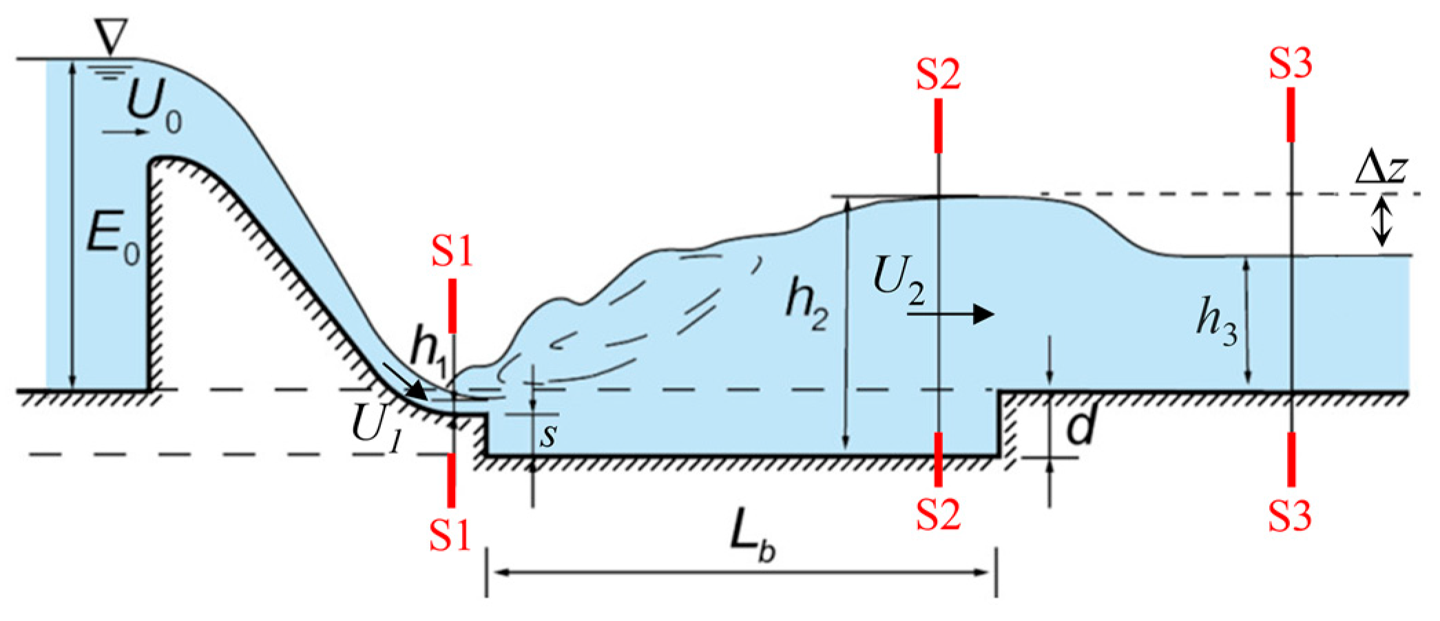
Estimate the negative step height (S).
The step height of a negative step stilling basin can be estimated based on the maximum allowable near-bottom flow velocity, as defined by specific engineering requirements [36], and is expressed as
s = 0.984 E 0 q U b 0 1.982 2
where U b 0 represents the maximum allowable near-bottom flow velocity. In the preliminary design, the U b 0 for the unreinforced stilling basin floor was 15 m/s in this case. Consequently, the calculated step height was s   = 8.75 m. However, according to the Design Specification Manual [36], an excessively large negative step height may induce undesirable flow patterns, such as surface flows, where water swirls and vortices form near the surface, often leading to insufficient energy dissipation. Therefore, considering both Equation (36) and the design manual, a step height of s   = 8.0 m was adopted for a more balanced design.
(2)
Determining the depth of the stilling basin (d).
The inflow depth ( h 1 ) can be calculated as follows:
E 0 + d s = h 1 + q 2 2 g χ 2 h 1 2
Here, E 0 is the energy head at the upstream section of the dam, given as E 0 = 140 m. χ is the flow velocity coefficient of the spillway.
In this case, χ = 0.88 was adopted. The depth of the stilling basin was initially assumed to be zero ( d = 0   m ). Based on Equation (37), the resulting value for h 1 was 2.88 m. Next, using the estimation of the sequent depth ratio for the critical A-jump, as described in Equation (16) and Equation (18), where the correction factor ( φ ) is 1.0 when the incident angle ( θ ) is zero, the sequent depth at section S2 was determined to be h 2 = 33.53   m . In this scenario, since d = 0 m and h 2 > h 3 , a critical A-jump cannot form. Instead, a minimum B-jump will occur. This minimum B-jump is characterized by an insufficient energy dissipation rate and the presence of unfavorable flow patterns. Therefore, the depth of the stilling basin cannot be zero and should be determined using the following equation:
d = σ j h 2 h 3 z
where σ j is the submergence factor, with σ j = 1.05 adopted in this case. z represents the water level drop at the outlet of the stilling basin, and is calculated as follows:
z = q 2 2 g [ 1 χ h 3 2 1   σ j h 2 2 ]
where χ is the flow velocity coefficient in the stilling basin, with χ = 0.95 adopted. By substituting the known variables ( E 0 = 140 m; s   = 8.0 m; q = 127.4 m2/s; h 3 = 33.05 m) and solving Equations (16), (18), (37)–(39) associatively, we obtained h 1 = 2.78 m, h 2 = 34.11 m, d = 2.57 m, and F r 1 = 8.77 .
(3)
Determining the length of the stilling basin (Lb).
The empirical formula [37] for the length of a classic hydraulic jump is expressed as follows:
L j = 10.8 h 1 ( F r 1 1 ) 0.93
As noted in [38], adopting a negative step significantly shortens the length of the hydraulic jump. Therefore, the length of the critical A-jump in a negative step stilling basin can be estimated as follows:
L b = ( 0.7 ~ 0.8 ) L j
For safety reasons, the shortening factor is conservatively estimated to be 0.8. Using this factor, the hydraulic jump length of the critical A-jump can be calculated, yielding a length of the negative stilling basin L b = 161.7 m (161.0 m is adopted in engineering).
(4)
Estimating the energy dissipation rate (ER).
Based on the configuration described above, as summarized in Table 3, the energy dissipation rate of the designed negative step stilling basin was estimated using Equation (23). The result was E R = 0.704 , indicating a high energy dissipation efficiency.
(5)
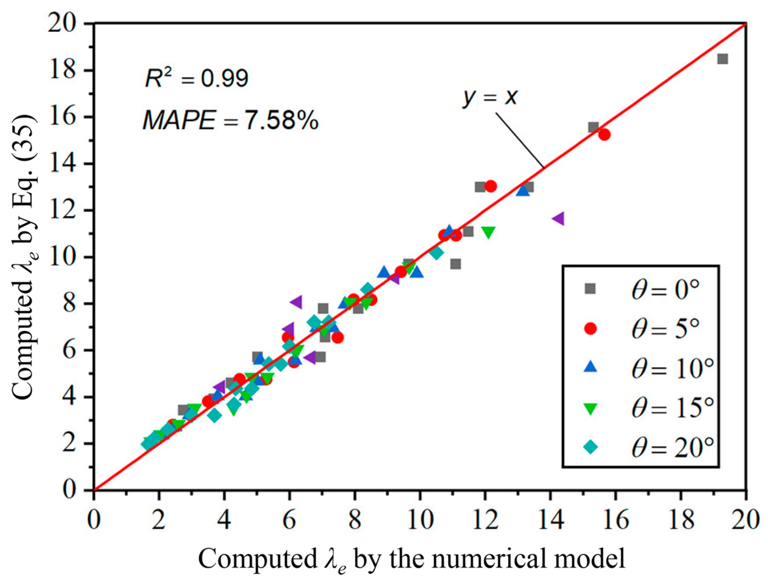
Estimating characteristic lengths of the generated critical A-jump.
The dimensionless roller length ( λ r ) and dimensionless reattachment length ( λ e ) could be estimated using Equations (29) and (35), respectively. Then, the results were λ r = 50.46 and λ e = 8.63 , with the corresponding roller length and reattachment length being L r = 140.3   m and L e = 24.0   m .

4.2. Validation

Up to this point, the main configuration of the characteristic parameters for the critical A-jump and those adopted for the stilling basin design have been established, as summarized in Table 3. To validate the reliability of the hydraulic parameter estimations for the critical A-jump proposed in this study, the hydraulic parameters calculated using the proposed formulas were compared with the results from numerical simulations. This comparison was undertaken to verify the effectiveness and applicability of the proposed estimations, as shown in Table 4. Overall, the proposed estimations for the key parameters of the critical A-jump aligned well with the numerical results, with an average relative error of −8.55%. The estimations for energy dissipation rate and reattachment length performed well, with relative errors all falling within acceptable limits ( ± 3.5 % ). Although the relative errors for the sequent depth ratio and roller length are relatively large, they remained below ± 20.0 % , which is considered acceptable for engineering applications.
Then, the performance of the designed negative step stilling basin was compared with that of the classical stilling basin, designed according to the Design Specification Manual [36] and computed using the numerical model, as shown in Table 5. Compared to the classical stilling basin, the negative step stilling basin featured a shorter basin length, while maintaining a comparable energy dissipation rate. However, the near-bottom flow velocity was significantly reduced, greatly improving the safety of the stilling basin floor. It should be noted that, although the bottom velocity was reduced to 26.6 m/s, it remained higher than the allowable maximum near-bottom flow velocity for the unreinforced stilling basin floor ( U b 0 = 15   m / s ) used in the design process. This indicates that the floor of the stilling basin should be reinforced in practice.
Figure 13 compares the flow patterns between the negative step stilling basin and the classical stilling basin. In Figure 13a, a significant A-jump occurs in the negative step stilling basin, with distinct jet, reattachment, and upper circulation regions. Additionally, the outflow is relatively stable. In contrast, Figure 13b shows that the jet in the classical stilling basin lacks a proper water cushion effect and directly impacts on the floor, resulting in a large near-bottom flow velocity that may damage the basin floor, up to 46.2 m/s. The outflow also fluctuates significantly, creating a wave-like surface, which indicates that engineering measures are needed downstream of the outflow to protect the surrounding structures.
In summary, the estimations proposed for the hydraulic characteristic parameters for critical A-jumps provided accurate predictions of key characteristics, offering valuable insights for guiding and optimizing the design of negative step stilling basins in practical engineering. The negative step stilling basin designed based on the specifications and the estimation methods proposed in this work demonstrated a high energy dissipation efficiency and ensured stable outflows, significantly outperforming the classical stilling basin.

5. Conclusions

Systematical investigations were conducted on the research of the hydraulic characteristics of A-jumps in negative step stilling basins, with a total number of 75 cases using a 2-D incompressible RANS numerical model. The influence of inflow conditions, including flow depth, velocity, discharge, and Froude number, as well as the stilling basin parameters, such as negative step height and incident angle, on the key hydraulic characteristics of A-jumps, specifically, the sequent depth ratio, roller length, reattachment length, and energy dissipation rate, were systematically studied. These studies provided potential contributions to suggest negative step stilling basin designs for engineering applications. The main conclusions are as follows:
(1)
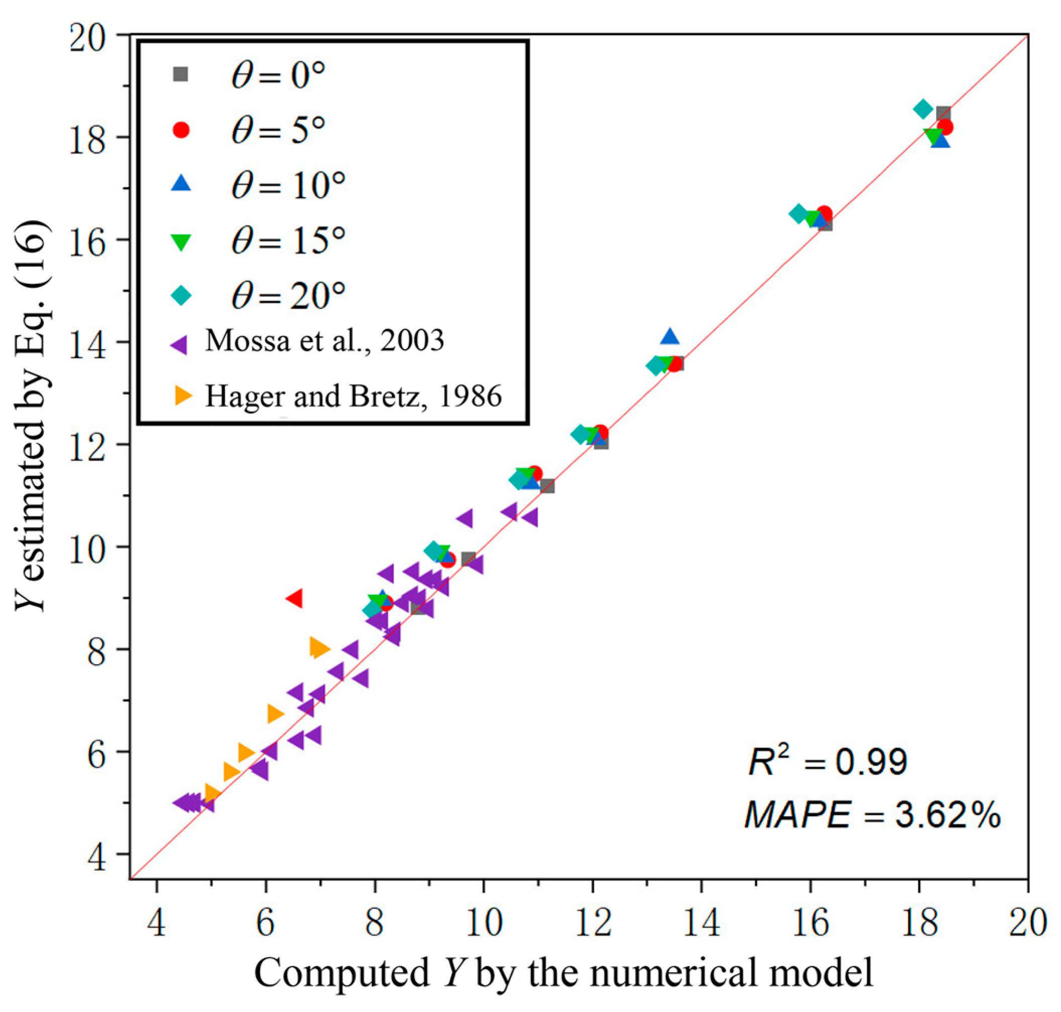
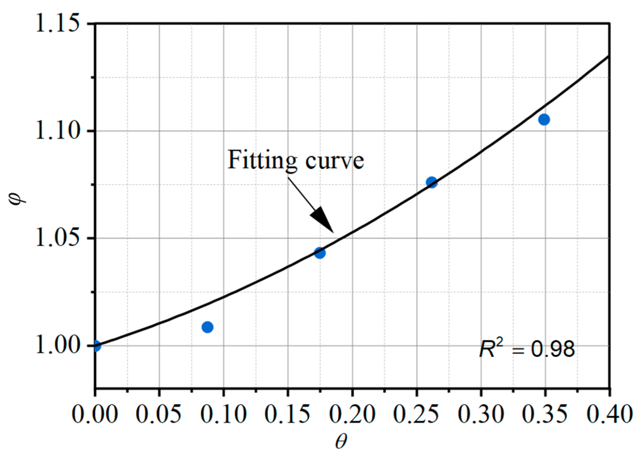
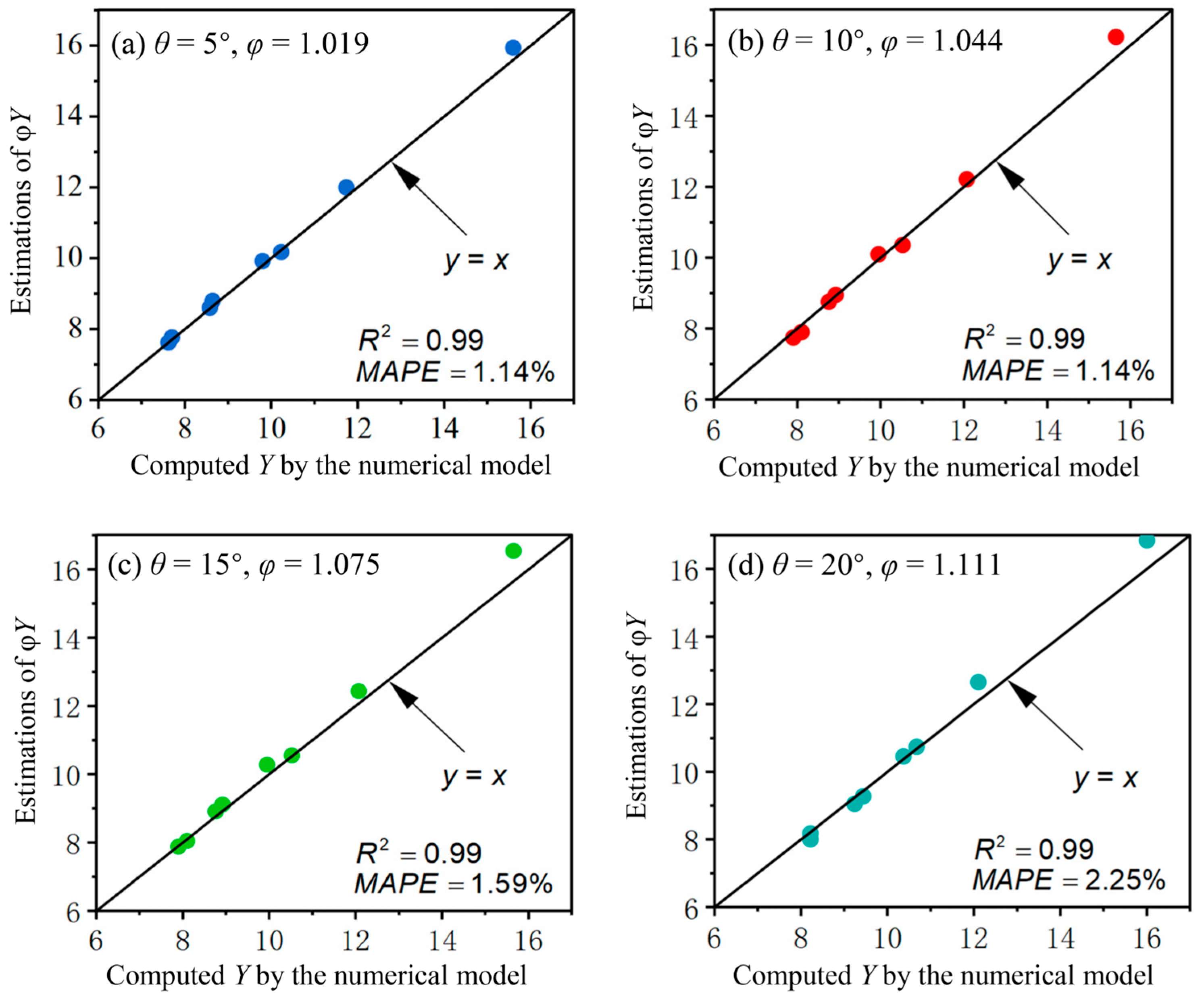
The relationship between the sequent depth ratio (Y) of the critical A-jumps and the inflow Froude (Fr1) number with the varying negative step height (S) and incident angle (θ) were derived based on the momentum equation. This formula was further revised by adding a correction coefficient (φ) to consider the significant influence of θ on Y when S stays at a low level with 0.833 ≤ S ≤ 2.5, based on the numerical results. The theoretical sequent depth ratio was first calculated using the following formula based on momentum conservation:
F r 1 2 = 1 2 ( Y 1 Y cos θ ) ( cos 2 θ   + S 2 Y 2 )
φ = 2.5 < S 10.0 1.0 0.833 S 2.50 0.371 θ 2 + 0.190 θ + 1.000
Then, the value was revised to φ Y , which provided an estimated sequent depth ratio for critical A-jumps, considering a wide range of negative step heights and the influence of the incident angle.
(2)
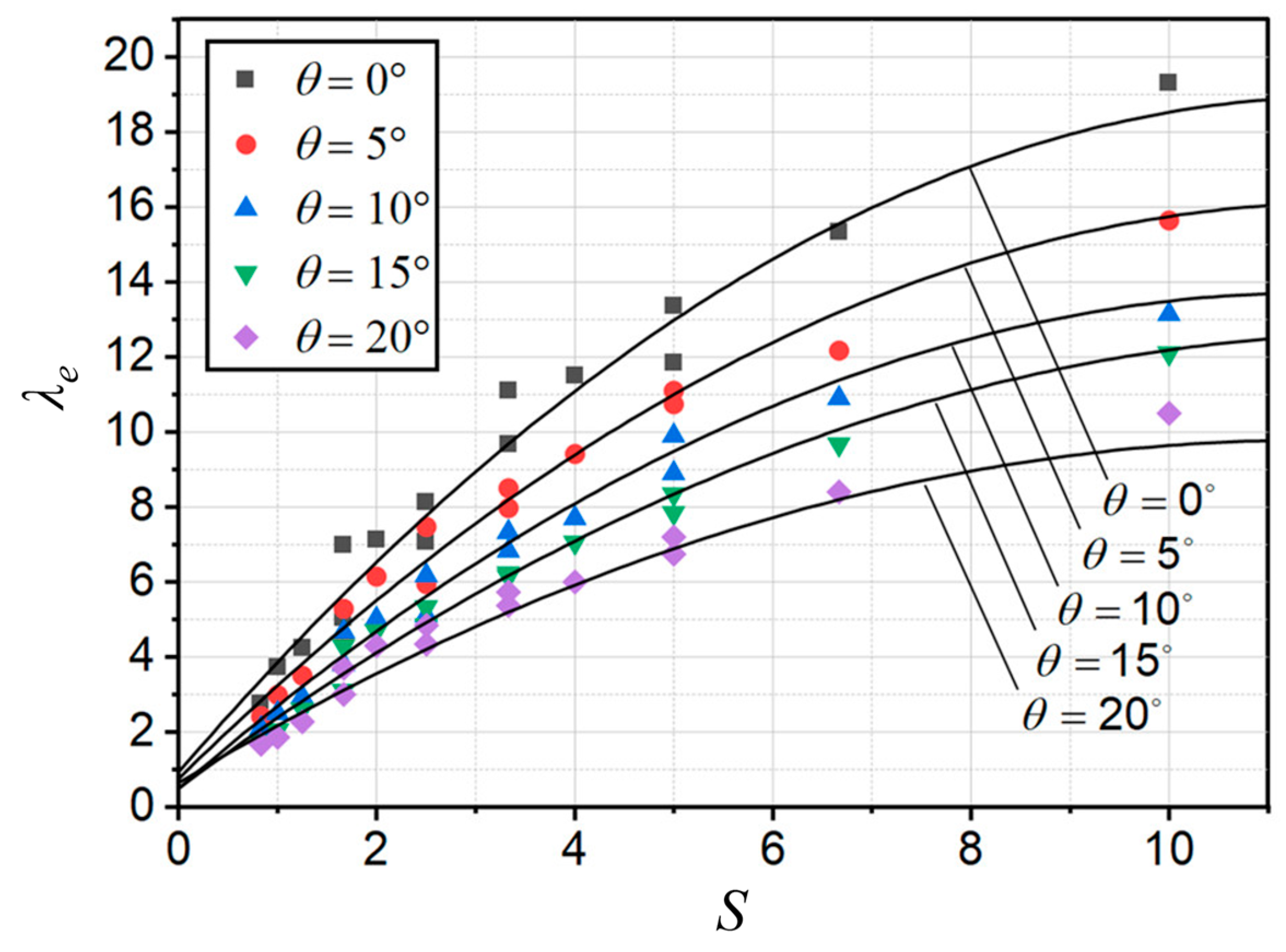
Based on the numerical results and regression analysis, an estimation for the dimensionless roller length was proposed, incorporating the influence of the incident angle. A reasonable roller length for A-jumps helps to control hydraulic jumps within the stilling basin, ensuring stable outflows and preventing undesirable flow patterns.
λ r = 15.81 θ   4.35 + [ 0.66 θ 2 + 0.58 θ + 5.39 ] S + 6 ( F r 1   1 ) 1 + ( 0.15 S ) 2
(3)
An estimation for the dimensionless reattachment length was proposed, as it plays a crucial role in protecting the basin floor. The estimations were presented as follows:
λ e = 0.10 θ 2 + 0.20 θ   0.13 S 2 + [ 2.54 θ 2     4.82 θ + 3.04 ] S + [ 8.64 θ 2   3.98 θ + 0.96 ]
(4)
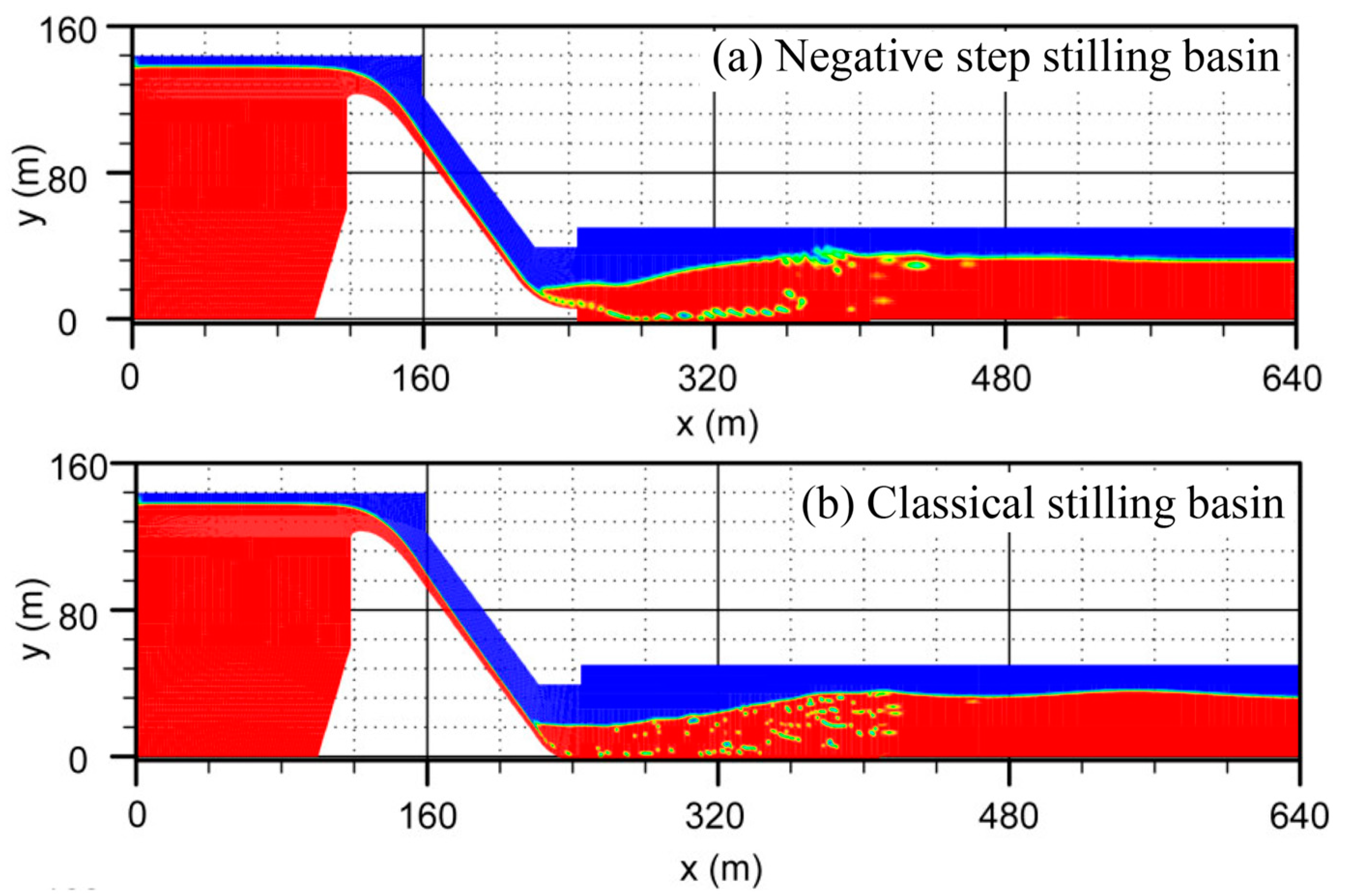
To validate the proposed estimations, a case study was conducted on a negative step stilling basin designed according to the Design Specification Manual and the proposed estimation methods. The results demonstrated that the estimated key hydraulic characteristics of A-jumps closely aligned with the numerical predictions. The designed stilling basin effectively enhanced the energy dissipation efficiency, stabilized outflows, and significantly reduced the near-bottom flow velocity, thereby preventing impact damage to the basin floor. Compared to the classical stilling basin, the proposed design achieved superior performance. This case study underscored the practical applicability and engineering significance of the proposed estimations.
(5)
Estimations of the key characteristic parameters for A-jumps were derived based on scenarios where the dimensionless step height (S = s/h1) ranged from 0.83 to 10.00, the incident angle (θ) varied between 0° and 20°, and the inflow Froude number (Fr1) spanned from 5.6 to 11.3. Although these ranges covered the parameter space of current high dam and large reservoir spillways as comprehensively as possible, the applicability and accuracy of the estimation method must be further verified if variables exceed this range.

Author Contributions

Methodology, L.J.; Validation, L.J. and Y.L.; Formal analysis, L.J., Y.D., Y.L., L.F. and X.G.; Data curation, L.J., Y.D. and L.F.; Writing—original draft, L.J.; Writing—review and editing, X.G. All authors have read and agreed to the published version of the manuscript.

Funding

This study was financially supported by the Yunnan Province Basic Research Program—General Program (202501CF070198).

Data Availability Statement

The original contributions presented in this study are included in the article. Further inquiries can be directed to the corresponding author.

Conflicts of Interest

Authors Lei Jiang, Yao Deng, Yangrong Liu and Lindong Fang are employed by the POWERCHINA Kunming Engineering Corporation Limited. The remaining authors declare that the research was conducted in the absence of any commercial or financial relationships that could be construed as a potential conflict of interest.

Appendix A

Parameters adopted in the numerical studies and corresponding computed results are summarized in Table A1.
Table A1. Summary of parameters adopted in numerical studies and corresponding computed results.
NO. s (cm) θ   ( ° )q (m2/s)h1 (m)U1 (m/s) F r 1 Y λ r λ e E R (%)
1500.1000.0205.00011.315.60 62.35 7.05 77.2
2500.1400.0304.6678.611.70 45.57 5.03 71.2
3500.1800.0404.5007.29.70 38.85 4.23 66.4
4500.2200.0504.4006.38.44 32.10 3.70 62.4
5500.2600.0604.3335.67.57 30.75 2.75 59
6550.1000.0205.00011.315.60 64.65 5.95 77.1
7550.1400.0304.6678.611.73 49.67 4.47 71
8550.1800.0404.5007.29.80 39.65 3.50 65.9
9550.2200.0504.4006.38.58 34.58 2.98 61.6
10550.2600.0604.3335.67.62 30.95 2.42 58.6
115100.1000.0205.00011.315.65 67.10 5.10 76.8
125100.1400.0304.6678.612.07 52.27 3.80 69.8
135100.1800.0404.5007.29.95 39.73 2.93 65
145100.2200.0504.4006.38.76 35.44 2.50 60.3
155100.2600.0604.3335.67.90 32.80 2.10 56.4
165150.1000.0205.00011.315.70 69.85 4.85 76.3
175150.1400.0304.6678.612.30 53.90 3.10 68.6
185150.1800.0404.5007.210.10 40.48 2.60 63.8
195150.2200.0504.4006.39.04 36.14 2.04 58.3
205150.2600.0604.3335.68.15 33.33 1.75 54.2
215200.1000.0205.00011.316.00 72.10 4.35 75.1
225200.1400.0304.6678.612.10 54.40 3.00 68.4
235200.1800.0404.5007.210.38 41.23 2.28 61.8
245200.2200.0504.4006.39.24 37.88 1.86 56.2
255200.2600.0604.3335.68.22 33.70 1.67 52.7
261000.1000.0205.00011.316.29 67.85 11.85 77
271000.1400.0304.6678.612.03 50.80 9.67 71.5
281000.1800.0404.5007.29.93 41.73 8.13 67
291000.2200.0504.4006.38.64 33.60 7.10 63.2
301000.2600.0604.3335.67.67 33.00 6.97 60.3
311050.1000.0205.00011.316.50 70.65 10.75 76.6
321050.1400.0304.6678.612.23 51.13 8.50 70.9
331050.1800.0404.5007.210.23 43.63 7.48 65.8
341050.2200.0504.4006.38.64 35.80 6.14 63
351050.2600.0604.3335.67.70 33.10 5.28 60
3610100.1000.0205.00011.316.35 70.80 9.90 76.6
3710100.140.0304.6678.612.10 52.60 7.33 70.9
3810100.1800.0404.5007.210.53 45.68 6.18 64.4
3910100.2200.0504.4006.38.92 39.80 5.02 61.4
4010100.2600.0604.3335.68.10 34.28 4.67 57.3
4110150.1000.0205.00011.316.45 71.10 8.35 76
4210150.1400.0304.6678.612.22 54.30 6.23 70.1
4310150.1800.0404.5007.210.70 45.80 5.33 63.2
4410150.2200.0504.4006.39.22 40.00 4.68 59.3
4510150.2600.0604.3335.68.17 34.37 4.28 56.2
4610200.1000.0205.00011.316.50 75.40 6.75 75.3
4710200.1400.0304.6678.612.20 60.03 5.37 69.4
4810200.1800.0404.5007.210.68 46.20 4.85 62.4
4910200.2200.0504.4006.39.44 43.40 4.30 57.3
5010200.2600.0604.3335.68.22 36.33 3.70 54.9
512000.1000.0205.00011.318.45 69.80 19.30 75.6
522000.1400.0304.6678.613.57 53.47 15.33 70.1
532000.1800.0404.5007.211.18 42.05 13.35 65.5
542000.2200.0504.4006.39.74 37.94 11.50 61.5
552000.2600.0604.3335.68.80 33.33 11.10 57.6
562050.1000.0205.00011.318.20 72.75 15.65 75.8
572050.1400.0304.6678.613.57 53.77 12.17 70
582050.1800.0404.5007.211.43 45.55 11.10 64.6
592050.2200.0504.4006.39.74 38.30 9.42 61.3
602050.2600.0604.3335.68.90 34.63 7.97 57
6120100.1000.0205.00011.317.90 74.65 13.15 76
6220100.1400.0304.6678.614.07 54.70 10.90 68.5
6320100.1800.0404.5007.211.23 45.73 8.90 64.9
6420100.2200.0504.4006.39.80 41.06 7.70 60.8
6520100.2600.0604.3335.68.95 36.67 6.83 56.4
6620150.1000.0205.00011.318.05 76.75 12.10 75.4
6720150.1400.0304.6678.613.60 54.77 9.67 69.1
6820150.1800.0404.5007.211.43 46.98 7.85 63.7
6920150.2200.0504.4006.39.92 41.50 7.06 59.6
7020150.2600.0604.3335.68.95 37.68 6.15 55.7
7120200.1000.0205.00011.318.55 76.85 10.50 74.1
7220200.1400.0304.6678.613.53 57.47 8.40 68.6
7320200.1800.0404.5007.211.30 47.30 7.20 63.3
7420200.2200.0504.4006.39.92 44.50 6.00 58.8
7520200.2600.0604.3335.68.75 38.82 5.73 55.9

References

  1. Luo, M.; Wang, H.; Zheng, X.; Wüthrich, D.; Bai, R.; Liu, S. Air Entrainment and Free-Surface Fluctuations in A-Type Hydraulic Jumps with an Abrupt Drop. J. Hydraul. Res. 2023, 61, 720–734. [Google Scholar]
  2. Jiang, L.; Diao, M.; Wang, C. Investigation of a Negative Step Effect on Stilling Basin by Using CFD. Entropy 2022, 24, 1523. [Google Scholar] [CrossRef] [PubMed]
  3. Yang, J.; Teng, P.; Xie, Q.; Li, S. Understanding Water Flows and Air Venting Features of Spillway—A Case Study. Water 2020, 12, 2106. [Google Scholar] [CrossRef]
  4. Li, S.; Yang, J.; Ma, X.; Li, X. Flow Features in a Pooled Fishway with V-Shaped Weir Formation. Eng. Appl. Comput. Fluid Mech. 2020, 14, 1337–1350. [Google Scholar] [CrossRef]
  5. Wang, T.; Guo, X.; Guo, G.; Fu, H.; Yang, K. New Energy Dissipation Structures for Storm Discharge in Coastal Cities. In Proceedings of the International Conference on Hydraulics, Berlin, Germany, 2–4 November 2015. [Google Scholar]
  6. Yin, F.; Zhang, Y.; Nie, S.; Ji, H.; Ma, Z. A system-level CFD simulation model for investigating the energy dissipation mechanism of seawater pump and rotary energy recovery device in SWRO desalination system. Desalination 2024, 587, 117947. [Google Scholar]
  7. Grace, J.L.; Pickering, G.A. Evaluation of Three Energy Dissipators for Storm-Drain Outlets: Hydraulic Laboratory Investigation. J. Hydraul. Res. 1971, 9, 37–42. [Google Scholar]
  8. Hager, W.H.; Bretz, M. Hydraulic Jumps at Positive and Negative Steps. J. Hydraul. Res. 1986, 24, 237–253. [Google Scholar]
  9. Wang, H.; Ni, C.; Lyu, W.; Tang, L. A-Type Hydraulic Jumps Over a Negative Step: Numerical Investigation Based on Composite Modeling and Validation. Phys. Fluids 2023, 35, 105–121. [Google Scholar]
  10. Ohtsu, I.; Yasuda, H. Transition from Supercritical to Subcritical Flow at an Abrupt Drop. J. Hydraul. Res. 1991, 29, 309–328. [Google Scholar]
  11. Retsinis, E.; Papanicolaou, P. Supercritical Flow over a Submerged Vertical Negative Step. Hydrology 2022, 9, 74. [Google Scholar] [CrossRef]
  12. Quraishi, A.A.; Al-Brahim, A.M. Hydraulic Jump in Sloping Channel with Positive or Negative Step. J. Hydraul. Res. 1992, 30, 769–782. [Google Scholar] [CrossRef]
  13. Eroğlu, N.; Taştan, K. Local Energy Losses for Wave-Type Flows at Abrupt Bottom Changes. J. Irrig. Drain. Eng. 2020, 146, 04020029. [Google Scholar] [CrossRef]
  14. Bai, R.; Wang, H.; Tang, R.; Liu, S.; Xu, W. Roller Characteristics of Preaerated High-Froude-Number Hydraulic Jumps. J. Hydraul. Eng. 2021, 147, 04021008. [Google Scholar] [CrossRef]
  15. Negm, A.A.M. Hydraulic Jumps at Positive and Negative Steps on Sloping Floors. J. Hydraul. Res. 1996, 34, 409–420. [Google Scholar] [CrossRef]
  16. Mossa, J.; Petrillo, A.; Chanson, H. Tailwater Level Effects on Flow Conditions at an Abrupt Drop. J. Hydraul. Res. 2003, 40, 13. [Google Scholar] [CrossRef]
  17. Nasr Esfahani, M.J.; Shafai Bajestan, M. Dynamic Force Measurement of Roughened Bed B-Jump at an Abrupt Drop. Arch. Sci. J. 2012, 65, 47–54. [Google Scholar]
  18. Nyantekyi-Kwakye, B.; Clark, S.P.; Tachie, M.F.; Malenchak, J.; Muluye, G. Flow Characteristics within the Recirculation Region of Three-Dimensional Turbulent Offset Jet. J. Hydraul. Res. 2015, 53, 230–242. [Google Scholar] [CrossRef]
  19. Bayón-Barrachina, A.; Valero, E.; García-Bartual, R.; Vallés-Morán, F.; López-Jiménez, P. Performance Assessment of OpenFOAM and FLOW-3D in the Numerical Modeling of a Low Reynolds Number Hydraulic Jump. Environ. Model. Softw. 2016, 80, 322–335. [Google Scholar] [CrossRef]
  20. Helal, A.; Elshenawy, Y. Numerical Assessment of the Performance of Bed Water Jets in Submerged Hydraulic Jumps. J. Irrig. Drain. Eng. 2020, 146, 04020014. [Google Scholar] [CrossRef]
  21. Macián-Pérez, J.F.; Bayón, A.; García-Bartual, R.; López-Jiménez, P.A.; Vallés-Morán, F.J. Characterization of Structural Properties in High Reynolds Hydraulic Jump Based on CFD and Physical Modeling Approaches. J. Hydraul. Eng. 2020, 146, 04020079. [Google Scholar] [CrossRef]
  22. Huang, G.; Diao, M.; Jiang, L.; Wang, C.; Jia, W. Experimental Study on Wave Characteristics of Stilling Basin with a Negative Step. Entropy 2022, 24, 445. [Google Scholar] [CrossRef] [PubMed]
  23. Kirkgoz, M.S.; Akoz, M.S.; Oner, A.A. Numerical Modeling of Flow over a Chute Spillway. J. Hydraul. Res. 2009, 47, 790–797. [Google Scholar] [CrossRef]
  24. Akoz, M.S.; Gumus, V.; Kirkgoz, M.S. Numerical Simulation of Flow over a Semicylinder Weir. J. Irrig. Drain. Eng. 2014, 140, 04014016. [Google Scholar] [CrossRef]
  25. Bayón-Barrachina, A.; López-Jiménez, P.A. Numerical Analysis of Hydraulic Jumps Using OpenFOAM. J. Hydroinform. 2015, 17, 662–678. [Google Scholar] [CrossRef]
  26. Spalding, B.E.; Launderd, B. The Numerical Computation of Turbulent Flows. Comput. Methods Appl. Mech. Eng. 1974, 3, 269–289. [Google Scholar]
  27. Yakhot, V.; Orszag, S.A. Renormalization Group Analysis of Turbulence. I. Basic Theory. J. Sci. Comput. 1986, 1, 3–51. [Google Scholar]
  28. Koutsourakis, N.; Bartzis, J.G.; Markatos, N.C. Evaluation of Reynolds Stress, k-ε, and RNG k-ε Turbulence Models in Street Canyon Flows Using Various Experimental Datasets. Environ. Fluid Mech. 2012, 12, 379–403. [Google Scholar] [CrossRef]
  29. Hirt, C.W.; Nichols, B.D. Volume of Fluid (VOF) Method for the Dynamics of Free Boundaries. J. Comput. Phys. 1981, 39, 201–225. [Google Scholar]
  30. Simsek, O.; Soydan, N.G.; Gümü, V.; Akz, M.S.; Kirkgz, M.S. Numerical Modeling of B-Type Hydraulic Jump at an Abrupt Drop. Tek. Dergi 2015, 26, 7215–7240. [Google Scholar]
  31. Issa, R.I. Solution of the Implicitly Discretised Fluid Flow Equations by Operator-Splitting. J. Comput. Phys. 1986, 62, 40–65. [Google Scholar]
  32. Hager, W.H. B-Jumps at Abrupt Channel Drops. J. Hydraul. Eng. 1985, 111, 861–866. [Google Scholar]
  33. Hager, W.H.; Sinniger, R. Flow characteristics of the hydraulic jump in a stilling basin with an abrupt bottom rise. J. Hydraul. Res. 1985, 23, 101–113. [Google Scholar]
  34. Hager, W.H.; Bremen, L.; Kawagoshi, N. Classical Hydraulic Jump: Length of Roller. J. Hydraul. Res. 1990, 28, 591–608. [Google Scholar]
  35. Guan, X.; Hu, K.; Chen, X.; Gao, J.; Shi, H. Investigating the intense sediment load by dam-break floods using a meshless two-phase mathematical model. Water Resour. Res. 2024, 60, e2023WR035399. [Google Scholar]
  36. National Energy Administration. Design Guidelines for Energy Dissipation and Scour Prevention of Hydraulic Structures in Hydropower Projects; China Electric Power Press: Beijing, China, 2019.
  37. Li, W. Hydraulic Calculation Manual; China Water Power Press: Beijing, China, 2006. (In Chinese) [Google Scholar]
  38. Sichuan University Key Laboratory of Hydraulics and Mountain River Development & Protection. Hydraulics; Higher Education Press: Beijing, China, 2016; Volume, I. (In Chinese) [Google Scholar]
Figure 1. Schematic of energy dissipation through hydraulic jumps.
Water 17 00960 g001
Figure 2. Sketchup of the critical A-jump in a negative step stilling basin.
Water 17 00960 g002
Figure 3. Sketchup of the computational domain and boundary conditions.
Water 17 00960 g003
Figure 4. Comparisons of the observed and computed (Mesh1) water surface elevations.
Water 17 00960 g004
Figure 5. Relationships between the sequent depth ratio ( Y ) and inflow Froude number ( F r 1 ) of critical A-jumps with different incident angles ( θ ) and dimensionless step heights ( S ). Note that CHJ represents the relationship from a classical hydraulic jump, which commonly occurs in flat-bottomed stilling basins with a relatively lower energy dissipation rate.
Water 17 00960 g005
Figure 6. Comparison of the sequent depth ratio Y computed by the numerical model and that obtained by Equation (16). Note that the data pertain to the specific range of dimensionless step heights between 2.5 and 10.0 ( 2.5 < S 10.0 ) [8,16].
Water 17 00960 g006
Figure 7. Relationship between the incident angle ( θ ) and the correction factor ( φ ).
Water 17 00960 g007
Figure 8. Comparison of the revised sequent depth ratio ( φ Y ) estimated using Equations (16) and (18), incorporating corrections for θ , with numerical model results. The data correspond to dimensionless step heights in the range 0.833 S 2.5 .
Water 17 00960 g008
Figure 9. Comparison of dimensionless roller lengths estimated by Equation (29) and those computed using the numerical model [8].
Water 17 00960 g009
Figure 10. Relationship between the dimensionless step height ( S ) and reattachment length ( λ e ), along with the corresponding fitting curves.
Water 17 00960 g010
Figure 11. Comparison of the numerical results with the reattachment lengths estimated by Equation (35).
Water 17 00960 g011
Figure 12. Schematic diagram of the negative step stilling basin design case.
Water 17 00960 g012
Figure 13. Comparisons of the flow patterns between the (a) negative step stilling basin and (b) classical stilling basin.
Water 17 00960 g013
Table 2. Relative errors of the computed water surface elevations for different grid schemes. Note that η represents the water surface elevation at specific locations.
x (m) η 1 (m) η 2 (m) η 3 (m) η exp (m) RE 1 RE 2 RE 3
0.1000.1000.0970.0960.103−2.91%−5.83%−6.80%
0.1140.0970.0950.0960.098−1.02%−3.06%−2.04%
0.1450.0890.0870.0850.0881.14%−1.14%−3.41%
0.1650.0750.0740.0740.076−1.32%−2.63%−2.63%
0.1960.0910.0940.0950.0883.41%6.82%7.95%
0.2170.0910.0920.0950.0892.25%3.37%6.74%
0.2650.0910.0950.0960.091.11%5.56%6.67%
0.3160.0930.0950.0960.0921.09%3.26%4.35%
0.3640.0950.0950.0960.0923.26%3.26%4.35%
0.4660.0950.0950.0960.0932.15%2.15%3.23%
0.5660.0950.0950.0960.0950.00%0.00%1.05%
Table 3. Summary of key parameters for the designed negative stilling basin.
ParametersEstimationsEstimated ValueAdopted Value
Negative   step   height   of   ( s )Equation (36)8.75 m8.0 m
Depth   of   the   stilling   basin   ( d )Equations (16), (18), (37)–(39)2.57 m2.57 m
Inflow depth ( h 1 )Equations (16), (18), (37)–(39)2.78 m2.78 m
Sequent depth ( h 2 )Equations (16), (18), (37)–(39)34.11 m34.11 m
Length   of   the   stilling   basin   ( L b )Equations (40) and (41)161.7 m161.0 m
Energy   dissipation   rate   ( E R )Equation (23)70.4%-
Dimensionless   roller   length   ( λ r )Equation (29)50.46-
Dimensionless   reattachment   length   ( λ e )Equation (35)8.63-
Table 4. Comparisons of hydraulic parameters estimated by the proposed formula and numerical results.
Values Y E R (%) L r (m) L e (m)
Estimated by the proposed formula12.370.4140.324.0
Computed by the numerical model14.672.5173.223.2
Relative error−15.75%−2.90%−19.00%3.45%
Table 5. Comparisons of the designed negative step stilling basin with the classical stilling basin (numerical results).
Type s (m) d (m)Lb (m) E R (%) u b m a x (m/s) L r (m) L e (m)
Negative step stilling basin8.02.57161.072.526.6173.223.2
Classical stilling basin0.02.09164.073.246.2187.9-
Disclaimer/Publisher’s Note: The statements, opinions and data contained in all publications are solely those of the individual author(s) and contributor(s) and not of MDPI and/or the editor(s). MDPI and/or the editor(s) disclaim responsibility for any injury to people or property resulting from any ideas, methods, instructions or products referred to in the content.

