Article

Numerical Simulation of the Hydrodynamic Behavior of Immersed Tunnel in Waves

1
China Ship Wind Power Clean Energy Technology (Beijing) Co., Ltd., Beijing 100089, China
2
PowerChina Huadong Engineering Corporation Limited, Hangzhou 311122, China
3
State Key Laboratory of Coastal and Offshore Engineering, Dalian University of Technology, Dalian 116024, China
*
Author to whom correspondence should be addressed.
Water 2025, 17(7), 1094; https://doi.org/10.3390/w17071094
Submission received: 13 February 2025 / Revised: 2 April 2025 / Accepted: 3 April 2025 / Published: 6 April 2025
(This article belongs to the Section Hydraulics and Hydrodynamics)

Abstract

:
The hydrodynamic response of immersed tunnel in waves is important for the design of immersed tunnel. The numerical wave tank that considers the coupling of wave field and floating body motion is established based on the OpenFOAM. The overset mesh method is adopted to refresh the meshes around the immersed tunnel in waves. In addition, the experimental data of floating body motion and wave force is applied to validate the numerical model. The hydrodynamic characteristics of the immersed tunnel under wave loads are numerically studied, focusing on the motion response and the force of the immersed tunnel. The results show that with the increase in wave height, the roll of the immersed tunnel increases, the amplitude of the horizontal force increases significantly, the amplitude of the vertical force remains basically unchanged, and the nonlinear enhancement of the roll motion response is observed. When the wave period is close to the natural period of the floating body, the roll angle reaches its maximum. Under irregular wave conditions, with the increase in significant wave height, the average amplitude of the immersed tunnel’s roll motion increases, which is significantly greater (about 2–3 times) than that under regular wave conditions. With the increasing average amplitude of horizontal force, the change in vertical force is not significant.

1. Introduction

As one of the most common forms of cross-sea transportation, the immersed tunnel has several advantages: minimal impact on the natural sea landscape, low noise pollution to the surrounding environment during operation, lower requirements for geological conditions and load-bearing capacity of the foundation, and multi-functional use, making it convenient to arrange municipal pipelines. With the gradual development of social economy and offshore construction technology, underwater tunnels have become a hot topic in modern transportation construction.
Immersed tunnels, due to their significant advantages, have been widely used globally and have continuously been the subject of research and development in practical engineering applications. Chen et al., Peng et al., Wu et al. [1,2,3] conducted hydrodynamic studies on the floating and sinking stages of tunnel segments for the Hong Kong-Zhuhai-Macao Bridge immersed tunnel, analyzing the motion response and force status of the tunnel under different combinations of wind, wave, and current loads. Cozijn et al. [4] studied the motion of tunnel segments during the sinking process under different wave loads, including changes in the forces on control cables and mooring lines. Partha et al. [5] used ModelSim software to simulate the sinking process of immersed tunnels and compared the results with physical model tests to validate their accuracy. Jensen et al. [6] studied the motion response of tunnel segments during the sinking process under offshore wave loads. Hakkaart [7] researched the impact of wave loads on tunnel segments during the floating process in the Boston Immersed Tunnel project. Gong et al. [8] investigated the wave loads on two adjacent boxes with different sizes using OpenFOAM. Aono et al. [9] studied the stability of tunnel segments that were already sunk to the trench under different wave loads in the Naha Immersed Tunnel project in Japan, conducting numerical simulations and experiments to calculate the wave loads on tunnel segments, focusing on the influence of wave factors, ballast weight, and the bottom friction coefficient of the tunnel segments on sliding stability.
Due to the complex and variable marine environment in which the immersed tunnel is located, the key construction processes such as floating, sinking, and docking are susceptible to marine dynamic loads from wind, waves, currents, and tides, leading to unstable motion states. Consequently, many scholars both domestically and internationally have conducted research on the motion response and force status of immersed tunnels under wave action. Kasper et al. [10] studied the impact of different wave conditions on the stability of tunnel segments during the sinking process, focusing on the influence of offshore deep-water wave loads. Wu et al. [11] applied three-dimensional potential flow theory, using a combination of Matlab, Fortran, and Ansys, to investigate the nonlinear wave loads experienced by large-scale immersed tunnel segments during floating under irregular waves. This study compared the results with experimental data and analyzed the effects of wave heights and wave periods on the wave forces and motion of the segments.
In this study, a two-dimensional numerical wave tank capable of generating both regular and irregular waves was established based on the open-source code OpenFOAM 1712. The overset mesh method is adopted to simulate the coupling of the flow field and the immersed tunnel, and it can accurately simulate the interaction between immersed tunnel and waves. By comparing the numerical results with existing experimental data, the accuracy of this numerical model in simulating the motion response of floating bodies and the wave forces on structures was validated. After that, the effects of wave height and wave period on the roll motion response and forces of the immersed tunnel are discussed, which is beneficial for the engineering design. The comparison of hydrodynamic response of the immersed tunnel between regular waves and irregular waves is also discussed, and it is useful for the stability analysis of immersed tunnels in complex sea conditions.

2. Numerical Model

In the waiting stage before sinking, the immersed tunnel is considered a complex, single floating structure. In this study, the motion of the immersed tunnel in waves is simulated using the overset mesh method. The governing equations for the fluid are solved using the finite volume method (FVM), and the PISO (Pressure-Implicit with Splitting of Operators) algorithm is used to solve the velocity-pressure coupling problem.

2.1. Governing Equations

The flow of incompressible viscous fluids follows the principles of momentum conservation and mass conservation. The Navier–Stokes equations are selected in this study to describe the fluid flow around the immersed tunnel under wave action. The governing equations are expressed in tensor form as follows:
Continuity equation
ρ t + ( ρ U i ) x i = 0
Momentum equation
( ρ U i ) t + ( ρ U i U j ) x i = P t + ρ g i + x j ( μ + μ t ) ( U i x j + U j x i )
In the equations, t represents time, ρ is fluid density, P = p + (2/3)ρk, k is turbulent kinetic energy, Ui and Uj are the time-averaged velocity components (i and j = 1, 2, 3), gi is the gravitational acceleration, μ and μt represent the fluid’s viscosity and turbulent viscosity coefficients, respectively. The two transport equations solved by the SST k-ω turbulence model are the k equation and the ω equation, which are as follows:
( ρ k ) t + ( ρ U i k ) x i = P k ~ β * ρ k ω + x i ( μ + σ k μ t ) k x i ,
( ρ ω ) t + ( ρ U i ω ) x i = α ρ S 2 + x j ( μ + σ k μ t ) ω x i + 2 ( 1 F 1 ) ρ σ ω 2 1 ω k x i ω x i ,
In the equations, k is the turbulent kinetic energy, ω is the turbulent dissipation rate, β * is a model constant, and σ k is the turbulent Prandtl number for k. P k ~ is a limiter used to avoid the formation of turbulence in the stagnation region; Fi is a mixed function.
In order to accurately capture the free surface during numerical calculations, the Volume of Fluid (VOF) method is used to track the free surface. The VOF method solves the transport equation for the phase function α to represent the specific position of the free surface. The phase function α is defined as follows:
α = 0 0 < α < 0 α = 1
When α = 1 , the cell is fully occupied by water; when α = 0 , the cell is fully occupied by air. When 0 < α < 1 , the cell is at the free surface, containing both air and water. The density and viscosity of the mixed fluid are defined as follows:
ρ = α ρ w + ( 1 α ) ρ α μ = α μ w + ( 1 α ) μ α
where ρ w and μ w are the density and dynamic viscosity of water, ρ α and μ α are the density and dynamic viscosity of the air.

2.2. Floating Body Motion Equation

According to Newton’s second law, the three translational equations of motion of floating body are given as follows:
x ¨ G = 1 m G F x , y ¨ G = 1 m G F y , z ¨ G = 1 m G F z
where Fx, Fy and Fz are the components of the external forces along axes x, y and z, mG is the mass of floating body; x ¨ G , y ¨ G , z ¨ G are the acceleration of the mass center of the floating body.
Axes 1, 2, 3 are principal axes with origin at the center of the mass G, and thus the Euler equations of motion of a rigid body (Bhatt and Dukkipati [12]) are applied. In the body-coordinate system, the three rotational equations of motion of floating body are given by the following:
I 1 w 1 t + ( I 3 I 2 ) w 3 w 2 = M 1 , I 2 w 2 t + ( I 1 I 3 ) w 1 w 3 = M 2 I 3 w 3 t + ( I 2 I 1 ) w 1 w 2 = M 3
where subscripts 1, 2, 3 represent the body-coordinate axes 1, 2, 3; I1, I2, and I3 are the components of the moments of inertia I along the three principal axes; w1, w2, and w3 are the components of angular velocity vector along the three principal axes; M1, M2, and M3 are the components of the moment vector M along the three principal axes.

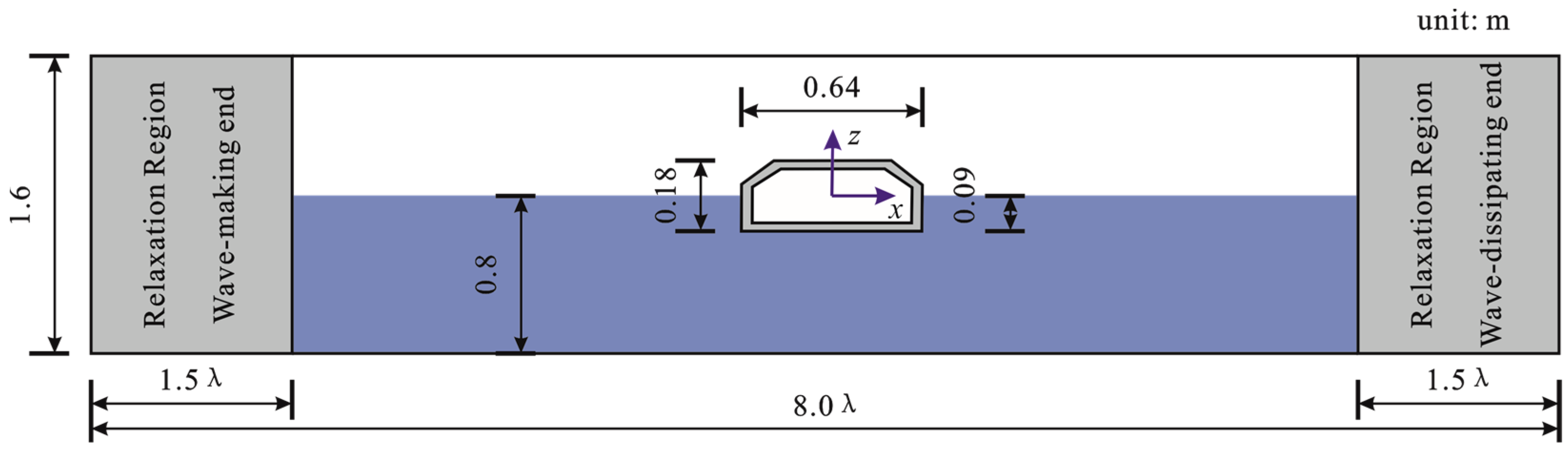
2.3. Wave Generation and Absorption

The numerical wave tank has a length of 8 times the wavelength and a height of 1.6 m, with a water depth of 0.8 m. The immersed tunnel floating body model is positioned at the center of the wave tank, and its dimensions are shown in Figure 1. The wave generation boundary is set on the left side, with relaxation zones at both ends to eliminate wave reflection. The length of the relaxation zones at both ends is set to 1.5 times the wavelength. Regular waves are generated using Stokes first-order wave theory, while irregular waves use the JONSWAP spectrum given by Goda [13]. The Froude similarity criterion can be used to handle the physical quantities’ proportional relationships between the prototype data and the calculated results.
The irregular waves are generated using the random phase method, as described by Charkrabarti [14], which, in the time domain, is the superposition of multiple regular waves.
η ( x , t ) = j = 1 n A j cos ( K j x 2 π f j t + ε j )
where A j is given by
A j = 2 S ( f j ) Δ f
where A j and K j are the wave amplitude and number of the individual wave components, respectively. ε j is the uniform distributive random phase between 0 and 2π.

3. Experimental Validation

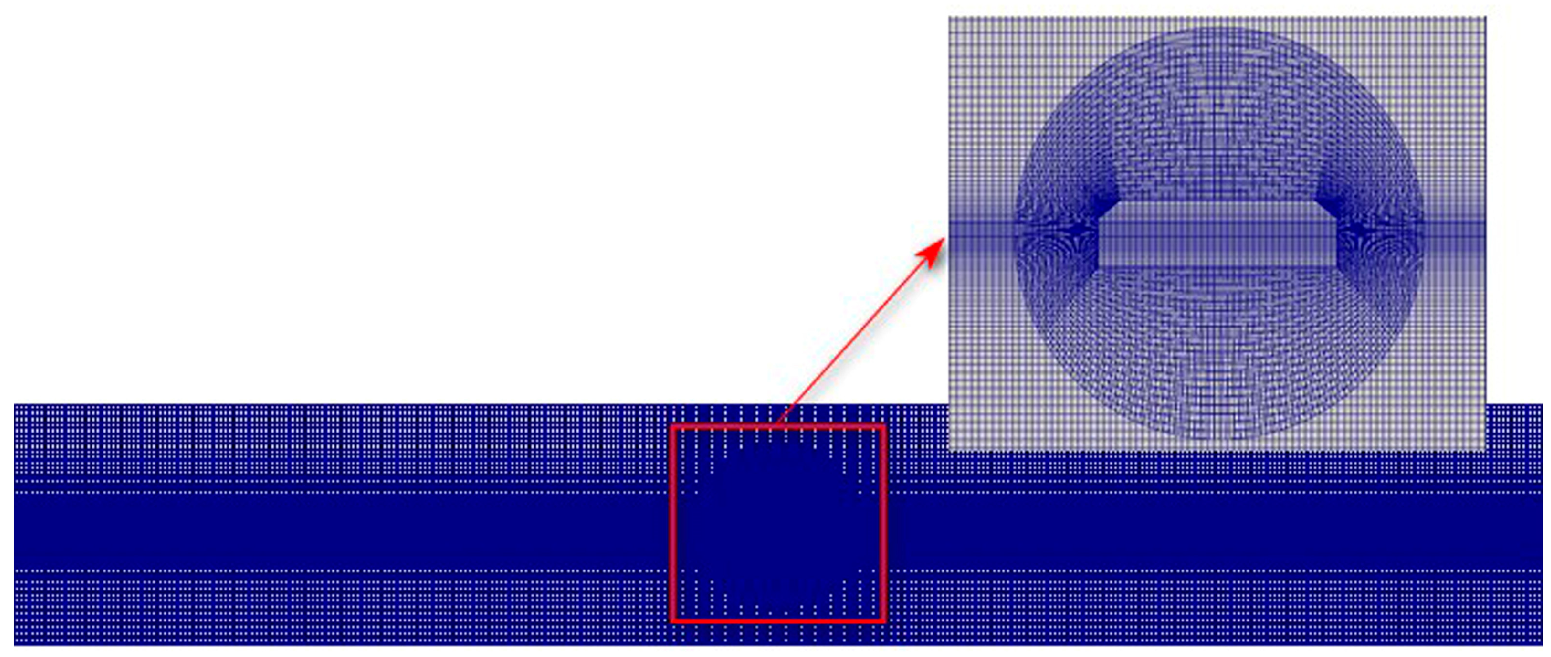
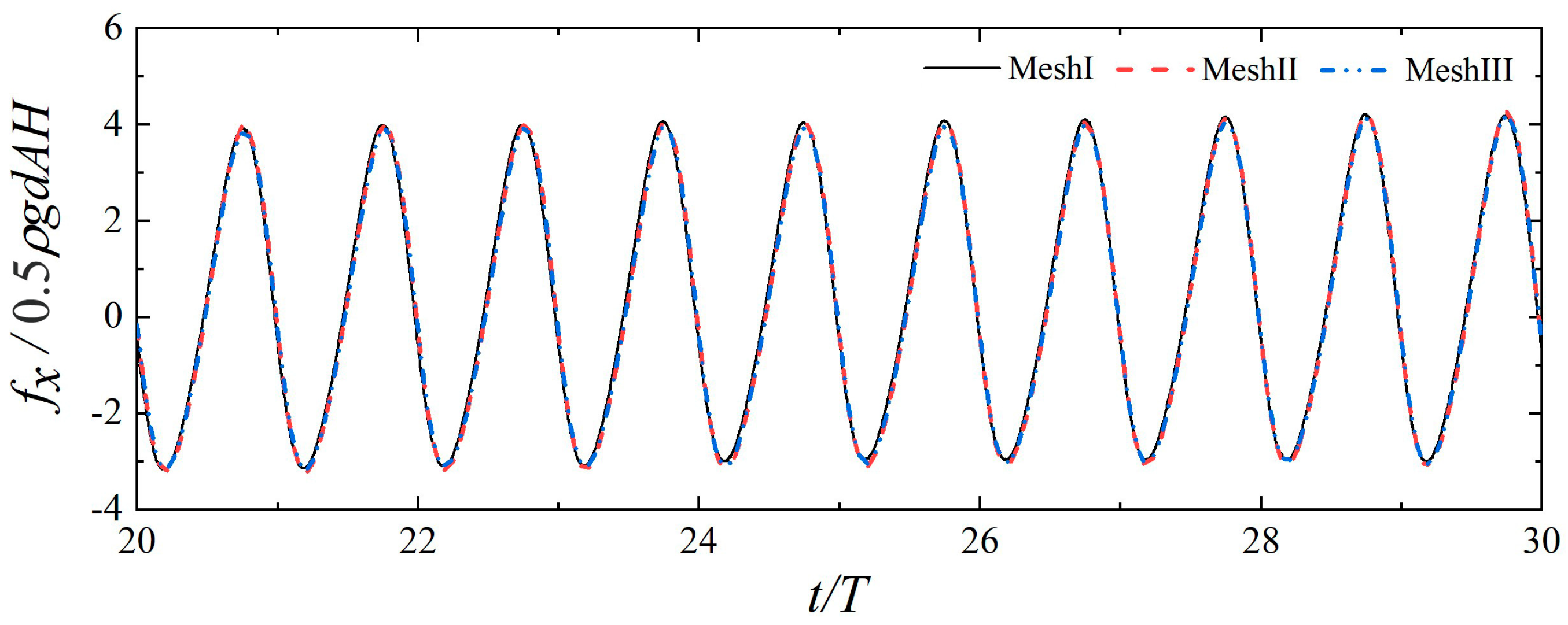
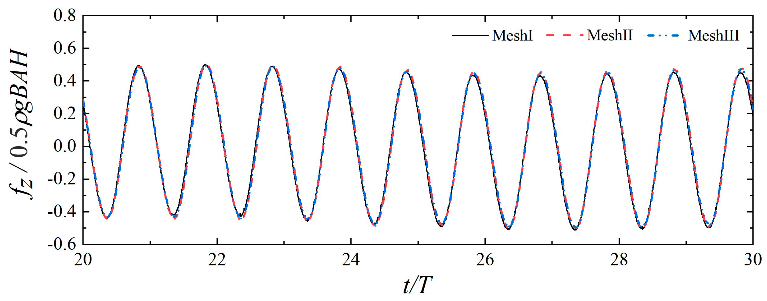
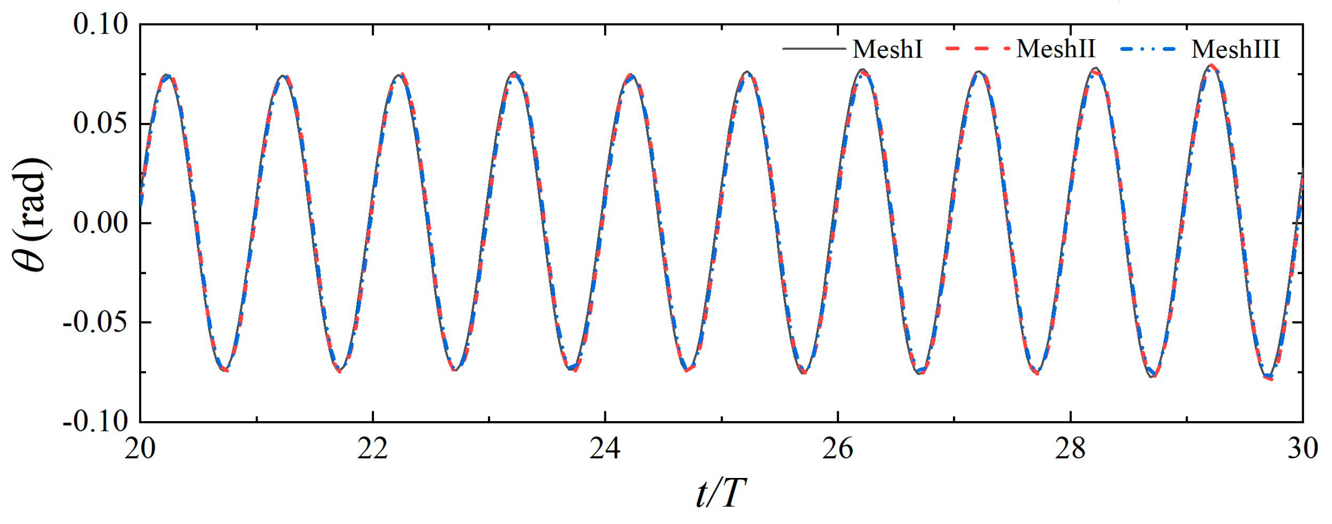
3.1. Mesh Convergence Analysis

Mesh convergence analysis is crucial for numerical simulations to ensure the accuracy of the computational results and improve computational efficiency. The mesh division schematic is shown in Figure 2. In this study, since the motion response and forces on the floating body are the main focus, the mesh near the free surface and structure surface is refined to ensure the accuracy of the simulation results.
A working condition with a wave height of H = 0.06 m and a wave period of T = 1.6 s was selected for mesh convergence analysis. Three kinds of mesh densities were used for calculations, and the details of the mesh division are shown in Table 1. Here, λ represents the wavelength, and H is the wave height. Figure 3, Figure 4 and Figure 5, respectively, show the numerical results of the horizontal force, vertical force, and roll motion of the floating body for the three kinds of mesh densities. The results indicate that the three kinds of mesh densities have little influence on the computational results, particularly Mesh II and Mesh III, which show that when one wavelength is divided into 80 meshes and one wave height into 18 meshes, the calculation accuracy can be satisfied. Therefore, in the subsequent research conditions, the mesh settings will use Mesh II.

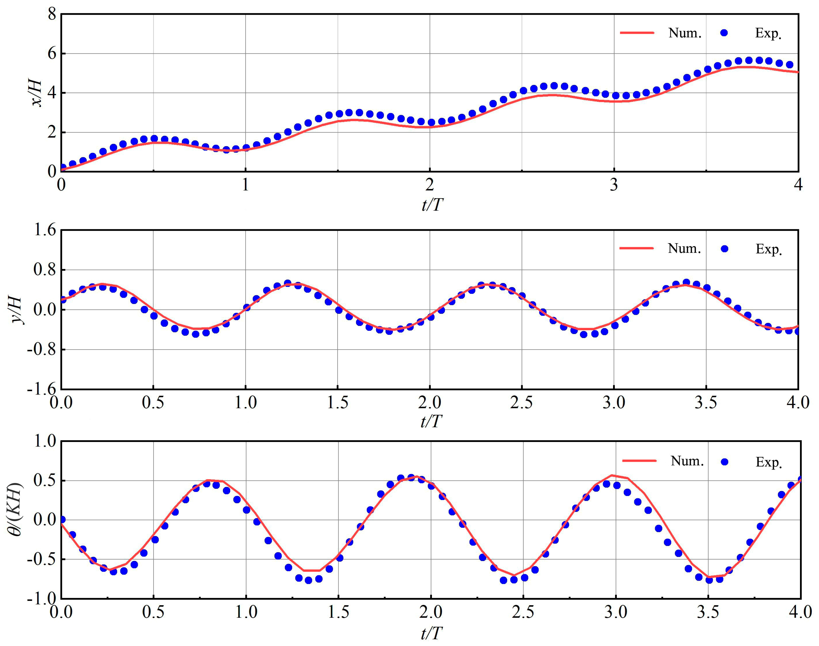
3.2. Floating Body Motion Response Verification

Numerical simulations were conducted in a two-dimensional wave tank, similar to the physical model tests conducted by He [15]. The numerical simulation setup is shown in Figure 6. The numerical wave tank has a length of 25 m, a width of 0.42 m, and a height of 0.8 m. The wave generation boundary is set on the left side of the tank, and a free-floating rectangular box is arranged 8.5 m from the wave generation boundary. The box is 0.3 m in width, 0.2 m in height, and has an initial draft of 0.1 m, with a moment of inertia about its center of a mass of 0.1365 kg·m2. The wave height is set as 0.10 m with a period of 1.2 s, and numerical relaxation zones of 3.5 m each are set at both the starting and ending ends of the wave tank.
Figure 7 shows the time history curves of the roll, heave, and sway motions of the floating body in waves over multiple periods. The sway and heave motions are defined as positive in the positive direction of the x and y axes, respectively, and the roll motion is defined as positive in the counterclockwise direction around the z-axis. The results show that for the sway motion, the numerical results are slightly lower than the experimental data, with the maximum difference occurring at the positive peak. For the heave motion, the two results are basically consistent, with the simulated amplitude slightly smaller than that of the experiment. For the roll motion, the numerical results are generally slightly larger than the experimental data, with a larger difference during the downward phase. Overall, the numerical simulations for the three degrees of freedom of the floating body motion responses show good agreement with the experimental data. In general, the error between the numerical results and experimental data is mainly from the experimental errors (measurement value of moment of inertia and wave height) and numerical diffusion.

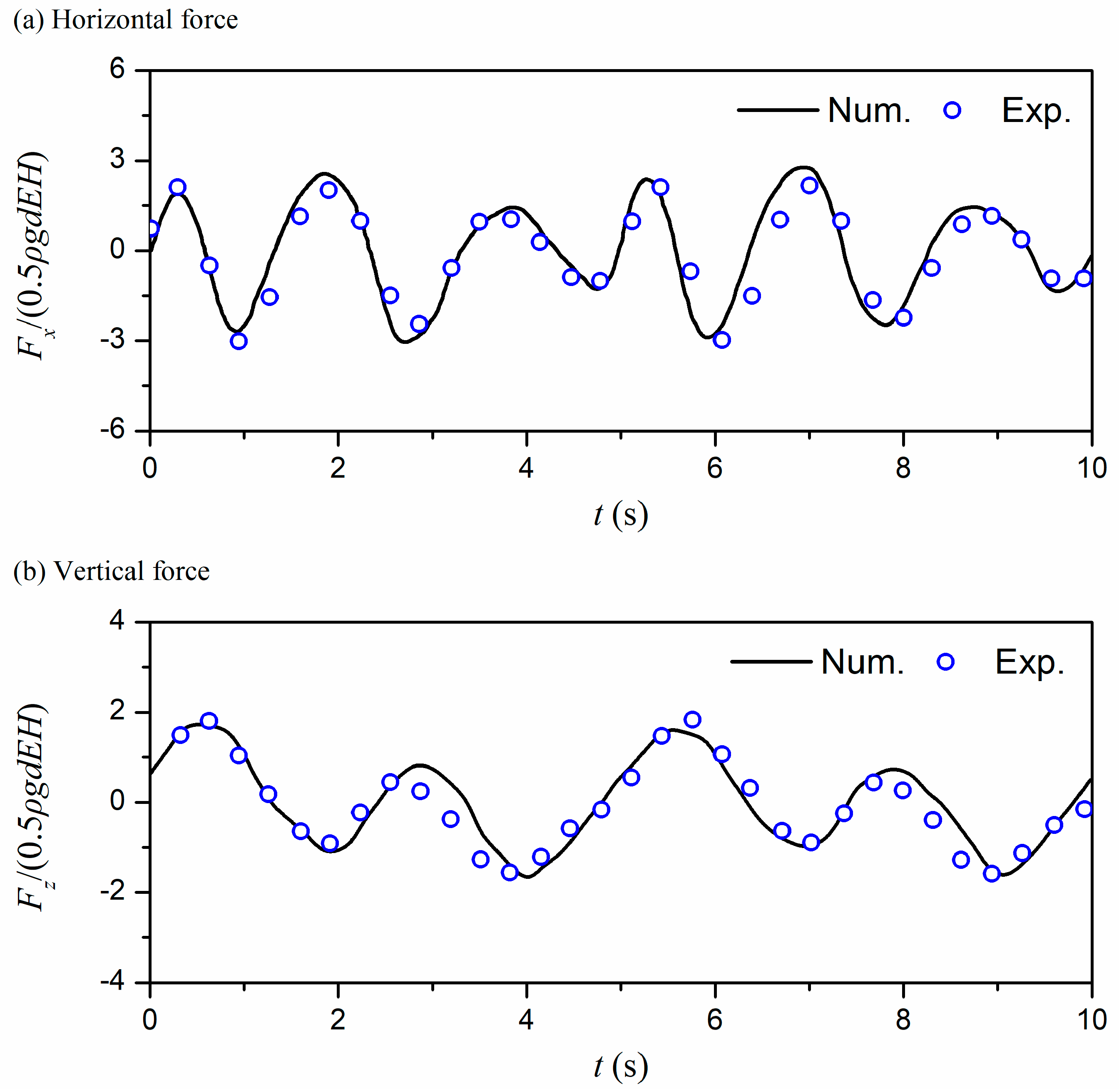
3.3. Wave Force Verification

The floating body in the numerical model experiences forces that are compared to a set of physical model tests conducted by Wang and Zou [16]. The numerical model setup is shown in Figure 8. The model width is 0.6 m, the length is 0.4 m, and the draft is 0.24 m, with an incident wave height of H = 0.06 m and a wave period of T = 5 s. Figure 9 compares the experimental and numerical results of wave forces on the ship cross-section. In general, the numerical model is suitable for calculating the wave force on the ship cross-section. The error between numerical results and experimental data is mainly from the strong nonlinear wave field between the ship cross-section and the ending-wall of the wave tank.

4. Results and Discussion

Hydrodynamic load and motion response are the first considerations for the design of the immersed tunnel. Yang et al. [17] conducted a series of experimental tests to analyze the motion response and hydrodynamic characteristics of the submerged floating tunnel with one-degree-of-freedom vertically elastically truncated boundary condition under the wave action. In this study, numerical simulations were conducted on the immersed tunnel using the previously validated numerical model that couples floating body motion with the wave field, considering the influence of regular and irregular waves. The study explored the effects of wave height and wave period on the roll motion response of the immersed tunnel and the wave forces.

4.1. Hydrodynamic Characteristics of the Immersed Tunnel in Regular Waves

Regular waves are generated using Stokes first-order wave theory. By comparing the changes in the roll angle of the immersed tunnel and the force conditions, the effects of wave height and wave period on the motion response and force status of the immersed tunnel under regular waves are analyzed. The water depth is 0.8 m, and the range of wave periods is from 1.0 s to 1.8 s, and the wave heights range from 0.02 m to 0.08 m, as shown in Table 2.

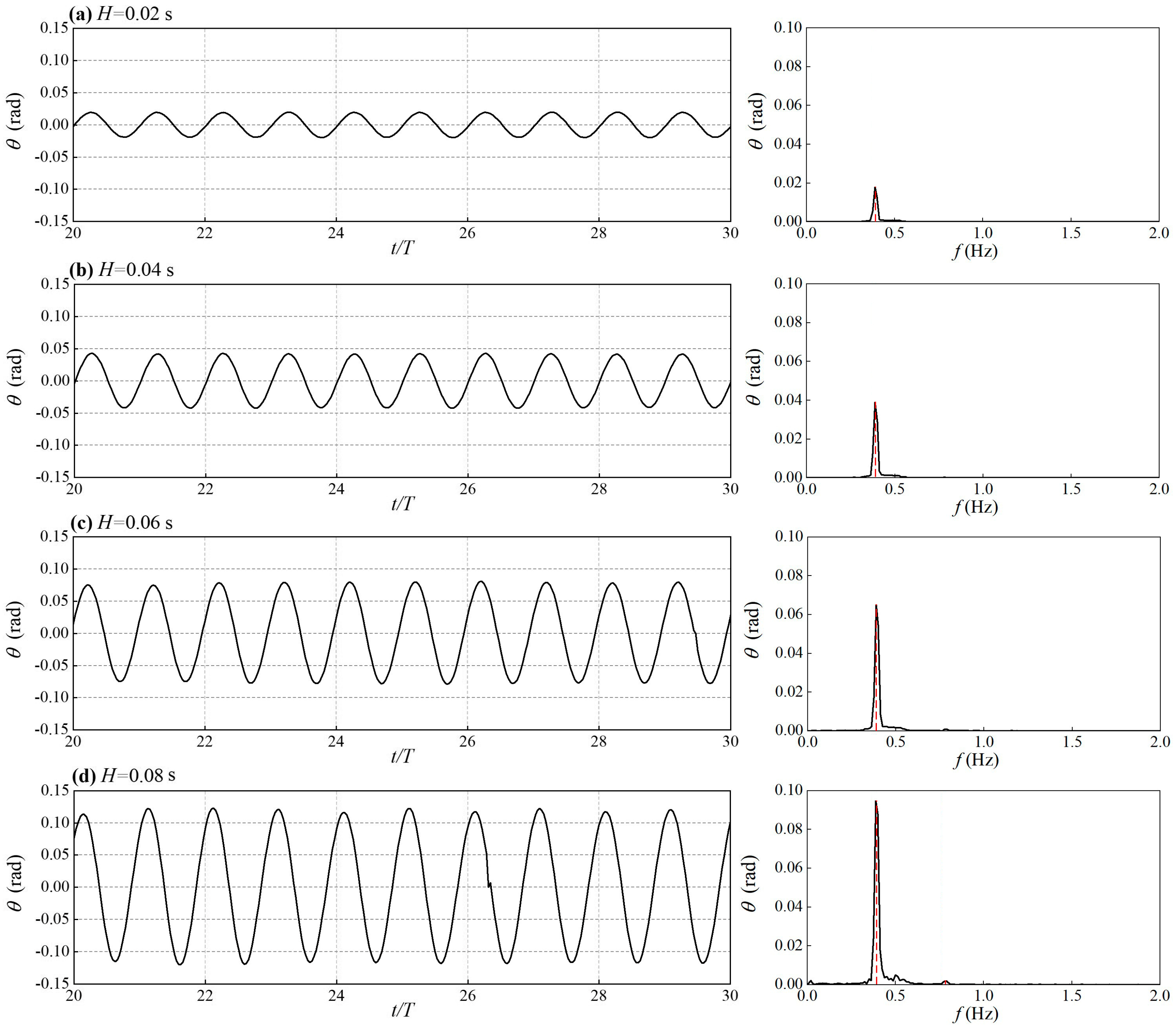
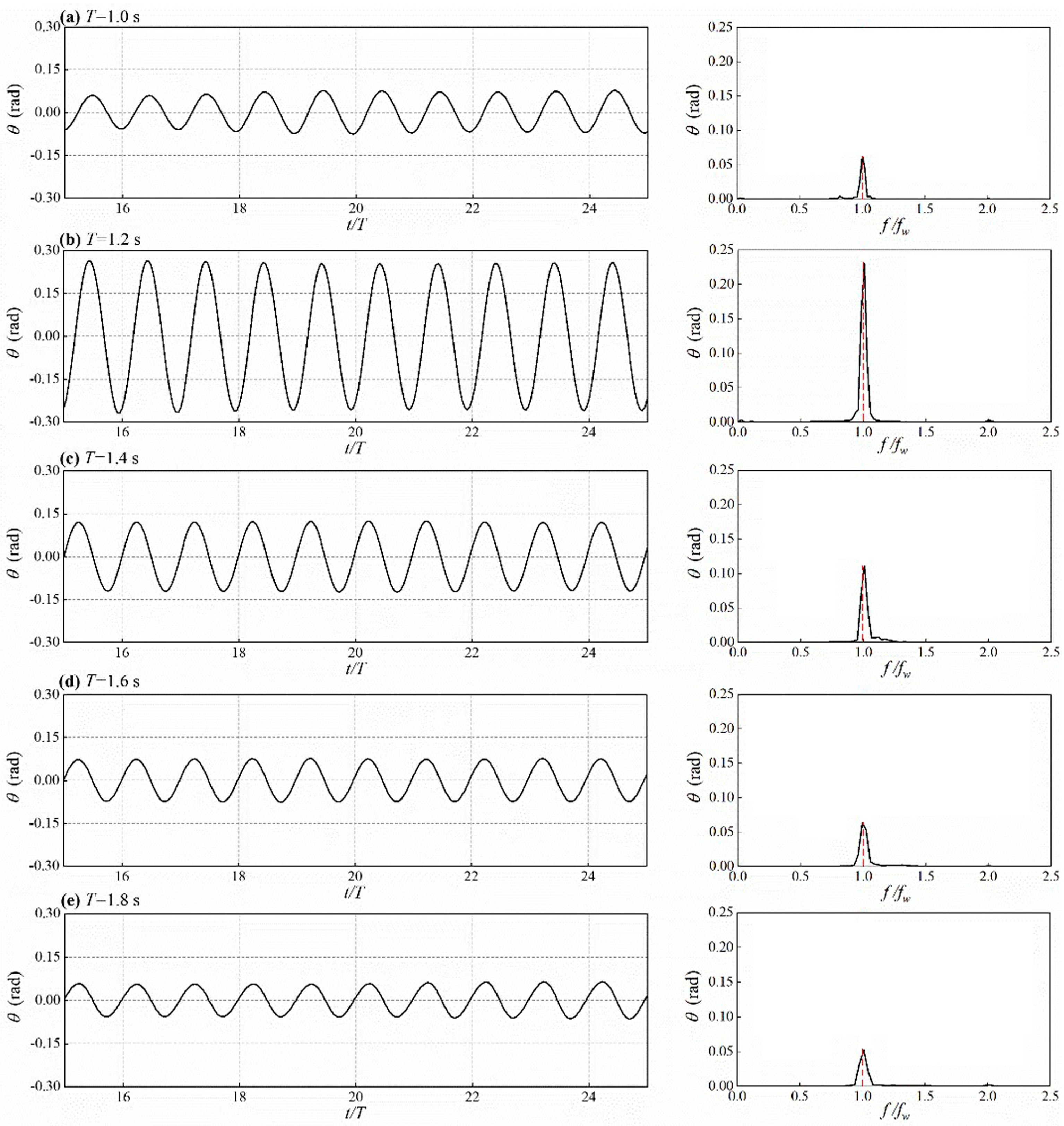
4.1.1. Analysis of Roll Motion Response

Figure 10 shows the time histories of the roll motion of the floating body for different wave heights when the wave period T = 1.6 s.
To investigate the effect of wave period on the roll motion response of the floating body, five kinds of wave conditions with wave heights of H = 0.06 m and wave periods of T = 1.0 s, 1.2 s, 1.4 s, 1.6 s, and 1.8 s were considered. Figure 11 presents the time histories of the roll motion for different wave periods. The results indicate that the immersed tunnel undergoes regular vibrations, with a symmetrical amplitude range around the equilibrium position. The maximum roll angle of 0.23 rad is observed at a wave period of 1.2 s, and the amplitude gradually decreases as the wave period increases.
The free decay test of the roll motion of the immersed tunnel shows that the initial angle is set at −3°. Figure 12 illustrates the time histories of the free decay roll motion and its amplitude spectrum. The inherent frequency of the roll motion is found to be fn = 0.85 Hz, which corresponds to a natural period Tn = 1.18 s. The maximum roll motion response occurs at a wave period of T = 1.2 s, indicating that this is due to the wave period being close to the natural period of the immersed tunnel structure.
The velocity contour plots at typical moments within one wave period for wave periods T = 1.2 s and T = 1.6 s are compared in Figure 13. The time points are defined as t1 = t0, t2 = t0 + 0.25T, t3 = t0 + 0.5T, t4 = t0 + 0.75T, and t5 = t0 + T. At time t1, the tilt angle of the immersed tunnel structure reaches its maximum in the counterclockwise direction. Under the influence of the clockwise wave moment, the immersed tunnel begins to rotate clockwise. At time t2, the immersed tunnel reaches a horizontal position. At time t3, the clockwise tilt angle of the tunnel reaches its maximum, after which it begins to rotate counterclockwise under the influence of the counterclockwise wave moment. At time t4, the tunnel structure returns to a horizontal position and continues to rotate counterclockwise, reaching the same motion state as at t1 at time t5. It is evident that the roll motion angle of the immersed tunnel at a wave period of 1.2 s is significantly greater than that at a wave period of 1.6 s. This further confirms that when the wave period is close to the natural period of the floating body structure, the motion response of the floating body is significantly enhanced.

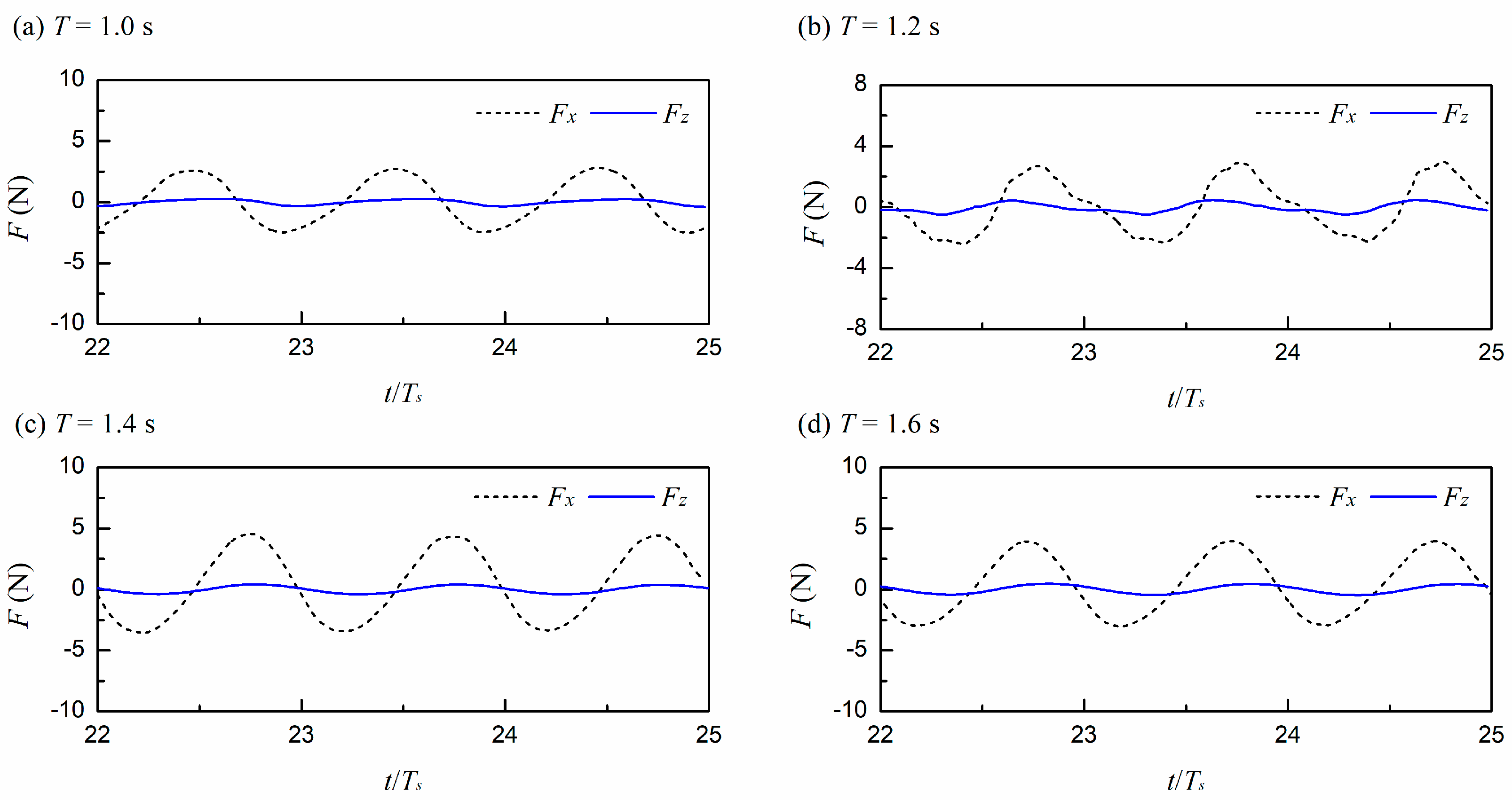
4.1.2. Analysis of Wave Forces

The horizontal and vertical wave forces acting on the immersed tunnel are non-dimensionalized as F x and F z , respectively. The horizontal wave force F x and vertical wave force F z acting on the immersed tunnel can be represented as follows:
F x = f x / 0.5 ρ g d A H
F z = f z / 0.5 ρ g B A H
Figure 14 shows the time histories of the horizontal and vertical forces acting on the immersed tunnel when the wave period is T = 1.6 s and for different wave heights. As observed, with the increase in wave height, the non-dimensional horizontal force amplitude increases from 2.74 to 5.12, while the non-dimensional vertical force amplitude remains between 0.40 and 0.48. The horizontal force is approximately 7 to 10 times greater than the vertical force. At a wave height of 0.08 m, it can be seen that the slope of the rising section of the horizontal force is slightly less than that of the descending section, while the slope of the rising section of the vertical force is slightly greater than that of the descending section. In summary, as the incident wave height increases, the horizontal force amplitude significantly increases, while the vertical force amplitude remains largely unchanged, indicating a nonlinear enhancement of the forces acting on the immersed tunnel.
Figure 15 presents the time histories of the horizontal and vertical forces on the immersed tunnel when the wave height is 0.06 m. It indicates that the non-dimensional horizontal force amplitude ranges from 2.90 to 4.64, while the non-dimensional vertical force amplitude varies from 0.28 to 0.53. When the wave period approaches the natural period of the immersed tunnel, which is 1.18 s, the instability of the forces acting on the tunnel becomes evident. However, the overall force pattern remains regular; at the start of the wave cycle, the forces on the floating body remain around zero for a period, particularly with the vertical force oscillating around zero for nearly one-fifth of the wave cycle. This indicates that as the wave period increases, the horizontal and vertical force amplitudes experience slight increases, and the force variations become more complex as they approach the natural period of the floating body.

4.2. Hydrodynamic Characteristics of the Immersed Tunnel in Irregular Waves

By observing the roll angle and the forces acting on the floating body, the study investigates the influence of wave height on the motion response and force status of the immersed tunnel in irregular waves. The wave conditions for irregular wave simulations are shown in Table 3. The water depth is 0.8 m.

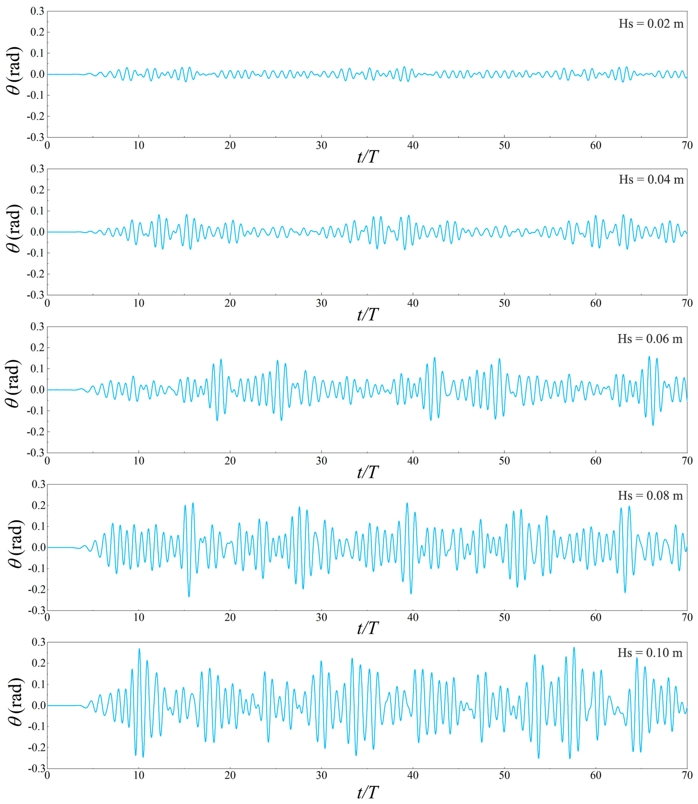
4.2.1. Analysis of Roll Motion Response

Figure 16 illustrates the time histories of the roll motion of the immersed tunnel in irregular waves with a significant wave period Ts = 1.6 s and significant wave heights ranging from 0.02 m to 0.10 m. The results show that the average amplitude of the roll motion of the immersed tunnel increases with the increase in significant wave height, significantly exceeding the amplitudes observed under regular waves at the same heights, by approximately 2 to 3 times (Table 4). It indicates that the instability of the wave elevation for irregular waves leads to a more intense and unstable motion response of the immersed tunnel.
Figure 16 shows that after one to two cycles of strong oscillation, the amplitude of the floating body quickly decays to a value between one-third and one-half of its previous value. Three types of behaviors are noted: the first shows a linear increase in the oscillation amplitude, indicating a gradual strengthening or weakening of the motion; the second involves abrupt changes in the amplitude, with some cases showing sudden decreases or increases, indicating rapid stabilization or intense shaking; the third displays a consistent amplitude, suggesting a regular motion characteristic of regular wave influence.

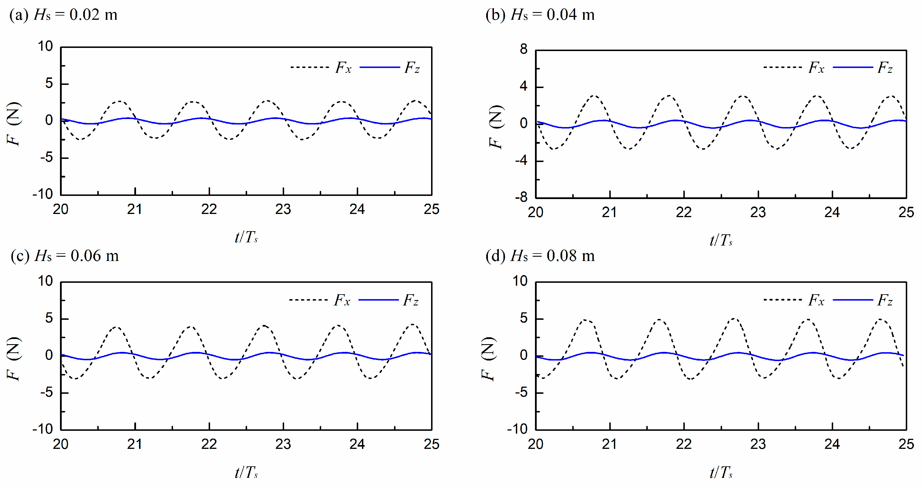
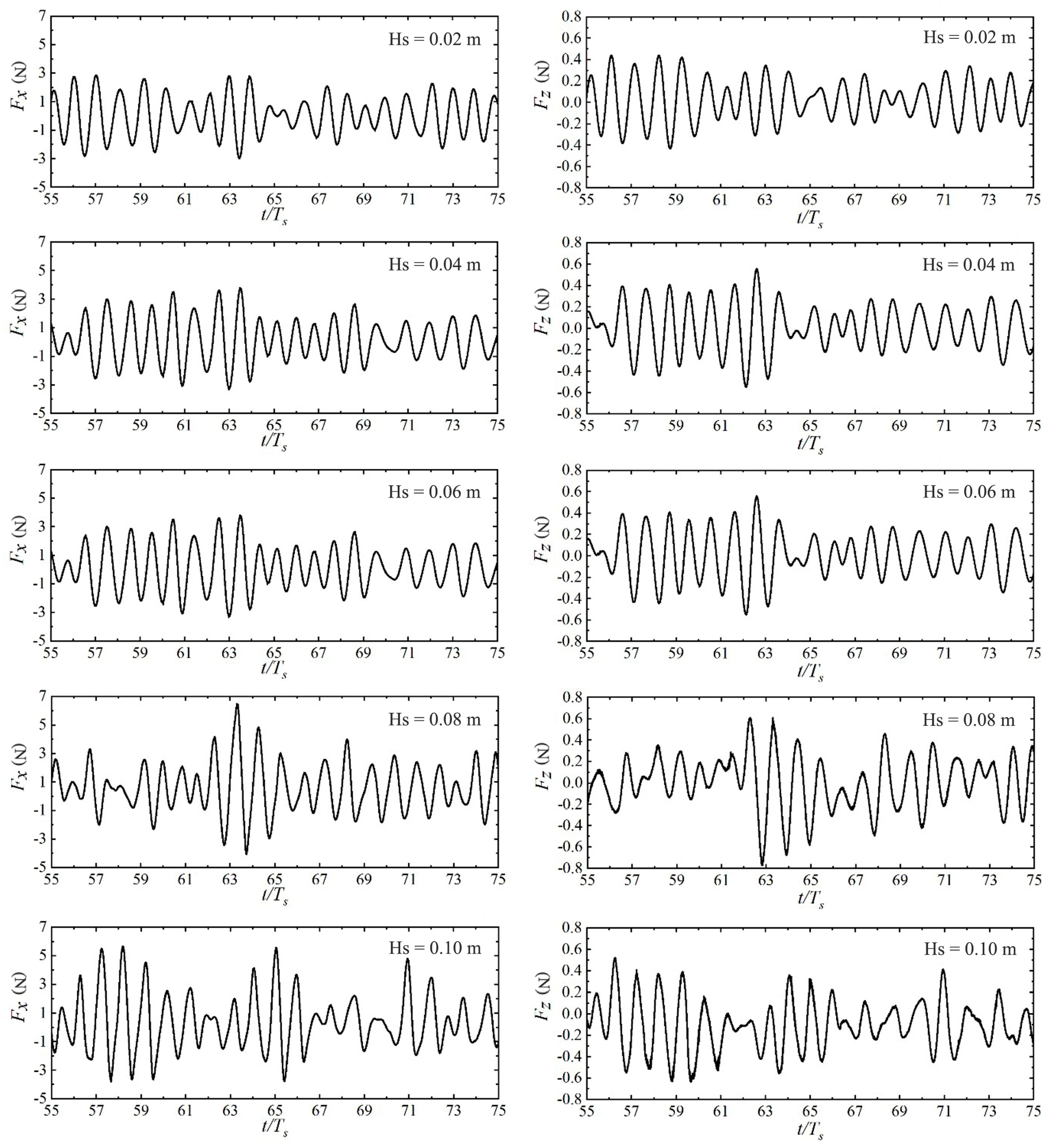
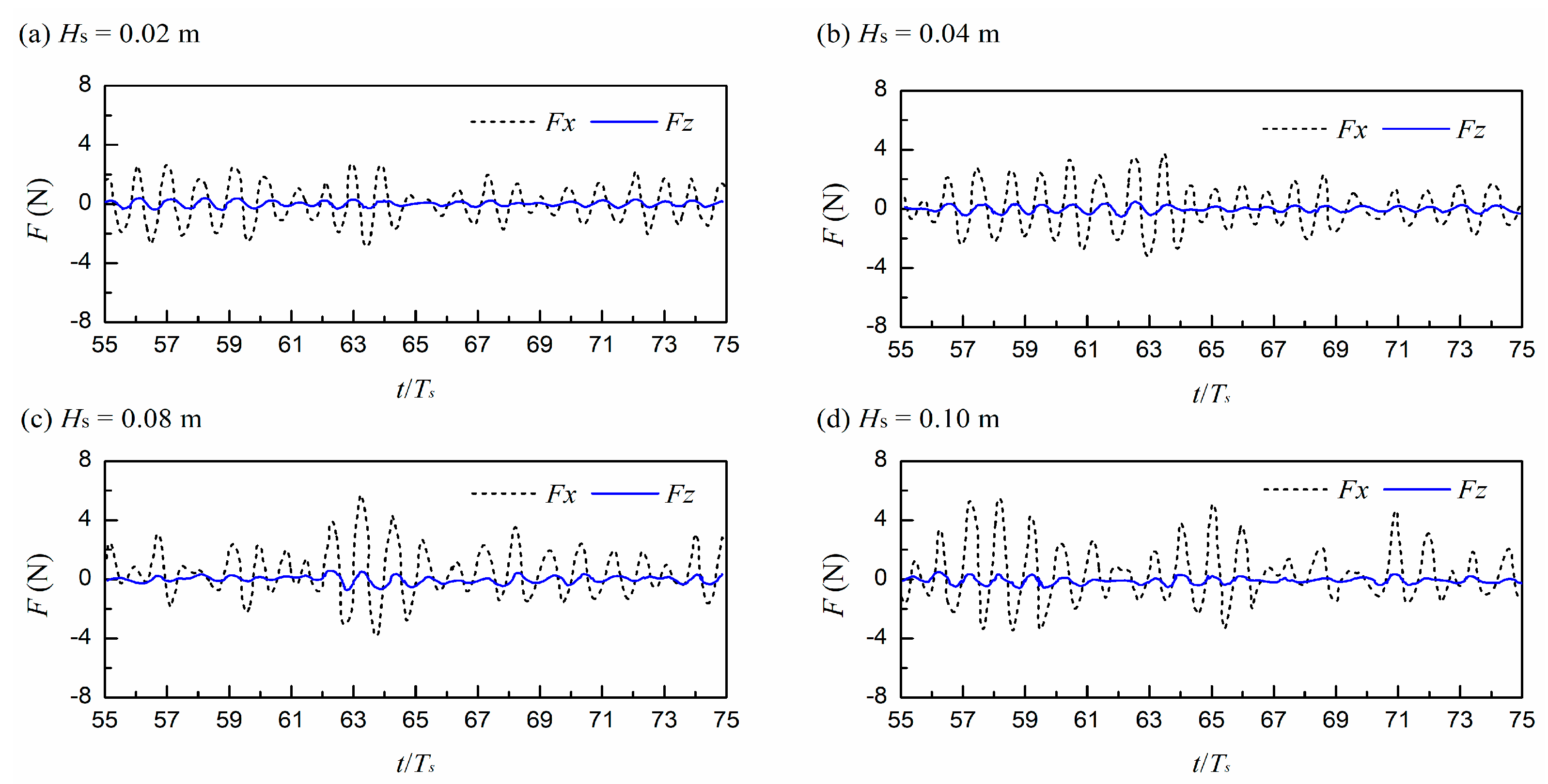
4.2.2. Analysis of Wave Forces

Figure 17 shows the time histories of the horizontal and vertical forces acting on the immersed tunnel for different significant wave heights. It can be observed that, under similar conditions, the horizontal forces acting on the tunnel are much greater than the vertical forces. By examining the variations in amplitude, it can be seen that there is a degree of synchronization between the horizontal and vertical forces.
As shown in Figure 18, periods with large horizontal forces coincide with periods of relatively large vertical forces, and vice versa. The results show that the average amplitude of the horizontal forces acting on the tunnel model increases as the significant wave height increases. The difference between the amplitudes of roll motion of immersed tunnel in irregular and regular waves is not significant, and the changes in the vertical forces on the immersed tunnel remain minor.

5. Conclusions

A numerical model based on the OpenFOAM was established to simulate the coupled motion of floating bodies in wave fields using an overset mesh method. By comparing the numerical results with existing experimental data, the accuracy of this numerical model of simulating the motion of floating bodies and the wave forces on structures was verified. In addition, the roll motion and force of the immersed tunnel were investigated for different wave heights and wave periods. For the regular waves, as the wave height increases, the roll motion and the horizontal force amplitude increase significantly, and the vertical force amplitude is basically unchanged. When the wave period is close to the natural period of the immersed tunnel, the roll motion reaches its maximum value. For the irregular waves, as the significant wave height increases, the amplitude of the roll motion increases, which is greatly larger than the roll motion observed in regular waves at the same wave height (by a factor of approximately 2 to 3). Furthermore, the average amplitude of the horizontal forces increases, though there is a small difference compared to the forces in regular waves at the same wave height.

Author Contributions

Software, H.S.; resources, X.J.; data curation, T.X.; writing—original draft preparation, H.S. and X.J.; writing—review and editing, T.X. and W.Z. All authors have read and agreed to the published version of the manuscript.

Funding

This work was financially supported by the National Key R&D Program of China (No. 2021YFB2400605).

Data Availability Statement

The data presented in this study are available on request from the corresponding author.

Conflicts of Interest

Author Hang Shi was employed by the company China Ship Wind Power Clean Energy Technology (Beijing) Co., Ltd. Author Xianlin Jia was employed by the company PowerChina Huadong Engineering Corporation Limited. Author Tiaojian Xu and Wo Zhang were employed by the company State Key Laboratory of Coastal and Offshore Engineering, Dalian University of Technology. The remaining authors declare that the research was conducted in the absence of any commercial or financial relationships that could be construed as a potential conflict of interest.

References

  1. Chen, K.; Peng, S.; Wu, W. Model test of immersed tunnel element in towing tank in winds, waves and currents. In Proceedings of the 22nd International Offshore and Polar Engineering Conference, Rhodes, Greece, 17 June 2012. [Google Scholar]
  2. Peng, S.; Wu, W.; Chen, K. Experimental Investigation on Element Immersing Process of Immersed Tube Tunnel of Hong Kong-Zhuhai-Macao Bridge. In Proceedings of the ASME 2012 31st International Conference on Ocean, Offshore and Arctic Engineering, Rio de Janeiro, Brazil, 1 July 2012. [Google Scholar]
  3. Wu, R.D.; Ying, Z.Q.; Wang, Z. Model Test for Hydrodynamic Parameters of Immersed Tube Tunnel in Static Water. Appl. Mech. Mater. 2014, 477, 754–758. [Google Scholar]
  4. Cozijn, H.; Heo, J.W. Analysis of the tunnel immersion for the Busan-Geoje Fixed Link Project through scale model tests and computer simulations. In Proceedings of the 8th International Conference on Ocean, Offshore and Arctic Engineering-OMAE 2009, Honolulu, HI, USA, 31 May 2009. [Google Scholar]
  5. Partha, C.; Subrata, K.C.; Tommy, O.; Koo, I.S. Dynamic simulation of immersion of tunnel elements for Busan-Geoje Fixed Link Project. In Proceedings of the 27th International Conference on Offshore Mechanics and Arctic Engineering 2008, San Francisco, CA, USA, 25 June 2008; Volume 4. [Google Scholar]
  6. Jensen, O.P.; Olsen, T.H.; Kim, C.; Heo, J.W.; Yang, B. Construction of immersed tunnel in offshore wave conditions Busan-Geoje project South Korea. Tunn. Undergr. Space Technol. 2006, 21, 333. [Google Scholar] [CrossRef]
  7. Hakkaart, C.J.A. Transport of tunnel elements from Baltimore to Boston, over the Atlantic Ocean. Tunn. Undergr. Space Technol. 1996, 11, 479–483. [Google Scholar] [CrossRef]
  8. Gong, S.K.; Gao, J.L.; Yan, M.Y.; Song, Z.W.; Shi, H.B. Effects of floater motion on wave loads during steady-state gap resonance occurring between two non-identical boxes. Ocean. Eng. 2025, 323, 120649. [Google Scholar] [CrossRef]
  9. Aono, T.; Sumida, K.; Fujiwara, R. Rapid stabilization of the immersed tunnel element. In Proceedings of the Coastal Structures 2003 Conference, Portland, OR, USA, 26–30 August 2003. [Google Scholar]
  10. Kasper, T.; Steenfelt, J.S.; Pedersen, L.M. Stability of an immersed tunnel in offshore conditions under deep water wave impact. Coast. Eng. 2008, 55, 753–760. [Google Scholar]
  11. Wu, Z.W.; Liu, J.K.; Liu, Z.Q. Nonlinear wave forces on large-scale submerged tunnel element. Mar. Struct. 2016, 45, 133–156. [Google Scholar] [CrossRef]
  12. Bhatt, R.B.; Dukkipati, R.V. Advanced Dynamics; Alpha Science International, Ltd.: Oxford, UK, 2001; pp. 213–219. [Google Scholar]
  13. Goda, Y. A comparative review on the functional forms of directional wave spectrum. Coast. Eng. J. 1999, 41, 1–20. [Google Scholar] [CrossRef]
  14. Charkrabarti, S.K. Offshore Structure Modeling; World Scientific Publishing: Singapore, 1994. [Google Scholar]
  15. He, M. Study on the Dynamic Response of a New Type of Floating Combined Structure Under Wave Action. Doctoral Dissertation, Dalian University of Technology, Dalian, China, 2016. (In Chinese). [Google Scholar]
  16. Wang, D.G.; Zou, Z.L. Study of non-linear wave motions and wave forces on ship sections against vertical quay in a harbor. Ocean. Eng. 2007, 34, 1245–1256. [Google Scholar] [CrossRef]
  17. Yang, Z.W.; Li, J.Z.; Xu, Y.W.; Ji, X.R.; Sun, Z.X.; Ouyang, Q.N.; Zhang, H.Q. Experimental study on the wave-induced dynamic response and hydrodynamic characteristics of a submerged floating tunnel with elastically truncated boundary condition. Mar. Struct. 2023, 88, 103339. [Google Scholar]
Figure 1. Setup of numerical model for the immersed tunnel in waves.
Water 17 01094 g001
Figure 2. Mesh arrangement for numerical simulation of the immersed tunnel in waves.
Water 17 01094 g002
Figure 3. Comparison of horizontal forces on the immersed tunnel for different mesh sizes.
Water 17 01094 g003
Figure 4. Comparison of vertical forces on the immersed tunnel for different mesh sizes.
Water 17 01094 g004
Figure 5. Comparison of roll motion of the immersed tunnel for different mesh sizes.
Water 17 01094 g005
Figure 6. Setup of numerical wave tank for floating body in waves.
Water 17 01094 g006
Figure 7. Comparison of numerical and experimental floating body motion trajectories (K is wave number, H is wave height, the experimental data are from He [15]).
Water 17 01094 g007
Figure 8. Setup of the numerical wave tank for wave force verification.
Water 17 01094 g008
Figure 9. Comparison of numerical and experimental wave forces on the ship cross-section.
Water 17 01094 g009
Figure 10. Comparison of roll motion for different wave heights. (Red line represents the peak frequency).
Water 17 01094 g010
Figure 11. Comparison of roll motion for different wave periods. (Red line represents the peak frequency).
Water 17 01094 g011
Figure 12. Free attenuation curve and amplitude spectrum of roll motion of immersed tunnel. (Red line represents the peak frequency).
Water 17 01094 g012
Figure 13. Velocity contours around immersed tunnel for the typical moments.
Water 17 01094 g013
Figure 14. Time histories of horizontal and vertical forces on the immersed tunnel for different wave heights.
Water 17 01094 g014
Figure 15. Time histories of horizontal and vertical forces on the immersed tunnel for different wave periods.
Water 17 01094 g015
Figure 16. Comparison of roll motion of the immersed tunnel for different significant wave heights.
Water 17 01094 g016
Figure 17. Time histories of horizontal and vertical forces on the immersed tunnel for different significant wave heights.
Water 17 01094 g017
Figure 18. Synchronization of horizontal and vertical forces on the immersed tunnel for different significant wave heights.
Water 17 01094 g018
Table 1. Details of meshes for numerical simulation of the immersed tunnel in waves.
λxHzNumber of Meshes
Mesh I601669,187
Mesh II801879,615
Mesh III1002090,041
Table 2. Parameters of the regular waves used in the numerical simulation.
No.Draft (m)Wave Period (s)Wave Height H (m)
10.091.60.02
20.091.60.04
30.091.60.06
40.091.60.08
50.091.00.06
60.091.20.06
70.091.40.06
80.091.60.06
90.091.80.06
Table 3. Parameters of irregular waves for the numerical simulations.
No.Draft
d (m)
Significant Wave Period
Ts (s)
Significant Wave Height
Hs (m)
10.091.60.02
20.091.60.04
30.091.60.06
40.091.60.08
50.091.60.10
Table 4. Comparison of roll motion amplitudes for regular and irregular waves (Unit: °).
Wave TypeWave Height
0.02 m0.04 m0.06 m0.08 m
Regular wave−0.02~0.02−0.04~0.04−0.07~0.07−0.09~0.09
Irregular wave−0.05~0.05−0.08~0.10−0.18~0.16−0.24~0.23
Disclaimer/Publisher’s Note: The statements, opinions and data contained in all publications are solely those of the individual author(s) and contributor(s) and not of MDPI and/or the editor(s). MDPI and/or the editor(s) disclaim responsibility for any injury to people or property resulting from any ideas, methods, instructions or products referred to in the content.

