1. Introduction
Due to the increasing frequency of extreme weather events, characterized by intense rainfall and prolonged droughts, the number of water-related natural disasters is rising [
1]. These include both hydrological events, such as floods, and geomorphological processes, including landslides and soil erosion, often triggered by water activity. The interaction between flooding and erosion has also been evident many times in Slovenia, as shown during the extreme flood event in August 2023, where torrential processes caused significant landscape changes despite implemented mitigation measures [
2]. Recent studies also highlight that such events significantly alter sediment dynamics and erosion patterns at the basin scale [
3,
4].
Given the frequency and risks posed by water-related extreme events, the EU adopted the Floods Directive (FD) [
5] to protect people, their activities, and the environment against floods, providing guidelines for preparing flood hazard maps. Despite the proposed holistic approach, FD only briefly recommends adding information on sediment impacts when producing flood maps (i.e., in Article 6.5d).
The FD has been transposed into the legal frameworks of Member States. In Slovenia, for example, flood-prone areas are classified into four flood hazard classes (high, medium, low, and residual) and three erosion hazard classes (high, medium, and low), in accordance with rules adopted by the Government of the Republic of Slovenia in 2007 [
6]. For each sub-area, conditions and restrictions for construction and spatial development are prescribed by a special decree [
7]. This legislation defines the role of hydrological and hydraulic modelling and provides a methodology for producing hazard maps.
Flood mapping is crucial for flood risk assessment, as it represents the foundation for emergency response planning, resource allocation, and infrastructure development in flood-prone regions [
8,
9]. There are more data sources and approaches to flood mapping: (i) empirical analysis of historical data (i.e., past events), (ii) geomorphological mapping supported by aerial-photo interpretation, field evidence of flooding and river dynamics, and (iii) model-based mapping, derived from hydrological–hydraulic modelling [
3,
8,
9]. Empirical flood mapping lacks theoretical foundations and may thus lead to uncertain and inaccurate flood predictions. On the other hand, physically based flood mapping usually employs advanced remote sensing techniques to observe and analyze terrain characteristics, and simulate water flow and its interaction with the landscape. Using hydrological–hydraulic models in combination with field measurements, we can simulate more realistic flood events and thus obtain more accurate flood maps [
10].
Despite progress in flood hazard mapping, erosion hazard mapping is less mature. However, recent developments in hydrodynamic and morphodynamic numerical models provide opportunities to explicitly incorporate sediment transport in flood hazard analysis [
3,
11,
12].
Hydraulic modelling is based on fundamental hydromechanical and hydraulic principles, including equations for open-channel flow. In the context of erosion, shear forces and flow velocities are crucial, controlling the sediment transport capacity of water. Advanced models that enable the simulation of complex flow–sediment interactions using two-dimensional (2D) or coupled morphodynamic approaches [
13,
14], such as MIKE21 [
15], Delft3D [
16], TELEMAC-MASCARET (
https://www.opentelemac.org/ (accessed on 8 October 2025)), and HEC-RAS [
17] can provide detailed insights into spatial patterns of shear stress and bed-level changes during flood events. Still, issues as data availability (e.g., detailed bed-load transport measurements), model validation, the need for standardized methodologies, and knowledge gaps in understanding physical processes responsible for morphodynamic changes pose ongoing obstacles [
9].
In this research, we will use HEC-RAS, a well-established tool for hydraulic simulation of rivers, and frequently used in water management, hydro-environmental engineering, and research [
18,
19,
20]. It was developed within the Hydrologic Engineering Center (HEC), part of the U.S. Army Corps of Engineers (USACE), and became publicly available in 1995 [
17]. The initial versions supported only one-dimensional (1D) steady flow calculations, but subsequent upgrades soon enabled 1D unsteady flow modelling. HEC-RAS 4.0 introduced sediment transport and water quality modelling and included the RAS Mapper extension, a built-in GIS viewer that simplified the visualization of modelling results. A significant enhancement followed in 2016 with the addition of 2D unsteady flow modelling. The latest major update, released with version 6 in 2021, introduced 2D sediment transport modelling and simulation of debris and mudflows. Despite these capabilities, its application for simulating sediment transport and erosion processes in research studies remains relatively limited globally, with only a few case studies demonstrating its potential in this field [
21,
22,
23,
24].
While in Slovenia, the procedure for creating flood hazard maps based on hydraulic modelling is well-defined and allows little deviation [
6], the production of erosion hazard maps remains empirical, primarily based on engineering assumptions and coarse field survey data due to the absence of a clearly standardized methodology. Additionally, while most existing studies on sediment transport focus on in-channel processes, floodplain erosion, particularly during high-magnitude floods, remains understudied [
25,
26,
27].
Thus, the major novelty of this study is the improvement of the current empirical procedure for developing erosion hazard maps by incorporating a model-based approach, with a special focus on the floodplains. Leveraging the growing capabilities of hydraulic modelling software, we explored the potential of erosion hazard representation using a 2D hydraulic sediment transport model, with the Selška Sora River (Slovenia) as a case study. In addition to hydraulic variables, the model incorporates soil composition characteristics, which significantly influence the extent of erosion in flooded areas. The results provide a basis for identifying erosion-prone zones and classifying areas according to erosion hazard levels, set by current legislation [
6].
The approach presented here not only advances methodologies for mapping erosion hazards in floodplains but could also be potentially applied in EU-wide flood and erosion hazard assessment frameworks. By integrating 2D hydraulic and sediment transport modelling with spatial soil characteristics, the method can complement existing flood hazard maps, offering a more detailed understanding of the erosion/deposition processes in erosion-prone areas [
28,
29]. Such insights can support spatial planning, risk mitigation strategies, and informed decision-making in other river basins with similar hydro-morphological characteristics.
2. Materials and Methods
2.1. Study Area and Input Data
The Selška Sora River valley lies in the southwestern foothills of the Julian Alps. It extends from west to east. In addition to the main valley, it consists of narrow side valleys of torrential tributaries. The steep slopes of the upstream watershed area (56.56% on average) and rugged terrain indicate a high potential for erosion processes.
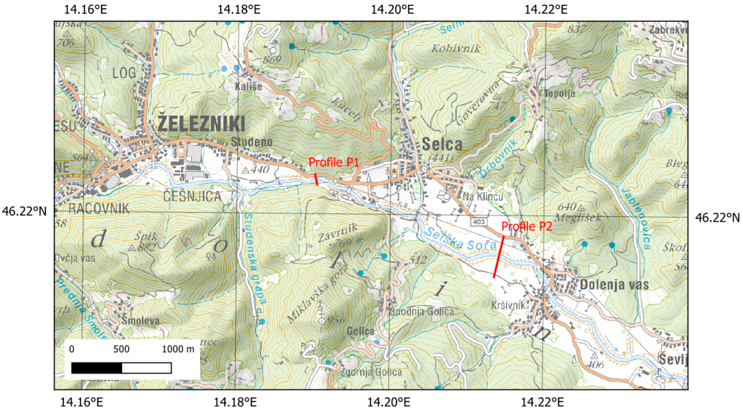
The specific area under study is a 4.5 km long section of the Selška Sora River, between the city of Železniki and the settlement of Dolenja Vas (
Figure 1).
The input data used for 2D modelling consisted of topographic data, geological and pedological characteristics of the soil, land use, and hydrological/hydraulic boundary conditions (
Table 1).
For the basic topography, we used LIDAR data with a resolution of 1 m
2, freely available through the Slovenian Environmental Agency online viewer [
30]. In the river channel, a more detailed terrain was used, based on geodetic survey measurements provided by IZVO-R d.o.o. [
31].
The bottom of the valley was formed on alluvial deposits of the Selška Sora River and its tributaries. The lithology of the sediments along the valley is diverse. Upstream, claystones, marlstones, and limestones dominate, while downstream, the slopes transition into Triassic and Jurassic limestones and dolomites. Different soil types have developed on the various bedrock formations. For example, the alluvial valley floor is covered by eutric fluvisols [
31].
To model sediment transport, layer thicknesses and grain size distribution are also needed. In this context, we relied on a report prepared by the IRGO Consulting d.o.o. [
32]. As part of this report, the thickness of the clayey–silty soil layer on grassland areas was determined (i.e., 1.5 to 2.5 m). Beneath this lies a 5- to 7-m thick layer of silty to clayey gravel, and below that, the bedrock consists of limestone, shale, marl, or claystone. For the upper soil layer, the grain size distribution was also determined at a depth between 0.3 and 0.7 m.
Data on land use were provided by the Ministry of Agriculture, Forestry, and Food [
33]. The analysed river section begins at the transition between built-up areas and permanent grasslands. Along the river channel, there are isolated strips of forest, overgrown agricultural land, and built-up areas. The widened valley bottom is primarily composed of arable land and meadows, interspersed with orchards, while the hills are covered in forest.
Table 2 provides a summary of the land use categories within the computational domain, presented in both hectares and percentage coverage.
The total watershed area of the Selška Sora River covers 224 km
2. Annual peak flows occur in autumn, due to intense rainfall. During winter, the water level of the Selška Sora is lower, while in spring, it rises again, primarily due to snowmelt in the upper catchment areas. Minimum flows are recorded between June and August [
34].
In the studied section, the Selška Sora River meanders across meadows and farmland areas, which act as inundation zones during flood events. The channel width ranges from 10 m upstream to 15 m downstream. The riverbanks are mostly natural and overgrown with shrubs. In some places, the riverbed elevation is stabilised with rock and log sills and check dams.
Due to its pronounced torrential character, the Selška Sora poses a flood risk to a large portion of the lowland areas. The area under study was most severely affected by torrential flooding on 18 September 2007, when the river discharge exceeded 300 m
3/s [
35,
36]. The flood resulted in extensive material damage and loss of human lives, necessitating a prolonged rehabilitation of the affected areas. As part of subsequent water management planning, several studies were conducted. Flood hazard maps were produced [
31] and subsequently used for calibrating the hydraulic model developed in this study. In addition, the hydrological analysis was updated [
37].
2.2. Hydraulic Software HEC-RAS
Geometric data represent the core of all hydraulic modelling software. In 2D simulations, where a detailed representation of river channel and floodplain water flow dynamics is required, the primary input is detailed bathymetry acquired by ultrasonic measurements and a Digital Elevation Model (DEM) that accurately describes the riparian and inundation terrain.
For building a representative model geometry, HEC-RAS users greatly benefit from RAS Mapper, where it is possible to define the computational mesh, boundary condition locations, hydraulic structures, land use, and even the sediment bed.
The second group of input data includes hydrographs, typically used as upstream boundary conditions. For sediment transport modelling, it is necessary to provide sediment composition and its properties, select a transport function, and define additional coefficients.
HEC-RAS offers several methods for solving depth-averaged equations. When combined with sediment modelling, the Euler–Lagrange method is recommended. This approach solves equations on a polygonal cell mesh using a hybrid of the finite difference and finite volume methods [
17,
38].
HEC-RAS solves the sediment transport equation using an implicit finite volume method. As a result, we obtain data on sediment movement, changes in bed elevation (i.e., erosion and deposition), as well as information on different fractions and sediment layers. The equations are solved separately for bed load and suspended load.
Sediment properties are crucial as they influence channel roughness, which in turn has a significant impact on the sediment transport capacity of the watercourse. Changes in bed roughness (both in the main channel and across floodplains) alter hydraulic conditions, thereby affecting the dynamics of sediment movement and the transport potential of the flow.
To compute sediment transport capacity, HEC-RAS provides a range of empirical equations. The choice of equation depends on sediment characteristics, particularly the type of transport (bed- or suspended load). In our study, we used the Wu et al. [
39] equations, which have been validated for particle sizes up to 30 mm, adequately covering the range of geological materials found in the study area.
The equations developed by Wu et al. [
39] could be used for suspended and bed load, as well as for mixed sediment compositions. The bed- and suspended-load transport equations are:
where variables/constants mean:
fractional bed-load sediment transport potential [m2/s];
fractional suspended-load sediment transport potential [m2/s];
submerged specific gravity of a particle: [-]
gravitational constant [m/s2];
sediment diameter [m];
skin bed shear stress [kg/m/s2];
bed shear stress [kg/m/s2];
critical shear stress (separately for each sediment grain diameter) [kg/m/s2];
effective depth-averaged current velocity [m/s];
sediment particle fall velocity [m/s].
Considering the condition that the bed shear stress must be greater than the skin bed shear stress, we avoid the situation where only suspended load is present without any bed load.
The skin bed shear stress is calculated with the following equation:
where
is the main grain diameter [m] and
is Manning’s roughness coefficient [s/m
1/3].
Manning’s roughness coefficient indirectly appears in the equation for the sediment transport capacity of a watercourse, thus influencing the course of sediment movement. It also plays a role in determining where and to what extent erosion and deposition will occur.
2.3. Hydraulic Model Setup
A 2D hydraulic model was developed in HEC-RAS version 6.4.1. The computational domain encompassed a 4.5 km reach of the Selška Sora River, extending from the city of Železniki to the village of Dolenja vas, including riparian floodplain areas of 300 ha. The model geometry was derived from a DEM, generated using the LiDAR topographic data, river bathymetry (obtained from cross-sectional surveys using classical geodetic methods), and other data sources from the official Slovenian datasets (i.e., cadaster of buildings and road infrastructure) [
40].
The initial computational mesh consisted of rectangular cells (3 × 3 m) in the channel and hexagonal cells (6 m) on the floodplains, allowing for a smoother simulation of water flow in riparian areas. The computational domain consisted of approximately 70,000 cells. Special attention was given to refining the mesh along the main channel and topographical features that strongly influence flow dynamics. Cells along building boundaries, road centerlines, levee crests, and other critical features were subdivided into smaller cells along the defined break lines, enhancing simulation accuracy and model stability. Stability was crucial for later sediment transport simulations.
Aforementioned official land use data were incorporated via a raster layer. Different land use categories cause varying resistance to water flow. In the hydraulic model, land use was incorporated through Manning’s roughness coefficients, defined for each type of land use. These coefficients were initially selected based on the literature by V. T. Chow [
41] and subsequently refined during the model calibration process. The calibration procedure was conducted by comparing the obtained results with field measurements and results of a hydrologic-hydraulic study for the Municipality of Železniki [
31]. The achieved agreement between calculated water levels and field measurements was within ± 5 cm. Final values of Manning’s coefficients are summarized in
Table 3.
In our study, we used the 100-year return period hydrograph (referred to as Q100 herein after), with a peak discharge of 253 m3/s, as the initial boundary condition for setting up the upstream boundary conditions. In contrast, the downstream boundary was specified as a normal depth corresponding to a 0.72% river slope. The river’s torrential characteristics resulted in a relatively short hydrograph duration of 6 h.
The model solved depth-averaged shallow water equations (SWE) using the Euler–Lagrange method and an adaptive time step controlled by the Courant number. Selection of an optimal time step was crucial for model stability, computational efficiency, and accuracy of the modelling results. It typically depends on the size of computational cells. Due to variations in cell size and hydraulic conditions between the channel and floodplains, an initial time step of 1 s was chosen, which could be doubled or halved dynamically based on the Courant number calculated in parallel by the program. At the start of the simulation, when the flow was limited to the channel, the time step remained 1 s, decreasing to 0.5 s or 0.25 s during the activation of floodplains.
Since data on sediment inflow and field measurements of erosion and deposition for past events were unavailable, we were unable to validate directly the hydraulic and sediment transport model performance. Instead, model validation was performed by comparing the simulated results with the observed flood extent during the extreme September 2007 flood event. According to a report from the Slovenian Environment Agency, which also monitors river discharge, this event exceeded the Q100 magnitude (maximum discharge was about 300 m
3/s) [
36]. The event was accompanied by intense sediment and floating objects transport, which significantly affected flow conditions and the runoff regime.
Figure 2 presents the recorded flood extent for the 2007 event and the results of our model simulation for the Q100 event. Given that the 2007 flood exceeded the Q100 event, the model shows relatively good agreement, with deviations deemed acceptable, indicating that the model appropriately simulates extreme flood events.
Following calibration and validation, the hydraulic model was extended to simulate sediment transport. Additional layers were included to represent the spatial and vertical distribution of sediments. Floodplains were assigned an erodible layer thickness of 2.5 m, while the channel was treated as non-erodible. Sediment transport was calculated using the method of Wu et al. [
39], with deposition determined according to Soulsby [
42]. Due to the lack of upstream sediment monitoring data, a “clear water” condition was applied at the inflow, meaning deposition occurs only as a consequence of sediment erosion within the modelled area.
2.4. AI and AI-Assisted Technologies
During the preparation of this work, the authors used ChatGPT-5 to restructure minor sections of the text for easier readability. After using this tool, the authors reviewed and edited the content as needed, taking full responsibility for the content of the publication.
3. Results and Discussion
3.1. Baseline Scenario
The results of the Q100 flood simulation indicate that the Selška Sora overtops its banks upstream of the analyzed reach. South of the village of Studeno, inundation primarily affects left-bank meadows and arable land, where water depths generally remain below 0.5 m. On the right bank, flooding occurs in areas where the channel shifts toward the valley center. Before the valley narrows, flood depths in the riparian areas on both sides exceed 0.5 m. Downstream of this constriction, the extent of inundation is reduced, though residential, industrial, and recreational areas become threatened, with water depths locally reaching 1 m near road embankments. South of the settlement of Selca, flood extents decrease within two sharp meanders. Still, further downstream, toward the village of Dolenja vas, the river again spills into riparian areas, flooding agricultural land. Terrace edges formed by the past flood events constrain the overall extent of flooding. Flow velocities on floodplains are typically 0.5–1 m/s, locally exceeding 2 m/s near built-up areas, mainly due to the low Manning’s roughness coefficients assigned to these surfaces (
Figure 3).
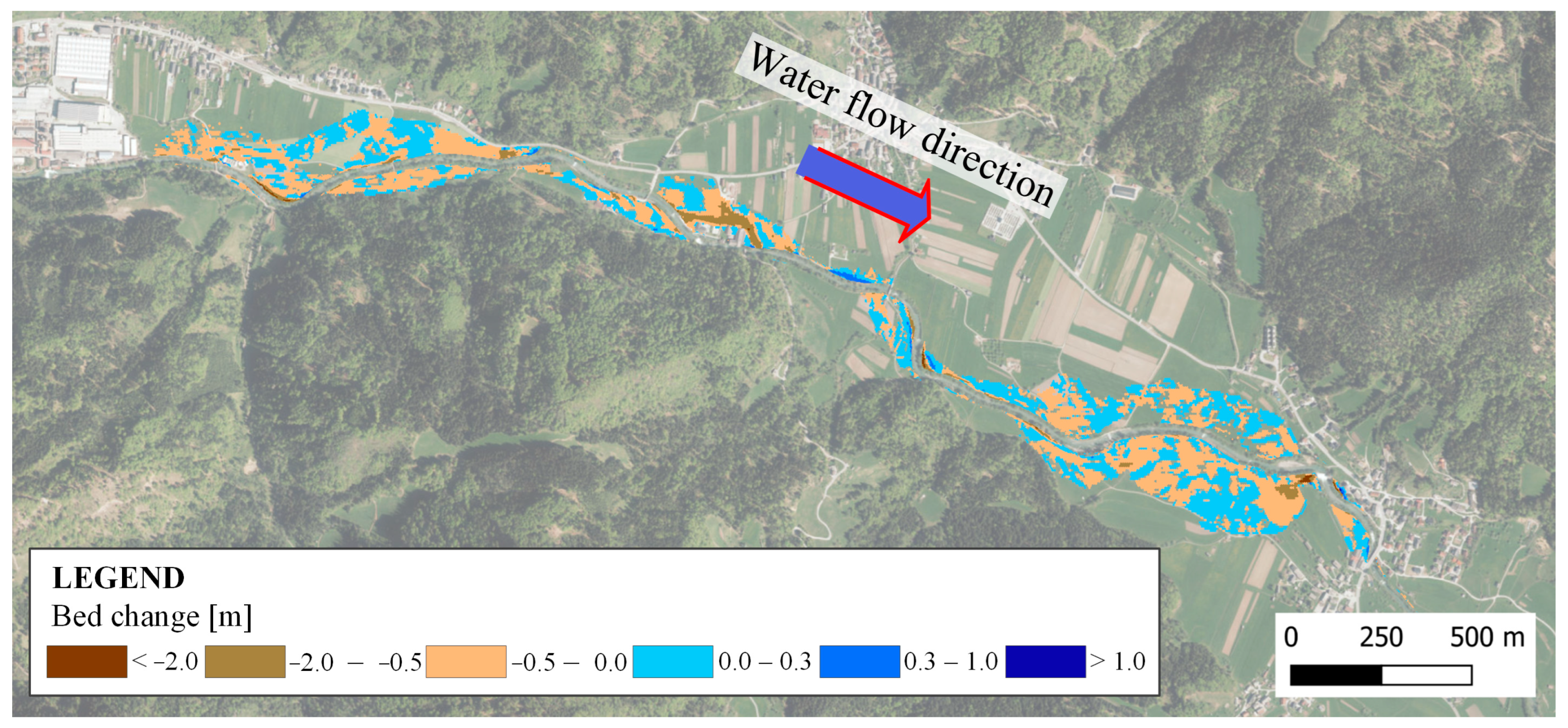
The obtained modelling results can be presented using spatial maps, including bed characteristics and sediment transport. Bed-related results include changes in terrain caused by erosion and deposition, bed elevation, and grain-size composition. Transport-related results include shear stresses and their critical values, sediment concentrations, and transported volumes. For this study, we primarily focused on erosion and deposition, represented by the ‘bed change’ layer, which indicates cumulative surface changes in meters. The map legend was adapted so that erosion (negative values) is shown in brown and deposition (positive values) in blue, with classification thresholds aligned to official erosion hazard maps: erosion up to −0.5 m, −0.5 to −2 m, and greater than −2 m, and deposition up to 0.3 m, 0.3–1 m, and greater than 1 m (
Figure 4).
Except for peripheral zones where floodwater velocities remain low (<0.5 m/s), bed-level changes occur across nearly all inundated areas. Most erosion and deposition values fall between −0.5 and 0.3 m. More substantial erosion is concentrated near the main channel, where flow velocities reach 1.5–2 m/s, and in areas where floodwaters are redirected back into the river due to terrain obstacles, such as upstream of the weir in the village of Dolenja vas. Additional deepening occurs where topography channels flow across the floodplain, generating locally higher velocities. Conversely, deposition dominates where velocities decrease, typically with sediment layers less than 0.5 m thick but locally exceeding 1 m. Based on land use classification, meadows and croplands are most affected. On the contrary, the modelling results incorrectly suggest significant erosion in built-up areas. This is likely the consequence of the sediment transport parameterization. Built-up surfaces are assigned lower Manning’s roughness coefficients, resulting in higher flow velocities and thus unrealistically overestimated erosion capacity. In the real world, high velocities between buildings are very likely, but they occur due to constrictions and irregular flow patterns rather than low surface roughness.
3.2. Scenarios with Increased/Decreased Values of Manning’s Roughness Coefficients
In the scenarios with values of the Manning’s roughness coefficients reduced by 10% and 20%, only a minimal decrease in flood extent was observed, and the overall impact was not significant. The maximum reduction in the flood boundary extent was about 1.7 m for the −10% scenario and 2.5 m for the −20% scenario. Flow velocities on floodplains slightly increased due to lower roughness coefficients. Compared to the baseline scenario, regions with velocities greater than 1 m/s increased in extent, although their spatial positions remained largely consistent. Consequently, water drained more quickly from the inundated areas, leading to water-level reductions of up to 5 cm (−10% scenario) and 7 cm (−20% scenario).
Higher velocities also influenced sediment transport and changes in bed level. Increased velocities primarily resulted in greater erosion, although most values remained within a range of −0.5 m. However, areas where the bed had already deepened by more than −0.5 m in the baseline scenario expanded and deepened further with decreasing roughness coefficients. The eroded material was redeposited on the floodplains further downstream. As erosion intensified, the volume of deposited sediment also increased, although deposition heights remained similar to those in the baseline scenario, typically ranging up to 0.3 m (
Figure 5).
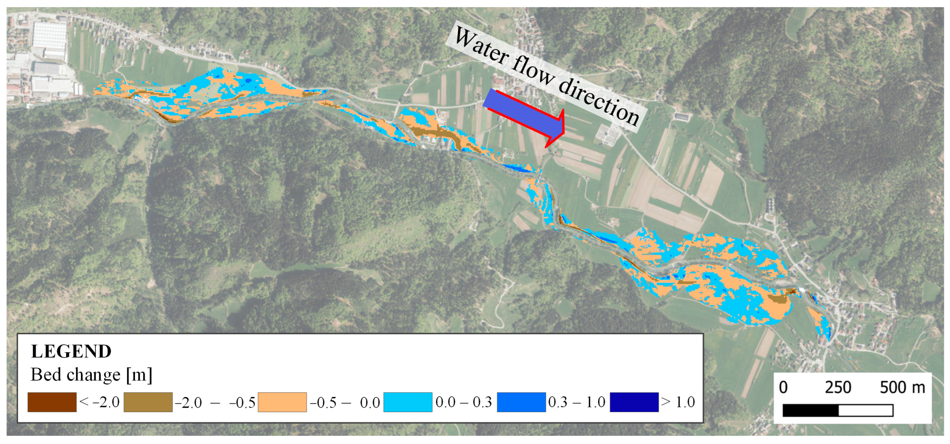
In the scenarios with values of the Manning’s roughness coefficients increased by 10 and 20%, the results were, as expected, opposite to those observed with reduced coefficients. The floodplain extent increased slightly, up to 2 m in the +10% scenario and up to 3 m in the +20% scenario. Higher roughness values for each land use category led to lower flow velocities on the floodplains. Areas with velocities exceeding 1 m/s decreased in size. Lower velocities caused water to remain longer on the floodplains, resulting in slightly higher water levels (up to 3 cm in the +10% scenario and up to 6 cm in the +20% scenario).
Higher roughness reduced flow velocities across inundated areas, which in turn decreased shear stresses affecting sediment transport. Consequently, erosion was less extensive and shallower, generally remaining within a depth of −0.5 m. With less eroded material, sediment deposition also decreased. Deposited sediments caused slight increases in surface elevation, up to 0.3 m, with larger deposits occurring only in depressions or areas with strong negative velocity gradients (
Figure 6).
Table 4 presents the areas falling within each bed change class for all the tested scenarios. The results show that by increasing Manning’s roughness coefficients, the areas prone to severe erosion (greater than −0.5 m) are mainly decreasing, while they are increasing for the moderate erosion (between −0.5 m and 0 m). For moderate deposition (0–0.5 m), we obtained the largest areas for the baseline scenario. Increasing Manning’s roughness coefficients, the areas prone to severe deposition (greater than 0.3 m) are again decreasing.
3.3. Bed-Level Changes in Floodplains
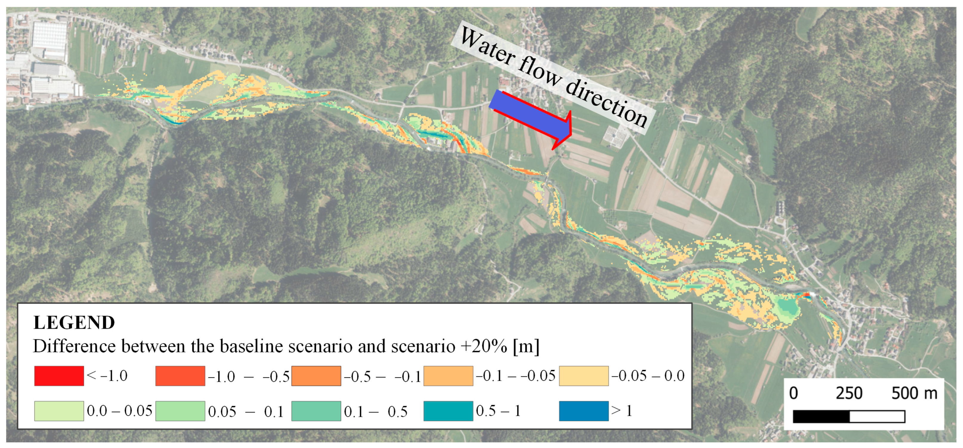
To assess the effects of decreasing and increasing floodplain roughness, raster maps of bed-level changes (“bed change” layer) at the end of the simulation were exported and compared using the GIS tools. For scenarios with reduced values of the Manning’s coefficients, differences were calculated relative to the baseline scenario. Negative values (yellow to red) indicate increased erosion due to lower roughness, while positive values (green) show areas with greater deposition (
Figure 7). Conversely, for scenarios with increased roughness, positive values indicate reduced erosion, and negative values indicate reduced deposition (
Figure 8).
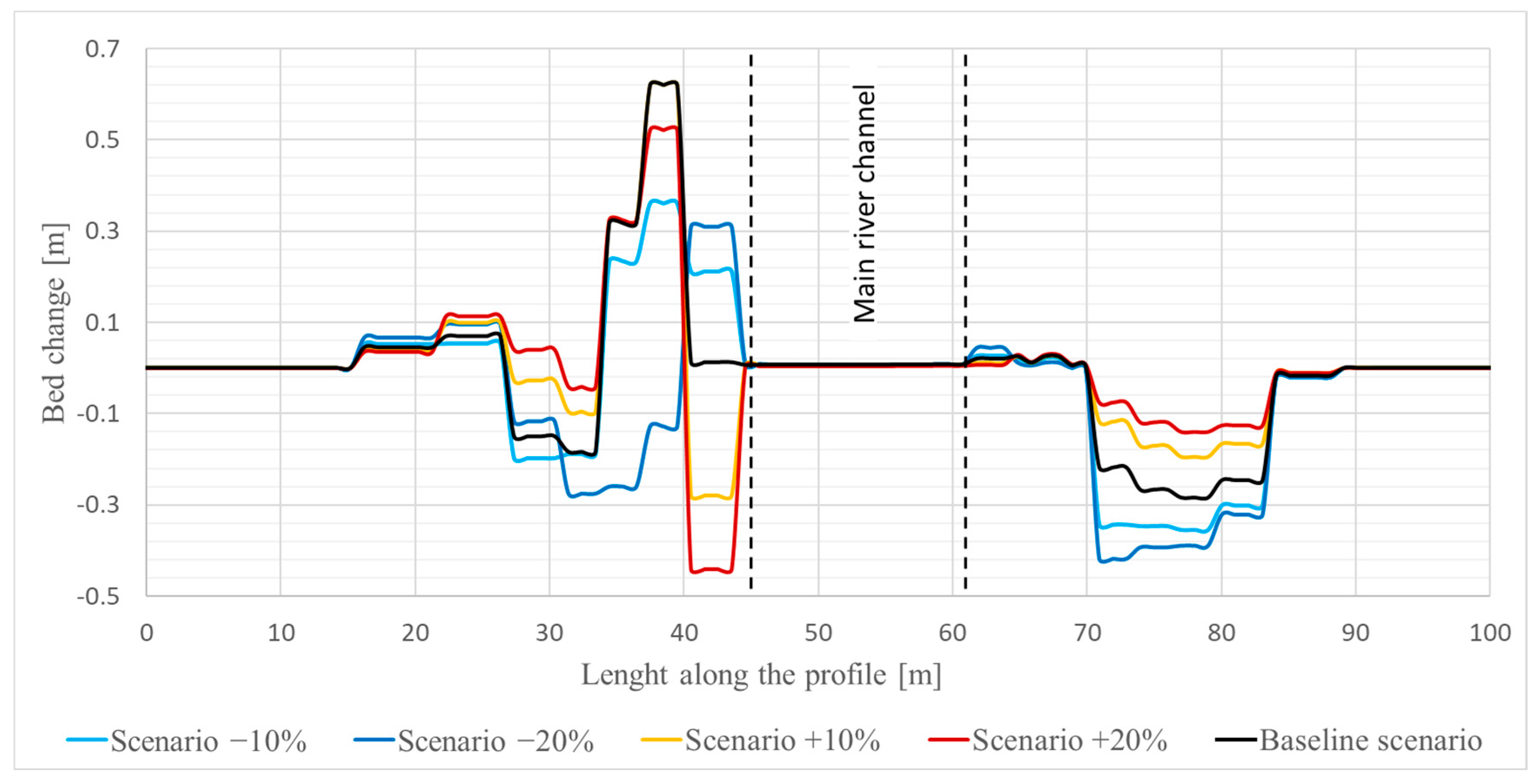
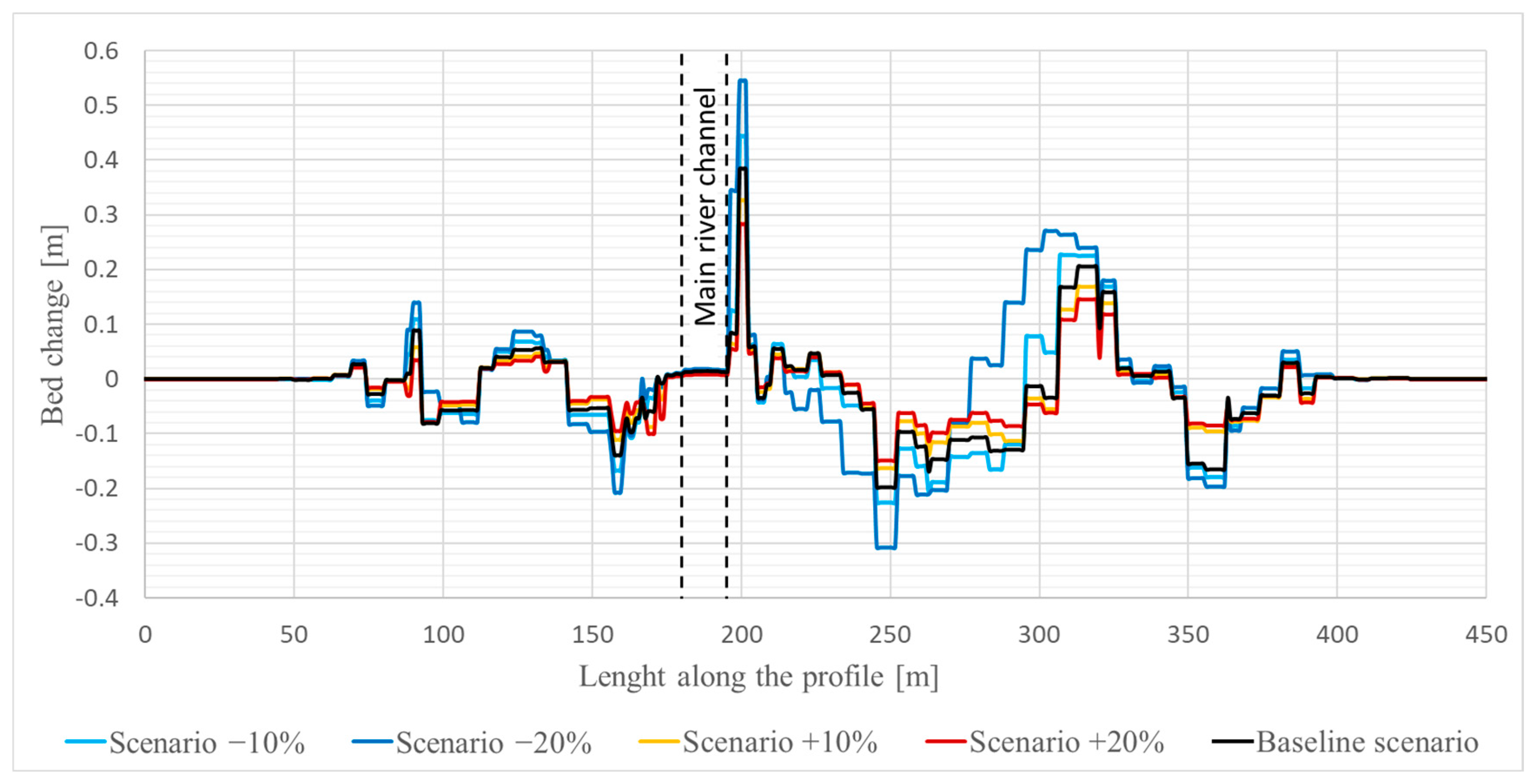
Additionally, bed changes were analyzed in two cross-sections: an upstream section (P1) in a narrow part of the valley between settlements of Studeno and Selce, and a downstream section (P2) at the widest flooded area, upstream of the weir in Dolenja vas (
Figure 1).
Since the main channel was considered non-erodible, bed elevations in the main channel remained unchanged in P1. At the same time, minor downstream sediment depositions occurred, with bed elevation increases ranging from 1 cm (20% roughness increase) to 2 cm (20% roughness decrease).
In P1, the most significant changes occurred in two areas: deposition on left-bank floodplains (0.35–0.6 m thick) and intensified erosion on right-bank areas, where secondary concentrated flow exceeded 1–1.5 m/s (
Figure 9). In contrast, in P2, the most significant changes occurred on the right floodplain, where topography created zones of varying flow velocities and strong gradients, resulting in both erosion and deposition (
Figure 10). Under the −20% scenario, up to 0.3 m of material was eroded, while under the +20% scenario, erosion was only 0.15 m. The highest deposition occurred in overgrown agricultural areas on the right river bank, reaching 0.55 m (−20% scenario) and 0.28 m (+20% scenario) due to lower and higher velocities, respectively.
Overall, bed-level change maps confirm that the maximum sediment transport occurs under reduced roughness (−20%), while increased roughness (+20%) limits sediment movement. Negative bed-change values indicate net erosion, showing that sediment is transported downstream along the Selška Sora floodplains. The results highlight how variations in values of the Manning’s coefficients can significantly influence both the magnitude and spatial distribution of erosion and deposition on floodplains, particularly in areas with concentrated flow or low roughness.
3.4. Flood and Erosion Hazard Maps
Based on the hydraulic and sediment transport simulations, flood and erosion hazard maps were created to visualize areas of potential erosion and deposition under the Q100 flood scenario, which was one of the study’s main objectives. These maps translate modelled bed-level changes and sediment movement into practical spatial information, using threshold values for material removed or deposited to classify low, medium, and high erosion hazard. Classification was conducted in accordance with Slovenian legislation [
9].
In the graphical interface RAS Mapper, threshold values for depths, extents, and velocities at Q100, together with eroded or deposited material, were defined for each scenario. For erosion, thresholds were set at −0.5 m and −2 m, and for deposition at 0.3 m and 1 m. Polygons based on these thresholds were exported as .shp files, converted to .dxf in QGIS, and compiled in ZWCAD [
43] to produce the final flood and erosion hazard maps.
Two types of erosion hazard maps were created, one for eroded material and the other for deposited material.
Erosion maps show areas with potential material loss of up to 0.5 m, between 0.5 and 2 m, and over 2 m. Most floodplains are subject to minor erosion (≤0.5 m), while areas with concentrated flow and low roughness may experience 0.5–2 m of erosion. In a few locations near the riverbanks, erosion can exceed 2 m, where water overtops or returns from the floodplain into the main channel.
Deposition is common in areas where the flow slows down and sediments settle, forming layers up to 0.3 m in thickness. Occasionally, these values are exceeded to 0.3–1 m. Very few areas experience deposition exceeding 1 m. Sediments eroded from the floodplains are transported downstream and deposited in the channel or on the other floodplain areas.
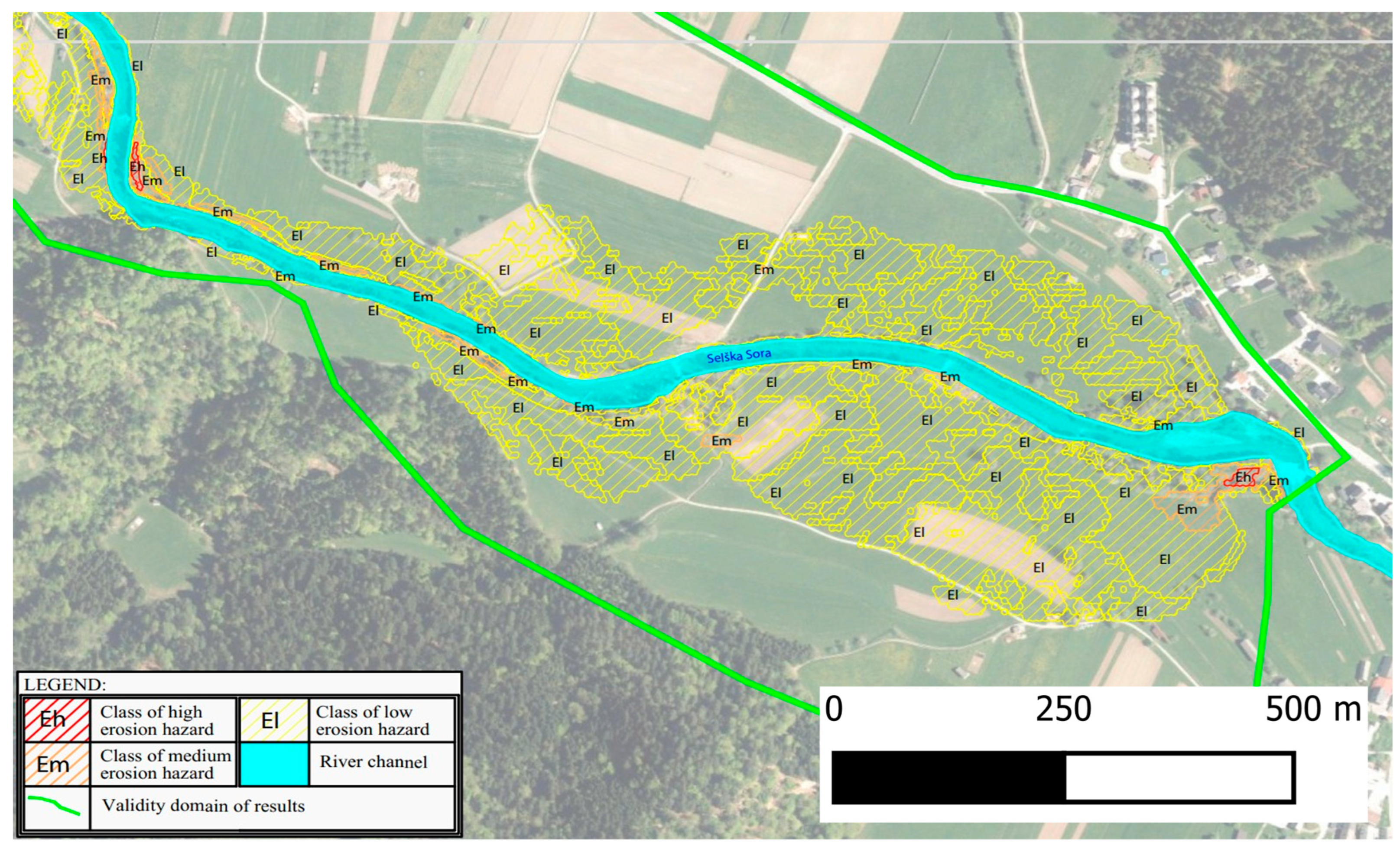
Erosion hazard classes were defined by combining erosion and deposition layers. According to regulations, three classes were defined: low (El), medium (Em), and high (Eh) hazard. Most areas fall into the low class (El), corresponding to erosion lower than 0.5 m or deposition lower than 0.3 m. Medium hazard areas (Em) correspond to erosion of 0.5–2 m or deposition of 0.3–1 m, while a few locations with erosion greater than 2 m or deposition greater than 1 m are classified as high hazard (Eh).
Figure 11 presents an example of the erosion hazard map for the section of the Selška Sora River (for the baseline scenario), and
Table 5 provides information on the areas falling within each erosion hazard class for all the tested scenarios, together with the % deviation from the baseline scenario. The results indicate that by changing Manning’s roughness coefficients, fewer areas are classified under the low and more under the high erosion hazard class. The extent of the medium hazard class is decreasing by increasing Manning’s roughness coefficient.
3.5. Limitations of the Proposed Approach
Hydraulic limitations in HEC-RAS sediment transport modelling stem from simplifications in how the software represents flow, which, in turn, affects the accuracy of erosion and deposition predictions. Because HEC-RAS uses depth-averaged shallow-water equations, it cannot capture detailed three-dimensional flow structures such as secondary currents, turbulence near banks, or eddies around structures, which present forces/processes that drive the sediment movement. Limited turbulence representation reduces the accuracy of suspended sediment concentration profiles, while feedback between morphologic change and hydraulics is updated only at coarse intervals.
Shear stress, a key driver of sediment mobility, is estimated using simplified relationships that rely on fixed roughness values and do not respond dynamically to evolving bed conditions or changes in grain size.
Grid resolution and inappropriate refinement limit the model’s ability to resolve sharp velocity gradients, channel curvature effects, and small-scale morphologies, such as bars or scour holes.
The 2D sediment transport module in HEC-RAS is relatively new and thus prone to computational instability. Moreover, the additional input requirements (e.g., geological and sediment data) and extended computational times increase both the cost and complexity of such analyses.
The constraints mentioned above indicate that HEC-RAS is best suited for reach-scale sediment routing and long-term trends, rather than fine-scale morphodynamics or detailed scour prediction.
Significant limitations also arise from the lack of detailed input data, including the magnitude and grain-size distribution of sediment inflow from upstream reaches, its temporal variability during high-flow events (for which measurements are scarce and often unreliable), the spatial heterogeneity of grain-size distribution on floodplains (boreholes for detail geotechnical analysis are typically available only in small numbers, offer low spatial resolution, or are absent, consequently, general soil database maps with low spatial resolution are often used), the degree of root-system development, the length of the growing season, vegetation resistance, and the overall effectiveness of vegetation in providing erosion protection. Without sediment monitoring data, model calibration and validation are challenging.
4. Conclusions
This study demonstrates the potential of applying a 2D hydraulic sediment transport model for assessing erosion hazards in line with Slovenian legislation, using the Selška Sora River as a case study. Compared to traditional (empirical) approaches that often rely on engineering assumptions and field observations, the model enables a more process-based, spatially detailed representation of erosion and deposition dynamics during extreme flood events.
The developed methodology enabled the production of erosion hazard maps, which complement existing flood hazard maps by providing enhanced insight into areas of erosion risk. These maps can help identify areas of increased vulnerability, particularly in floodplains with concentrated flow or low roughness.
According to our results, in the case study area, 21.9 out of 300 ha of floodplains are subject to erosion, while 23.9 ha are prone to deposition. Additionally, we obtained information on the areas falling within the low, medium, and high erosion hazard classes, i.e., 43.8 ha, 1.9 ha, and 0.1 ha, respectively.
Further findings indicate that while topography, geology, and hydrological inputs are mainly fixed, land use data and Manning’s roughness coefficients significantly influence the magnitude and spatial distribution of erosion and deposition. Careful calibration and parameter selection are therefore crucial. By systematically varying roughness coefficients, the study demonstrated how different vegetation conditions and parameter uncertainties affect floodplain erosion patterns, offering valuable insights for scenario-based hazard analysis.
To properly acknowledge methodological constraints, it should be noted that the absence of field measurements of erosion and deposition prevented a direct validation of the morphodynamic results. Since the study focused primarily on floodplain processes, the channel was treated as non-erodible, potentially limiting the representation of sediment exchange between the channel and the floodplain. The modelling results are further influenced by uncertainties in sediment characteristics and land use-based roughness parameterization, which may locally over- or under-estimate erosion potential. These limitations highlight the need for future work supported by detailed sediment monitoring, improved sediment and vegetation data, and a more comprehensive representation of channel–floodplain interactions.
The results of our work indicate that a model-based approach for erosion hazard mapping exhibits significant potential. The obtained maps can serve as a valuable tool for spatial planning, flood and erosion risk management, and infrastructure siting. With better sediment data, refined modelling approaches, and ongoing software development, these methods are expected to become increasingly reliable, efficient, and applicable in Slovenia, the EU, and beyond.
