Article

Numerical Simulation of Sloshing Tanks with Shallow Water Model Using Low Numerical Diffusion Schemes and Its Application to Tuned Liquid Dampers

by
Mahdiyar Khanpour
1,*,
Abdolmajid Mohammadian
1,
Hamidreza Shirkhani
1,2 and
Reza Kianoush
3
1
Department of Civil Engineering, University of Ottawa, 161 Louis Pasteur Private, Ottawa, ON K1N 6N5, Canada
2
National Research Council Canada, 1200 Montreal Rd, Ottawa, ON K1A 0R6, Canada
3
Department of Civil Engineering, Toronto Metropolitan University, 350 Victoria Street, Toronto, ON M5B 2K3, Canada
*
Author to whom correspondence should be addressed.
Water 2025, 17(18), 2703; https://doi.org/10.3390/w17182703
Submission received: 6 August 2025 / Revised: 28 August 2025 / Accepted: 7 September 2025 / Published: 12 September 2025
(This article belongs to the Section Hydraulics and Hydrodynamics)

Abstract

The initial part of this study fills a notable research gap by investigating the substantial impact of numerical diffusion errors from different schemes on sloshing tank models. Multiple numerical models were developed: first- and higher-order upwind schemes equipped with precise wall treatment using ghost nodes, MacCormack and central methods that are explicit second-order finite difference methods, and Preissmann and staggered methods employed in full-implicit and semi-implicit modes. Furthermore, the separation of variables technique was proposed for simulating sloshing tanks and deriving an analytical equation for the tank’s natural period. An analytical solution to the perturbation was employed to examine the numerical diffusion of the schemes. Subsequently, two sloshing tests, resonant and near-resonant excitations, were employed to determine the numerical diffusion and calibrate the physical diffusion coefficients, respectively. Finally, an efficient and accurate numerical scheme was applied to a linear shallow water model including physical diffusion and coupled with a single degree of freedom (SDOF), to simulate tuned liquid dampers (TLDs). It shows that the efficiency of TLD is associated with a compact domain around resonance excitation. Contrary to SDOF alone, when SDOF interacts with TLD the impact of structural damping on reducing the response is minimal in resonance excitation.

1. Introduction

Liquid storage tanks have grown significantly over the past few decades and are considered a vital component of industrial infrastructure. These structures are widely used for the storage of a variety of materials, such as oil and gas, liquefied natural gas, chemical fluids, waste in various forms, nuclear materials, and water supply facilities. Under seismic excitation, storage tanks experience fluid movement known as sloshing waves, which generates pressure within the tanks. While sloshing waves can potentially threaten the stability of tanks, they offer significant benefits when employed in tuned liquid dampers (TLDs).
TLDs are sloshing tanks mounted on the roof of structures to reduce vibrations when they undergo lateral dynamic movement. Typically, the natural frequency of a sloshing tank is tuned to match the natural frequency of the structure [1,2,3,4,5]. This alignment results in an amplified response of the sloshing tank, which in turn influences the behavior of the structure. Experimental and numerical studies have shown that when seismic loading closely approaches the structural frequency, known as near-resonance excitation, the sloshing waves significantly reduce the structural vibration [2,3]. This indicates that the tuned liquid damper (TLD) performs optimally under near-resonance excitation, whereas it represents the worst-case scenario for the stability of the structure in the absence of a TLD. Certainly, researchers have explored various aspects of tuned liquid dampers (TLDs) in their studies. For example, in [6] research was conducted into the impact of wave breaking on TLD modeling. The influence of screens and depth ratio on the performance of TLDs was separately investigated in [7,8]. In [9,10], numerical investigations were conducted to examine how the sloped bottom changes the damping effect of TLDs. The primary parts of the TLDs are sloshing tanks and researchers have made significant efforts to model them by applying certain simplifying assumptions. So, the first section of this research focuses on the numerical molding of sloshing tanks.
Former methods rely on the analytical approach in [11], which divides the fluid in moving tanks into convective and impulsive parts. Although this method has many applications in engineering because of its simplicity, it should be acknowledged that this method provides a quite rudimentary approximation of fluid sloshing.
Later, potential flow theory [12,13,14] was applied to sloshing tanks to provide a more accurate picture of fluid movement. However, most of these models assume linear and small-amplitude waves.
Other researchers have employed more advanced methods, such as volume of fluid (VOF) [15,16,17] and smoothed particle hydrodynamics (SPH) [18,19] to model sloshing tanks. Although these models are capable of generating more accurate and detailed results, they suffer from high computational costs and noisy solutions [20].
Shallow water models are hyperbolic equations based on depth-averaged Euler equations [21] that can be used for modeling sloshing tanks. The literature review indicates that a few studies used shallow water models for sloshing tank simulations [22], and most of them were applied to simulate sloshing tanks in TLDs [2,3,6,23]. Each of these models has merits and disadvantages. Shallow water models that benefit from low-cost calculations and decent accuracy, appear to be an appropriate tool for modeling TLDs.
Although some studies have focused on the application of shallow water models to sloshing tanks, there is a gap in how the temporal and spatial discretization schemes using numerical models influence the accuracy of the modeling of sloshing tanks. One of the primary objectives of this study is to evaluate the performance of various schemes utilized in simulation of sloshing tanks, and to propose efficient and accurate numerical methods for such applications. The focus of this study will be on linear shallow water equations, which is an extremely fast system with a low computational cost. Such a low-cost numerical solution is particularly useful for tank optimization purposes where many simulations are demanded. First, upwind schemes [24,25], that approximate the advection term with respect to the flow direction, were investigated. The simplest upwind scheme is the first-order scheme, which can be enhanced by higher-order upwind methods, such as κ schemes, that rely on more data points for flux approximation. In addition, a solution is proposed in this study to model wall boundaries with less numerical diffusion error. Subsequently, the MacCormack method and the central scheme, which are second-order explicit finite-difference schemes, were studied. MacCormack, a type of finite difference scheme introduced in [26], was first used as a solution to compressible Navier–Stokes equations. Then, it was applied in [27] and subsequently developed in [28] for water hammer analysis. Furthermore, refs. [29,30] utilized this method for unsteady free-surface flows. For implicit and semi-implicit methods, two efficient second-order schemes were discussed: (i) Preissmann [31] and (ii) Staggered methods [21]. In open-channel hydraulics, the Preissmann scheme [32] has been extensively employed [33,34]. It was stated in [35] that the scheme is flexible and appropriate for hyperbolic equations. The Preissmann scheme has also been applied to simulate flood wave propagation and unsteady flows in channel networks [36,37]. It has also been used to solve the Hairsine–Rose erosion equations [38]. This scheme solves both the continuity and momentum equations at the control volume of each node. Although the early use of staggered implicit and semi-implicit schemes was relevant to viscous compressible flows [39], a scheme for shallow-water equations was later proposed in [40]. A staggered method, unlike the Preissman scheme, provides a continuity control volume at one node and a momentum control volume at a subsequent node. This results in the velocity grid being non-overlapping downstream of the wave height grid. Furthermore, a separation of variables approach was proposed in this study to model the sloshing process. Different disciplines have used this technique to solve partial differential equations, such as the dynamics of continuous systems [41] and wave modeling [42]. This technique relies on the assumption that the solution to the partial differential equation can be separated into the product of several functions. Each function depends only on a single independent variable. In current research, the separation variable technique was not only applied to model sloshing tanks but was also utilized within linear shallow water equations to derive an analytical expression for the natural period of the tank. When comparing this expression with another commonly used and reliable formula found in the literature, it revealed a range of water depth to tank length ratios that yield accurate results for the natural period of the tank.
To verify the accuracy and evaluate numerical diffusion error associated with the above-mentioned schemes in the present research, an analytical solution to a perturbation test and experimental data associated with resonant sloshing were employed. After verification, more accurate numerical schemes with reduced numerical diffusion errors were identified. Following that, a method benefits from a cost-effective computation and negligible numerical diffusion errors was incorporated with a physical diffusion term, whose coefficient was calibrated with experimental data. In the next step, this developed model was coupled with a dynamic equation of a single degree of freedom to model the TLDs. Subsequently, the influence of two parameters, (1) frequency ratio (excitation force frequency/natural TLD frequency) and (2) damping ratio (damping constant/critical damping constant [41]) on TLD performance were investigated.
The remainder of this paper is organized as follows. Section 2 outlines the methodology, including the governing equations. Additionally, it elaborates on the process of coupling these equations to create a TLD model. Section 3 describes several numerical methods for solving the governing equations, and most of the equations are presented in Appendix A. Section 4 addresses four test cases where the impact of numerical methods is compared to analytical solutions or experimental data. In addition, a parametric study of TLD is performed in this part. The concluding remarks complete the study in Section 5.

2. Methodology

The linear shallow water equations for a one-dimensional rectangular tank with length L and averaged depth H (see Figure 1) subjected to acceleration a x can be written as follows:
U t + F x = R
with
U = η u      F = H u g η      R = 0 a x + α D 2 u x 2
In this equation U is variable vector, and F is flux vector as well as R is source vector. Also, u is the depth-averaged velocity, g is the gravitational acceleration, and η is the wave height relative to averaged depth. In the source term, a x refers to the tank acceleration and D is the coefficient of physical diffusion. Also, α is the contribution coefficient of physical diffusion. Section 4.1 and Section 4.2 focus on the numerical diffusion associated with the above-mentioned numerical schemes in the case of both initial perturbation and sloshing, respectively. As a result, to identify numerical diffusion error, physical diffusion was not contributed so α = 0 . However, following that, in Section 4.3, physical diffusion is incorporated into the model to capture more accurate and realistic solution, i.e., α = 1 . Note that for a stagnant tank the vector R is zero.
Two wall boundary conditions were applied: zero velocity and zero wave height gradient.
A non-conservative form of Equation (1) utilized in upwind schemes is expressed in Equation (2).
U t + A U x = R
with
U = η u      A = 0     H g     0      R = 0 a x + α D 2 u x 2
Section 4.4 combines the shallow water model defined by Equation (1) with the dynamic equation of a single degree of freedom (SDOF) system to create a model for a Tuned Liquid Damper (TLD). This portion of the study utilizes a single degree of freedom (SDOF) characterized by dynamic attributes like mass (m), stiffness (k), and damping coefficient (c), situated beneath the sloshing tank as illustrated in Figure 2.
The dynamic response of an SDOF is obtained from Equation (3), in which u s ( t ) is the displacement, u ˙ s ( t ) is the velocity, and u ¨ s ( t ) refers to the acceleration of the SDOF. In addition, F(t) is seismic force excitation and G ( t ) denotes the water tank sloshing force. Here, the finite difference model is applied to discretize dynamic Equation (3) [43].
m u ¨ s ( t ) + c u ˙ s ( t ) + k u s ( t ) = F ( t ) + G ( t )
To couple the system of Equations (1) and (3), the acceleration of sloshing tank, a x in Equation (1), is set equal to the acceleration of the SDOF, u ¨ s in Equation (3). In addition, besides the seismic excitation force, F ( t ) , the SDOF is influenced by sloshing force, G ( t ) . The sloshing force is determined from the difference in hydrostatic force on the tank walls at x = 0 and x = L in the shallow-water model. This coupled model involves an iterative procedure in each time step to reach convergence for sloshing force. Figure 3 illustrates the flowchart of the developed numerical model for coupling an SDOF to a sloshing tank. Under the shallow water modeling (SWM) module, all of the discussed numerical schemes can be implemented, including upwind methods, the MacCormack method, semi-implicit methods, and separation of variables.

3. Numerical Methods

3.1. Upwind Schemes

A numerical solution to the system of partial differential Equation (1) necessitates both a spatial and a temporal discretization described subsequently.

3.1.1. Temporal Discretization

Four methods for discretizing temporal terms U t were examined: 1—first-order Euler; 2—midpoint; 3—third order Total Variation Diminishing (TVD); and 4—fourth order Runge–Kutta methods. The third and fourth schemes yielded approximately the same and more accurate results. Here, the third scheme (TVD), Equation (A1), proposed in [44], was used because of its lower computational cost than the fourth-order Runge–Kutta.

3.1.2. Spatial Discretization

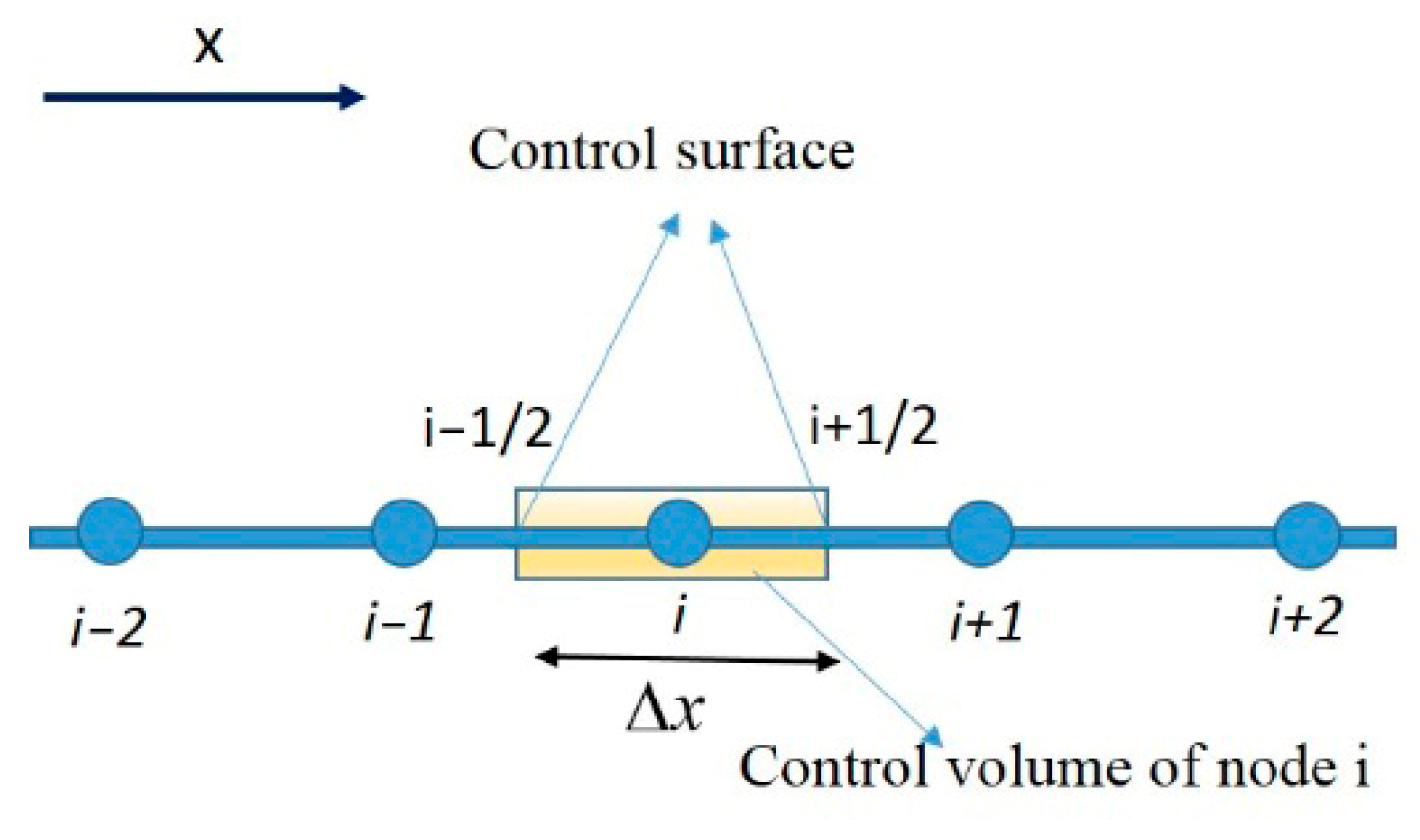
With respect to the control volume of node j shown in Figure 4, the term F x can be determined using Equation (4).
F x = F j + 1 / 2 F j 1 / 2 Δ x
There are a variety of approaches for obtaining F j + 1 / 2 and F j 1 / 2 at the control surface, which is called flux approximation.
To evaluate the flux at the interface in upwind schemes, matrix A should be determined. This matrix relies upon the eigenvalues and eigenvectors of matrix A in the nonconservative form of the shallow water Equation (2). Appendix A provides Equations (A2) and (A3) for calculating matrix A .
First-Order Upwind
According to the first-order upwind scheme, the flux is calculated using Equation (A4) in Appendix A. This scheme approximates the flux using two nodes near the control surface, with a high contribution from an upstream node. The first-order upwind scheme is stable but leads to a high level of numerical diffusion.
Higher-Order Upwind
In this method, which includes a family of schemes known as the κ method, the numerical flux is calculated using the relations (A5), (A6) and (A7) in Appendix A. In this study, the choice of κ is 1/3, which is equivalent to third-order upwind. In addition, a slope limiter, S, was employed to reduce oscillations [24]. In this scheme, the flux approximation at each control surface was determined from the values of the two nearest upstream and downstream nodes.
To remedy the lack of neighborhood nodes near the boundary (nodes 2 and n − 1 in Figure 5), two strategies can be implemented. The first approach uses a first-order upwind scheme for nodes 2 and N − 1. In the second solution, ghost nodes (nodes 0 and n + 1 in Figure 5) are provided outside the domain near the boundary nodes (1 and N), whose specifications are derived from a zero-gradient condition.

3.2. MacCormack Method

This scheme is a predictor-corrector method in which backward differences are employed in the predictor step, and forward differences are used in the corrector step [28]. In the second alternative, forward and backward differences can be applied to predictors and correctors, respectively. Equation (A8) in Appendix A illustrates the application of this scheme to the discretization of a non-conservative shallow water Equation (2).

3.3. Central Difference in Time and Space

In this method for discretization in space and time, the central difference and midpoint are utilized, respectively, to reach second-order approaches. When this scheme is utilized for the non-conservative shallow water Equation (2), Equation (A9) is provided in Appendix A.

3.4. Implicit and Semi-Implicit Method

The main difference between implicit and explicit schemes for Equation (1), the pure advection equation, is that implicit schemes evaluate the term F x at time n + 1, which is unknown. Therefore, this approach yields coupled equations.

3.4.1. Preissmann Method

This scheme proposes the second-order approximation presented in Equation (A10) to discretize the temporal and spatial derivatives [31]. Expression (A11) is developed when this scheme is employed to discretize the shallow water equation. Both the fully implicit and semi-implicit schemes can be obtained using this numerical method.
Considering the velocity and wave height as unknown parameters, 2N unknowns exist for N nodes in the flow domain (see Figure 6). This scheme establishes 2N − 2 equations using discretized equations. Regarding two extra zero velocity equations at the wall boundaries, a matrix equation (Equation (5)) is derived in which A is the coefficient matrix, X is the unknown vector, and B is the known vector updated in each time step. A is a band matrix with four non-zero elements in each row.
A 2 N 2 N X 2 N 1 = B 2 N 1
As an illustration, this matrix equation for N = 4 is shown in Equation (A12) in Appendix A.

3.4.2. Staggered Method

The main difference between this scheme and the Priessmann method is that the unknown parameters u and η are not stored on the same node in this scheme (see Figure 7). The staggered scheme employs two different control volumes for the continuity (mass cell) and momentum (momentum cell) equations. A benefit of this method is that the flux values are derived directly from the variables stored on the surface of the control volume. Therefore, flux approximation methods are not required. This method defines the time and space derivative operations based on Equation (A13) in Appendix A. In Appendix A, expression (A14) demonstrates how Equation (1) can be discretized using this scheme.
Consider 2N − 1 nodes in the flow domain, as shown in Figure 7. In this case, the number of unknowns is 2N − 1. Meanwhile, the number of equations based on expression (A14) in Appendix A is equal to 2N − 3. Introducing zero velocity as the wall boundary condition results in the same number of unknowns and equations. Hence, matrix Equation (6) is developed, in which A is the coefficient matrix, X is the unknown vector, and B is the known vector. Although the coefficient matrix was constant, the known vector was updated at each time step.
A ( 2 N 1 ) ( 2 N 1 ) X ( 2 N 1 ) 1 = B ( 2 N 1 ) 1
Equation (A15) in Appendix A shows the matrix equation for N = 4. Matrix A is a band matrix with three nonzero elements; therefore, this method requires fewer computations than the Preissmann method.

3.5. Separation of Variables Scheme

In this step, a technique known as the separation of variables method is proposed and will be applied to obtain a solution to the sloshing problem. In this method, it is assumed that unknown variables, velocity and wave height here, depending on space and time can be expressed as the product of a function of spatial coordinates and a function of time (Equation (7)). The assumed space function should satisfy the boundary condition of zero velocities at x = 0 and x = L as well as the zero-wave height gradient at x = 0 and x = L. If n, which is known as the number of mode shapes, is greater, a more precise solution is provided.
η = a n ( t ) cos ( n π x L )      u = b n ( t ) sin ( n π x L )
Replacing these variables in Equation (2), Equation (8) is derived.
a ˙ n ( t ) cos ( n π x L ) + H b n ( t ) n π L cos ( n π x L ) = 0 b ˙ n ( t ) sin ( n π x L ) g a n ( t ) n π L sin ( n π x L ) = M n sin ( n π x L ) a M n = 2 ( 1 ) n 1 n π
Because Equation (8) should be satisfied for each x, the following expression is derived for each mode, n.
a ˙ n ( t ) + H b n ( t ) n π L = 0 b ˙ n ( t ) g a n ( t ) n π L = M n a M n = 2 ( 1 ) n 1 n π
Consequently, with the aid of the separation of variables method, partial differential equations are transformed into ordinary differential equations.
Prior to delving into the numerical modeling, the separation of variables method is manipulated to derive an analytical expression for the natural period of tanks, which holds a significant role in sloshing dynamics. This analytical approach establishes a parameter range for H L within which the linear shallow water equations provide accurate predictions for the natural period of tanks. For this purpose, let us examine a stationary tank subjected to a standing wave as an initial perturbation. Using the separation of variables method, the wave height and velocity can be determined based on Equation (10) [45]. This solution satisfies the boundary conditions of zero velocity and zero wave height gradient at the walls located at x = 0 and x = L.
η = n = 1 N a n cos ( n π x L ) cos ( ω n t ) u = n = 1 N b n sin ( n π x L ) sin ( ω n t )
The proposed analytical solution for the wave height and velocity in Equation (10) for n = 1 is converted to Equation (11).
η = a c o s ( π x L ) cos ( ω t ) u = b sin ( π x L ) sin ( ω t )
By replacing u and η , which satisfy the boundary condition, in the linear shallow water equation for a stagnant tank (Equation (1) with vector R = 0), the following expressions can be established:
ω cos ( π x L ) sin ( ω t )      H π L cos ( π x L ) sin ( ω t )   g π L sin ( π x L ) cos ( ω t )      ω sin ( π x L ) cos ( ω t )   a b = 0 0
The left matrix should be singular to obtain a nontrivial solution. With the determinant of the left matrix, the coefficient matrix, equal to zero, Equation (13) can be derived.
ω = π L g H f = g H 2 L
On the other hand, in the literature, many researchers have used the analytical Equation (14) to determine the natural frequency of the water tank.
f = 1 2 π × ( n π g L ) × tanh ( n π H L )
The analytical natural frequency for n = 1 is converted to the following expression
f = 1 2 π × ( π g L ) × tanh ( π H L )
With the assumption of tanh ( π H L ) = ( π H L ) in Equation (15), the following expression is developed for the natural frequency of the tank:
f = g H 2 L
Consequently, when tanh ( π H L ) approaches π H L , the analytical formula provides the same results as the linear shallow water equations (see Equations (13) and (16)). The Tylor series for tanh ( x ) is developed in Equation (17), revealing that it can be approximated by x with a second-order truncation error for small values of x.
tanh ( x ) = x + O ( x 2 )
In Figure 8 diagrams of both y = x and y = tanh ( x ) are presented. From this graph, it can be deduced that tanh ( x ) = x is a good approximation up to about x 0.7 . Consequently, for π H L < = 0.7 or H L < = 0.23 , linear shallow-water equations provide an approximately accurate natural period, which is crucial for the design of sloshing tanks.

4. Test Cases and Results

4.1. Perturbation Test

This test pertains to a stationary tank subjected to a standing wave as the initial condition. In this scenario, as mentioned earlier, the analytical solution is provided by Equation (10) [45].
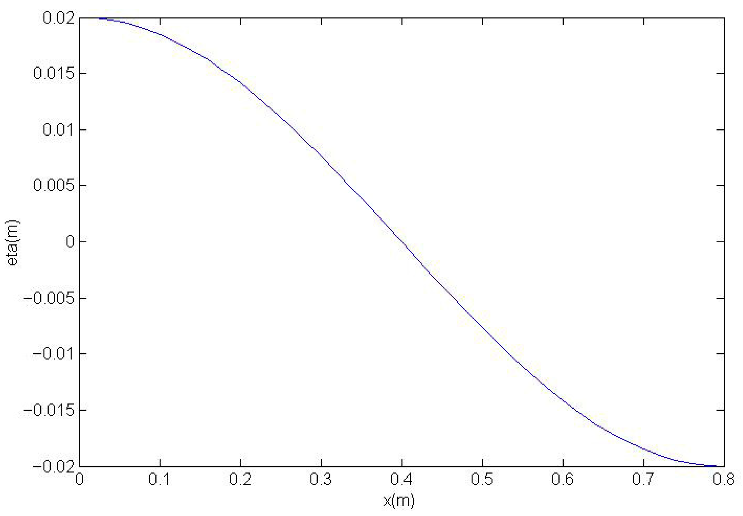
For the case where n = 1, the analytical solution was employed as the initial condition (t = 0) in the shallow water model, as depicted in Equation (18). This initial condition corresponds to a half-cosine wave height, as illustrated in Figure 9.
η = a cos ( π x L ) u = 0
According to the analytical solution for n = 1, Equation (11), and initial condition, the numerical model should generate expression (19) for the free surface at x = L.
η = a cos ( ω t )
In this scenario, where physical diffusion is absent in the shallow water equation, the difference between the numerical model outcomes and the analytical solution is attributed to numerical diffusion errors. The numerical diffusion resulting from the truncation error caused smaller waves in the numerical model. Due to the accumulated error at each time step, this difference grows over time.
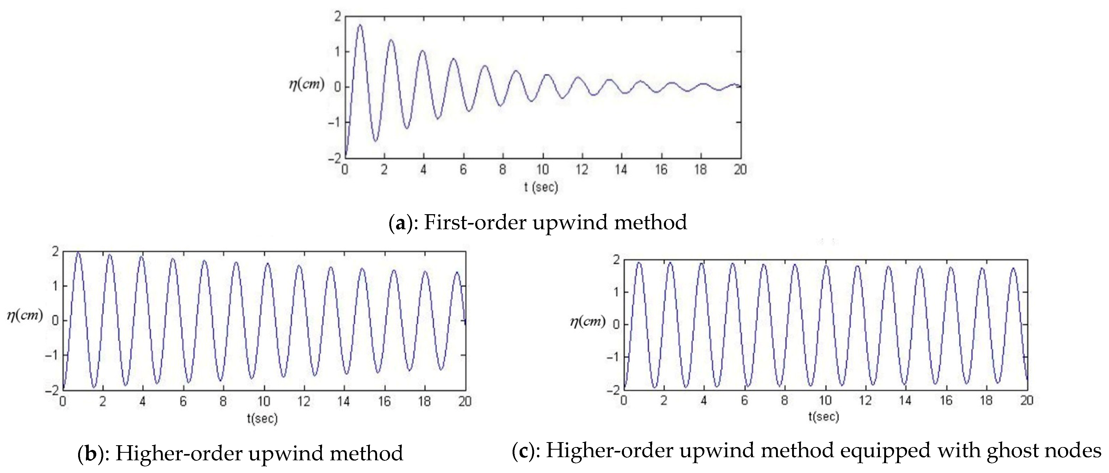
As shown in Figure 10a, the amplitude of the initial perturbation decreased significantly over time predicted by first-order upwind. Thus, the first-order upwind method is associated with high numerical diffusion errors, and the results are inaccurate.
Figure 10b,c show the results of higher-order upwind scheme, indicating low numerical diffusion compared to Figure 10a. As mentioned previously, two alternatives can be employed for the treatment of the wall boundary condition in this scheme. Figure 10b presents the results when the first-order upwind is applied to two nodes near the boundary nodes, and Figure 10c is associated with the application of ghost nodes, as discussed in Section Higher Order upwind. Evidently, the use of ghost particles results in less numerical diffusion and a higher level of accuracy.
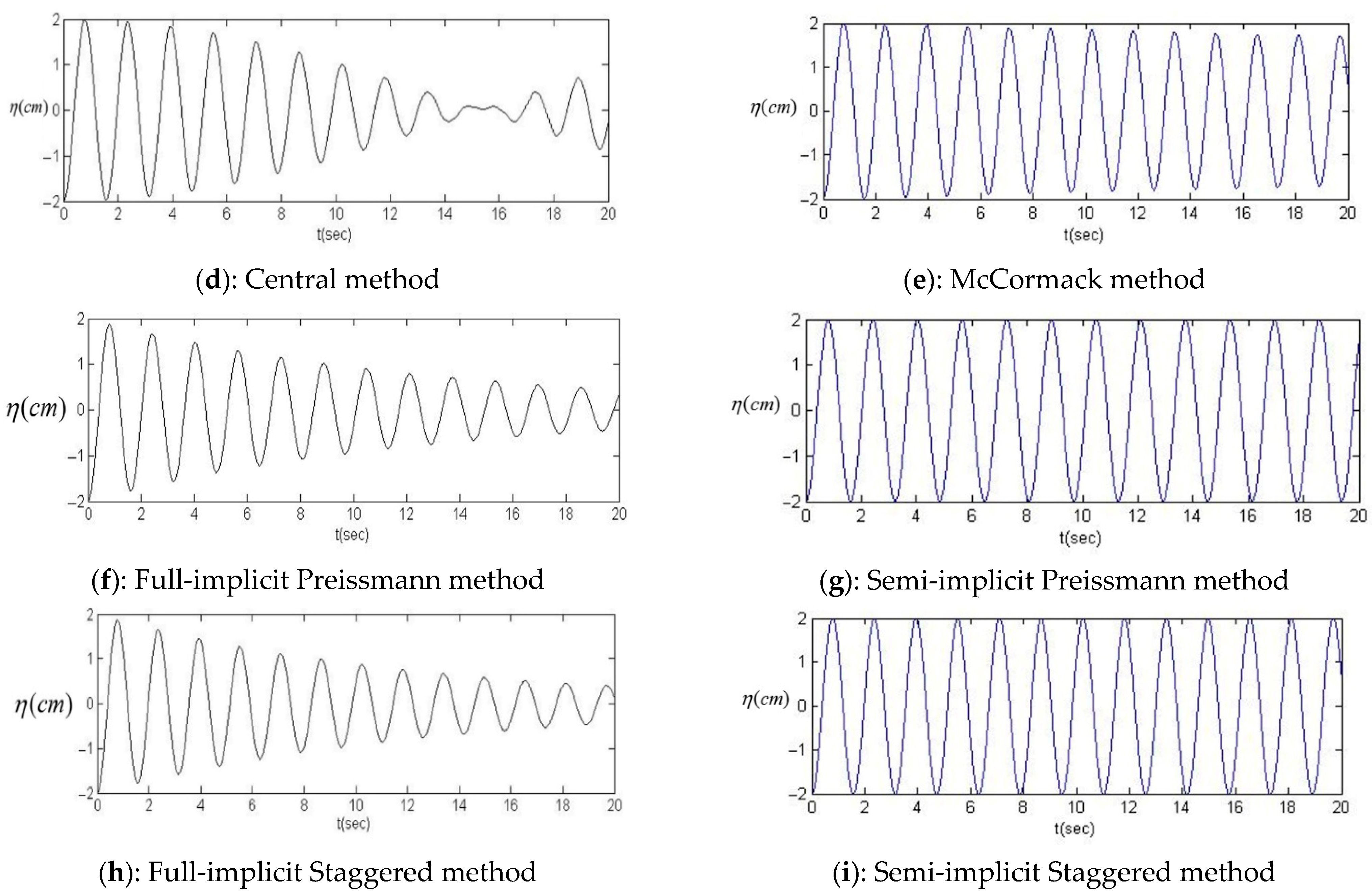
Figure 10d,e reflect the results of the central method and MacCormack scheme, respectively. Although both schemes are explicit and second-order in time and space discretization, MacCormack’s method produces accurate and stable results with negligible numerical diffusion errors. A central method solution, on the other hand, is subject to numerical diffusion and instability. In addition to high accuracy, the MacCormack scheme has lower computational costs than the central method.
The Preissmann method could provide two alternative results: 1—fully implicit; 2—semi-implicit. Figure 10f indicates that the fully implicit method, which is first-order accurate, is accompanied by more numerical diffusion. Conversely, the semi-implicit scheme depicted in Figure 10g, which boasts second-order accuracy, produces highly accurate outcomes while maintaining minimal numerical diffusion errors. Although the semi-implicit method necessitates the solution of matrix equations in each time step, leading to elevated computational expenses, its precision and stability are notably significant.
Figure 10h,i reveal that the staggered method, similar to the Preissmann method, is associated with high-level accuracy for the semi-implicit scheme, whereas it suffers from numerical diffusion error for the fully implicit scheme.

4.2. Sloshing Test

This test was applied to a rectangular tank with a length of L = 0.8 m and an initial water depth of H = 0.1 (see Figure 1), which was subjected to resonant harmonic excitation. The natural frequency of the tank is f = 0.603 H z , with respect to Equation (15). Equation (20) provides the displacement of the excitation, x, with respect to time, t. In this equation a = 0.05 cm is the amplitude of the excitation, and f ¯ is the frequency of the excitation taken to be the same as the natural frequency of the tank to generate resonant harmonic excitation [46].
x = a sin ( 2 π f ¯ t )
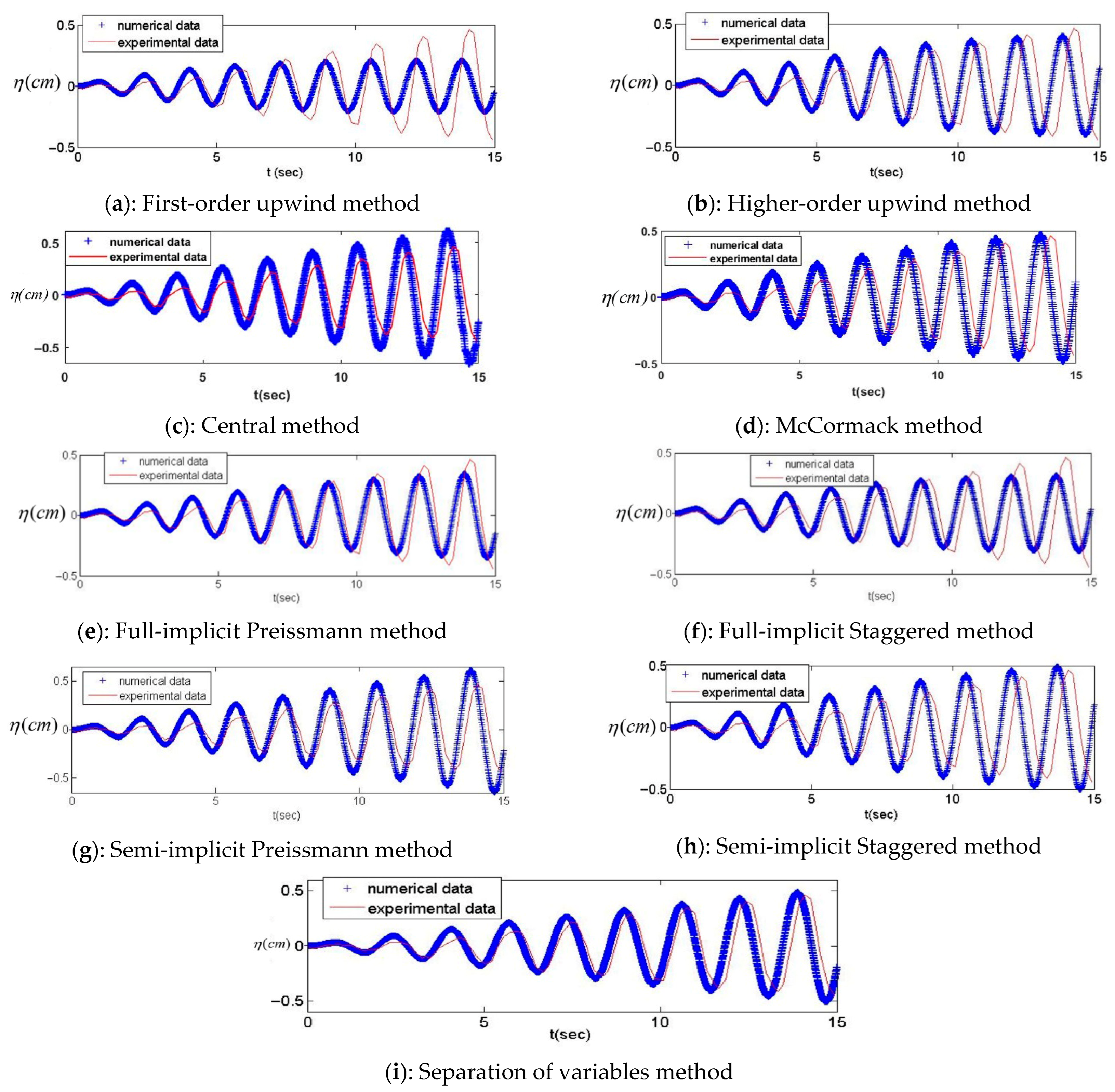
The results of the upwind schemes for this test are presented and compared with the experimental data in Figure 11a,b. The use of first-order upwind causes the prediction of considerably smaller sloshing waves resulting from numerical diffusion, while higher-order upwind provides accurate results.
Figure 11c,d reveal the results of both the Central Methods and MacCormack, accompanied by experimental data. Although both schemes benefit from second-order accuracy, the MacCormack method has a slightly lower computational cost and provides slightly more accurate results. The free-surface profile predicted by MacCormack is smooth, whereas the central method estimates the free surface with a stepped and rough shape (see Figure 12). Hence, as discussed in the previous test, the central scheme tended to be unstable.
In this stage, two implicit schemes (Preissmann and Staggered) were applied to the resonant harmonic excitation. Both schemes experienced slightly smaller sloshing waves when they were adjusted to the full implicit methods (Figure 11e,f). This underestimated prediction of wave height is largely due to the numerical diffusion associated with these schemes, as in previous test. However, for the semi-implicit scheme, as shown in Figure 11g,h, both models overestimated the wave height. Because numerical models are devoid of physical diffusion, which is inherent to the nature of the flow, they predict higher wave sloshing.
The last part of this simulation is dedicated to the numerical solution of the system of ordinary Equation (9) that arises from the separation of variable methods. The present study employed the midpoint method to solve the system of ordinary differential equations. The results indicate that the solution converges at n = 9 and does not change as n increases. The numerical results obtained from this method in the resonance excitation test are compared with the experimental data in Figure 11i. Evidently, this numerical scheme can yield accurate results.

4.3. Physical Diffusion

This verification test used rectangular water tanks with geometric specifications L= 0.966 m and H = 0.119 m. Therefore, with respect to Equation (15), the natural frequency is f = 0.545 Hz. The tank experiences a harmonic near-resonance excitation obtained from formula (21), in which a = 0.259 cm f ¯ = 0.594   Hz and ϕ , the phase angle, is equal to 4 degrees [16].
x = a sin ( 2 π f ¯ t + ϕ )
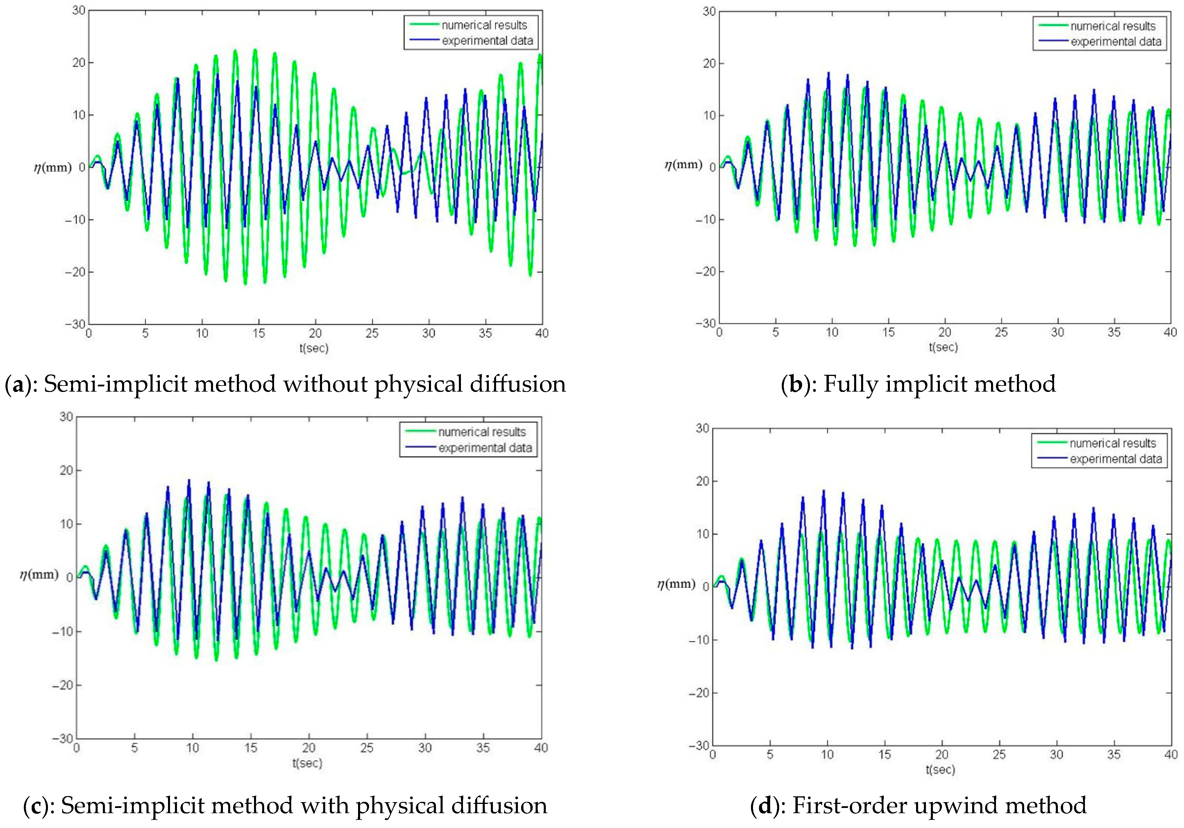
The semi-implicit numerical scheme predicts a higher sloshing wave in Figure 13a due to the lack of physical diffusion. A fully implicit scheme, because of the numerical diffusion error, provides a smaller wave and shows better agreement with the experimental data Figure 13b. To enhance the accuracy of the model, the physical diffusion term D 2 u x 2 was introduced into the momentum equation of a linear shallow water system (1), α = 1 . D is the physical diffusion coefficient.
The equation was solved using numerical schemes with negligible numerical diffusion errors, such as the Preissmann semi-implicit and MacCormack methods. The diffusion coefficient was derived by calibrating the numerical model with experimental data. Figure 13c illustrates the outcome of using a precise scheme when the physical diffusion term is included in the flow equations. With all the assumptions of the linear shallow water equation, this numerical model can predict the trend, period, and peak of sloshing waves in good agreement with the experimental data. On the other hand, the first-order upwind provides a considerably smaller wave high with an approximately uniform pattern, showing a significant deviation from the experimental data Figure 13d.
In addition to the acceptable accuracy of shallow water models when using negligible numerical diffusion schemes, their computational cost is extremely low compared with advanced models such as VOF and SPH. Hence, the model is well suited to the simulation of fluid–structure interactions, which are computationally intensive. In the final step of the present research, a tuned liquid damper (TLD), an example of fluid–structure interaction, was simulated using the proposed model.

4.4. Tuned Liquid Damper Test

In this test, a Single Degree of Freedom (SDOF) system is connected to a sloshing tank, referred to as a Tuned Liquid Damper (TLD), utilizing the partitioned method as elucidated in the Section 2. The coupled system undergoes harmonic excitation force. The dynamic properties of the SDOF and water tank dimensions used in this test are presented in Table 1 [47]. The natural frequency of the SDOF derived from Equation (22) [43] is f s = 0.67   H z , which is equal to the natural frequency of the water tank determined from Equation (15).
f s = 1 2 π k m
Sinusoidal excitation at the same frequency as the SDOF was applied to the structure. Therefore, in this test, the SDOF experienced a harmonic resonance excitation. The numerical response of the SDOF system with and without the TLD is shown in Figure 14a and compared with the experimental results in Figure 14b. In this simulation, the MacCormack method, which takes advantage of less numerical diffusion and computational cost, was used to solve the shallow water equations provided by physical diffusion. Despite the limitations and assumptions of shallow water models and the complexity of TLD simulations, the model equipped with an accurate numerical scheme could generate reasonably accurate results.

4.4.1. The Influence of Frequency Ratio on the Response of the TLD

In this section, the focus is on conducting a parametric study of a Tuned Liquid Damper (TLD) using two key parameters: frequency ratio and damping ratio. The TLD and SDOF systems being studied are described in Table 1. To carry out the study, a harmonic sinusoidal excitation force described in Equation (23) is applied to the SDOF. The force amplitude, A 0 , is tuned to achieve a 1 cm displacement under resonance excitation in the absence of TLD.
F ( t ) = A 0   sin ( 2 π f ¯ t )
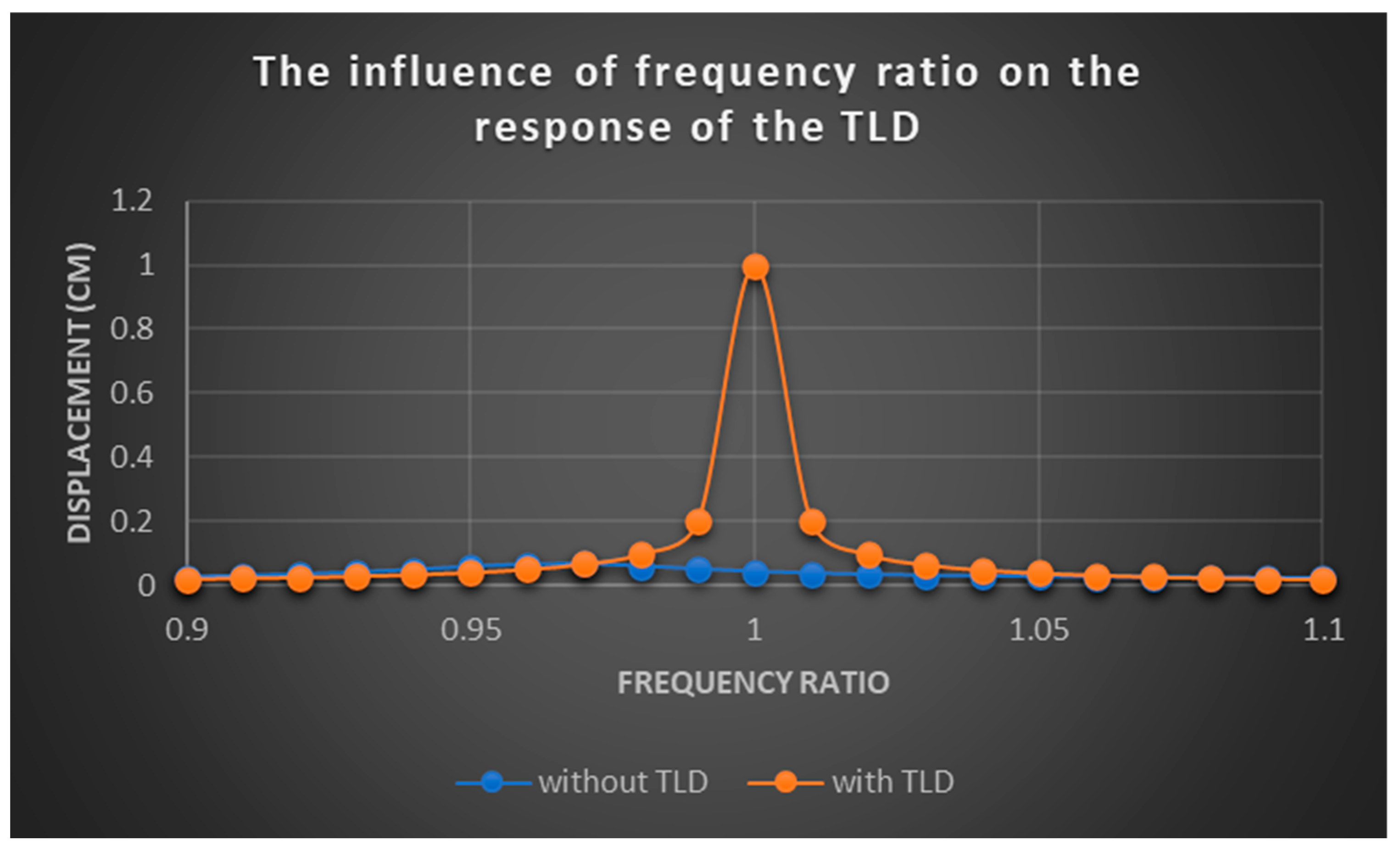
The frequency of the excitation force, f ¯ , is adjusted in such a manner that the frequency ratio ( β ), defined as the excitation force frequency divided by the natural frequency of the SDOF system, falls within the range of 0.9 to 1.1. The simulation results are presented in Figure 15, where the vertical axis represents the amplitude of the SDOF displacement when it reaches a steady-state response. The figure reveals that the TLD has a considerable impact on the response of the SDOF within a narrow range around a frequency ratio of one, referred to as the impact range in this context. In this case study, the impact range is approximately between 0.97 and 1.05. The effect of the SDOF response diminishes significantly as the frequency ratio moves away from one within this impact range. Additionally, it should be noted that the impact range is not entirely symmetric and exhibits a slightly greater extension for frequency ratios greater than one.

4.4.2. The Influence of Damping on the Response of TLD

This section focuses on examining the effect of structural damping on Tuned Liquid Damper performance. The investigation specifically considers resonance excitation, which yields optimal performance of TLDs regarding the impact range discussed in the previous section. The TLD system described in Table 1 is subjected to various damping ratios. Damping ratio, ζ , is determined from Equation (24). In this equation c c is critical damping and equals to 4 π m f .
ζ = c c c
Although critical damping is constant for all simulations, the model utilizes a distinct damping coefficient, c, in each simulation. The damping coefficient varies to generate damping ratios ranging from 0.1% to 1%. For each damping ratio, the SDOF displacement in steady state condition was derived within simulation.
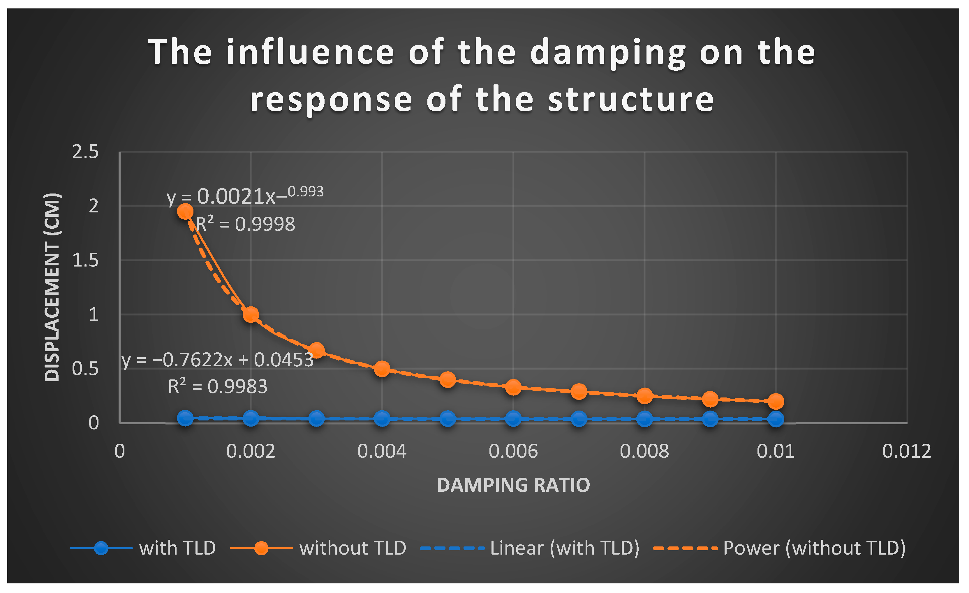
Based on the results presented in Figure 16, it can be observed that in resonance excitation the damping ratio has a significant impact on the Single Degree of Freedom (SDOF) system in the absence of TLD. The data points exhibit a strong correlation, indicated by a high regression coefficient, and can be fitted with a curve described by the u s 1 ζ 0.99 1 ζ . On the other hand, the influence of the damping on the response of the SDOF provided with TLD is not considerable. In this test, as the damping ratio increases, the steady state displacement of the SDOF in resonance excitation reduces with a small slope equal to 0.76. This reduction is insignificant compared to the decrease observed in the SDOF response when the sloshing tank is not present.

5. Discussion

This study addressed the impact of numerical modeling on sloshing tank simulations, filling a significant gap in the literature. The results demonstrated that sloshing predictions are highly sensitive to the choice of numerical scheme. By deliberately omitting physical diffusion from the linear shallow water equation, it was possible to isolate the role of numerical diffusion. The first-order upwind scheme displayed considerable dissipation, while higher-order upwind schemes produced more accurate wave predictions compared with analytical and experimental benchmarks. Additional improvements were achieved by employing ghost nodes at the wall boundaries, which reduced spurious damping. Although both the McCormack and central schemes are formally second-order accurate, the McCormack method provided smoother free-surface profiles and more stable results. Among implicit approaches, semi-implicit formulations such as the Preissmann and Staggered methods showed significantly lower numerical diffusion errors than fully implicit schemes, further confirming the critical influence of discretization techniques on model accuracy. The separation of variables approach, when applied to the linear shallow water equations, also proved highly effective in simulating sloshing tanks. In addition, its application to stagnant tanks undergoing standing waves enabled the derivation of an analytical expression for the natural period, and the study introduced a reliable range of depth-to-length ratios where linear shallow water theory yields accurate predictions.
Building on these findings, the model was extended to include physical diffusion terms calibrated against experimental data. The McCormack scheme, which balances accuracy and efficiency, was then coupled with the dynamics of a Single Degree of Freedom (SDOF) system to develop a Tuned Liquid Damper (TLD) model. This coupled system, solved using a partitioned iterative method, proved capable of producing accurate and rational predictions despite the inherent simplifications of shallow water theory. Finally, a parametric study was performed to evaluate the influence of frequency ratio and damping ratio on TLD performance. The results revealed that TLDs achieve optimal efficiency when the excitation frequency closely matches the natural frequency of the tank, with performance decreasing rapidly as the ratio departs from unity. Moreover, the steady-state response of the SDOF system under resonance excitation demonstrated that while damping is essential in the absence of a TLD, its role becomes negligible once the TLD is introduced, since the sloshing mechanism itself dominates the vibration reduction.

6. Conclusions

This study systematically evaluated several numerical schemes for sloshing tank simulations, highlighting the importance of numerical diffusion errors.
Higher-order upwind schemes, the McCormack method, and semi-implicit approaches demonstrated superior accuracy and stability compared to lower-order or fully implicit schemes.
The separation of variables technique provided accurate sloshing predictions and yielded a reliable analytical expression for the natural period of tanks within a specific depth-to-length ratio range.
A coupled shallow water–SDOF model was developed and validated, offering a cost-effective yet accurate framework for simulating TLDs.
Parametric analysis showed that TLDs are most effective when the frequency ratio is near unity, while damping ratio has little additional influence once a TLD is installed.

Author Contributions

Conceptualization: M.K., A.M. and H.S.; Methodology, M.K. and A.M.; Software, M.K. and A.M.; Validation, M.K., A.M. and H.S.; Formal analysis, M.K. and A.M.; Investigation, M.K., A.M., H.S. and R.K.; Resources, A.M. and H.S.; Data curation, M.K. and A.M.; Writing—original draft, M.K.; Writing—review and editing, A.M., H.S. and R.K.; Visualization, M.K.; Supervision, A.M., H.S. and R.K.; Project administration, A.M.; Funding acquisition, A.M. and H.S. All authors have read and agreed to the published version of the manuscript.

Funding

The research was partially funded by the Natural Sciences and Engineering Research Council of Canada (NSERC).

Data Availability Statement

The data presented in this study are available on request from the corresponding author.

Conflicts of Interest

The authors declare no conflicts of interest.

Appendix A

Total Variation Diminishing (TVD) temporal integration schemes:
U j ( 1 ) = U j + ( U j n ) t × Δ t U j ( 2 ) = 3 4 U j + 1 4 U j ( 1 ) + 1 4 × ( U j ( 1 ) ) t × Δ t U j ( n + 1 ) = 1 3 U j + 2 3 U j ( 2 ) + 2 3 × ( U j ( 2 ) ) t × Δ t
The subscripts indicate the node number, and the superscripts denote the time step in this equation. The unknown parameters at time step n + 1 can be derived from the parameters at time n which are known.

Appendix A.1. Evaluation of Matrix A

Matrix A in Equation (1) has two real eigenvalues with the corresponding eigenvalues and eigenvectors presented in Equation (A2).
a 1 = g H       a 2 = g H e 1 =      1 + g H       e 2 =     1 g H
The matrix A required for flux approximation in upwind schemes is obtained from Equation (A3) (Mohammadian and Roux 2008) [24]
A = P D P 1
where
D = a 1     0 0     a 2      P = [ e 1 ,   e 2 ]

Appendix A.2. First-Order Upwind

F j + 1 / 2 = 0.5 ( F j + 1 L + F j R ) 0.5 A ( U j + 1 L U j R )

Appendix A.3. Higher-Order Upwind

F j + 1 / 2 = 0.5 ( F j + 1 / 2 L + F j + 1 / 2 R ) 0.5 A ( U j + 1 / 2 L U j + 1 / 2 R )
where R and L represent the evaluations of the right and left sides of the interfaces, respectively, with
F j + 1 / 2 L = F ( U j + 1 / 2 L )      F R j + 1 / 2 = F ( U j + 1 / 2 R )
The interface values in the κ method are calculated as (Mohammadian and Roux 2008) [24]:
U j + 1 / 2 L = U j + 1 4 ( ( 1 κ s ) ( U j U j 1 ) + ( 1 + κ s ) ( U j + 1 U j ) ) U j + 1 / 2 R = U j + 1 1 4 ( ( 1 κ s ) ( U j + 2 U j + 1 ) + ( 1 + κ s ) ( U j + 1 U j ) )

Appendix A.4. MacCormack Method

U i = U i n A × ( U i n U i 1 n Δ x ) × Δ t + R × Δ t U ¯ i = U i n A × ( U i + 1 n U i n Δ x ) × Δ t + R × Δ t U i n + 1 = 1 2 × ( U i + U ¯ i )

Appendix A.5. Central Method

U i m = U i n A × ( U i + 1 n U i 1 n 2 Δ x ) × Δ t / 2 + R × Δ t / 2 U i n + 1 = U i n A × ( U i + 1 m U i 1 m 2 Δ x ) × Δ t + R × Δ t

Appendix A.6. Preissmann Method

U j t = 1 2 [ U j n + 1 U j n Δ t + U j + 1 n + 1 U j + 1 n Δ t ] F j x = [ α F j + 1 n + 1 F j n + 1 Δ x + ( 1 α ) F j + 1 n F j n Δ x ]
In Equation (A10), α = 1 and α = 0.5 correspond to the implicit and semi-implicit methods, respectively.
1 2 η j n + 1 η j n Δ t + η j + 1 n + 1 η j + 1 n Δ t + H × α u j + 1 n + 1 u j n + 1 Δ x + ( 1 α ) u j + 1 n u j n Δ x = 0 1 2 u j n + 1 u j n Δ t + u j + 1 n + 1 u j + 1 n Δ t + g × α η j + 1 n + 1 η j n + 1 Δ x + ( 1 α ) η j + 1 n η j n Δ x = a
The matrix equation obtained from the Preissmann scheme for N = 4 is given by Equation (A12): In this matrix, dx and dt are space and time steps, respectively. The second and last rows are zero-velocity conditions at the walls, and LL refers to a large number.
A 8 8 X 8 1 = B 8 1
A 8 × 8 = 1/(2Δt)αHx1/(2Δt)αHx0000
0LL000000
αgx1/(2Δt)αgx1/(2Δt)0000
001/(2Δt)αHx1/(2Δt)αHx00
00αgx1/(2Δt)αgx1/(2Δt)00
00001/(2Δt)αHx1/(2Δt)αHx
0000αgx1/(2Δt)αgx1/(2Δt)
0000000LL
X 8 × 1 = η1
u1
η2
u2
η3
u3
η4
u4
B 8 × 1 = 1/(2Δt)(η1) + H(1 − α)/Δx (u1) + 1/(2Δt)(η2) − H(1 − α)/Δx (u2)
0
g(1 − α)/Δx(η1) + 1/(2Δt)(u1) − g(1 − α)/Δx(η2) + 1/(2Δt)(u2) + a
1/(2Δt)(η2) + H(1 − α)/Δx (u2) + 1/(2Δt)(η3) − H(1 − α)/Δx (u3)
g(1 − α)/Δx (η2) + 1/(2Δt)(u2) − g(1 − α)/Δx (η3) + 1/(2Δt)(u3) + a
1/(2Δt)(η3) + H(1 − α)/Δx (u3) + 1/(2Δt)(η4) − H(1 − α)/Δx (u4)
g(1 − α)/Δx (η3) + 1/(2Δt)(u3) − g(1 − α)/Δx (η4) + 1/(2Δt)(u4) + a
0

Appendix A.7. Staggered Method

U j t = U j n + 1 U j n Δ t F j x = [ α F j n + 1 F j 1 n + 1 2 Δ x + ( 1 α ) F j n F j 1 n 2 Δ x ]
η j n + 1 η j n Δ t + H × α u j n + 1 u j 1 n + 1 2 Δ x + ( 1 α ) u j n u j 1 n 2 Δ x = 0 u j n + 1 u j n Δ t + g × α η j + 1 n + 1 η j n + 1 2 Δ x + ( 1 α ) η j + 1 n η j n 2 Δ x = a
A 7 7 X 7 1 = B 7 1
A 7 × 7 = LL000000
αH/(2Δx)1/ΔtαH/(2Δx)0000
0αg/(2Δx)1/Δtαg/(2Δx)000
00αH/(2Δx)1/ΔtαH/(2Δx)00
000αg/(2Δx)1/Δtαg/(2Δx)0
0000αH/(2Δx)1/ΔtαH/(2Δx)
000000LL
X 7 1 =u1
η1
u2
η2
u3
η3
u4
B 7 1 =0
1/Δt (η1) + H(1 − α)/(2Δx) (u1) − H(1 − α)/(2Δx) (u2)
g(1 − α)/(2Δx) (η1) + 1/Δt (u2) − g(1 − α)/(2Δx) (η2) + a
1/Δt (η2) + H(1 − α)/(2Δx) (u2) − H(1 − α)/(2Δx) (u3)
g(1 − α)/(2Δx) (η2) + 1/Δt (u3) − g(1 − α)/(2Δx) (η3) + a
1/Δt (η3) + H(1 − α)/(2Δx) (u3) − H(1 − α)/(2Δx) (u4)
0

References

  1. Khanpour, M.; Mohammadian, A.; Shirkhani, H.; Kianoush, R. Analytical solution to a coupled system including tuned liquid damper and single degree of freedom under free vibration with modal decomposition method. Phys. Fluids 2024, 36, 057128. [Google Scholar] [CrossRef]
  2. Sun, L.M.; Fujino, Y.; Pacheco, B.M.; Chaiseri, P. Modelling of tuned liquid damper (TLD). J. Wind Eng. Ind. Aerodyn. 1992, 43, 1883–1894. [Google Scholar] [CrossRef]
  3. Tait, M.; El Damatty, A.; Isyumov, N.; Siddique, M.R. Numerical flow models to simulate tuned liquid dampers (TLD) with slat screens. J. Fluids Struct. 2005, 20, 1007–1023. [Google Scholar] [CrossRef]
  4. Bhattacharjee, E.; Halder, L.; Sharma, R.P. An experimental study on tuned liquid damper for mitigation of structural response. Int. J. Adv. Struct. Eng. 2013, 5, 3. [Google Scholar] [CrossRef]
  5. Malekghasemi, H.; Ashasi-Sorkhabi, A.; Ghaemmaghami, A.R.; Mercan, O. Experimental and numerical investigations of the dynamic interaction of tuned liquid damper–structure systems. J. Vib. Control. 2015, 21, 2707–2720. [Google Scholar] [CrossRef]
  6. Sun, L.; Fujino, Y. A semi-analytical model for tuned liquid damper (TLD) with wave breaking. J. Fluids Struct. 1994, 8, 471–488. [Google Scholar] [CrossRef]
  7. Marivani, M.; Hamed, M. Evaluate pressure drop of slat screen in an oscillating fluid in a tuned liquid damper. Comput. Fluids 2017, 156, 384–401. [Google Scholar] [CrossRef]
  8. Love, J.; Tait, M. Parametric depth ratio study on tuned liquid dampers: Fluid modelling and experimental work. Comput. Fluids 2013, 79, 13–26. [Google Scholar] [CrossRef]
  9. Khanpour, M.; Mohammadian, A.; Shirkhani, H.; Kianoush, R. Simulation of Sloped-Bed Tuned Liquid Dampers Using a Nonlinear Shallow Water Model. Water 2024, 16, 1394. [Google Scholar] [CrossRef]
  10. Pandit, A.; Biswal, K. Seismic control of multi degree of freedom structure outfitted with sloped bottom tuned liquid damper. Structures 2020, 25, 229–240. [Google Scholar] [CrossRef]
  11. Housner, G.W. The dynamic behavior of water tanks. Bull. Seism. Soc. Am. 1963, 53, 381–387. [Google Scholar] [CrossRef]
  12. Faltinsen, O.M. A Nonlinear Theory of Sloshing in Rectangular Tanks. J. Ship Res. 1974, 18, 224–241. [Google Scholar] [CrossRef]
  13. Solaas, F.; Faltinsen, O.M. Combined Numerical and Analytical Solution for Sloshing in Two-dimensional Tanks of General Shape. J. Ship Res. 1997, 41, 118–129. [Google Scholar] [CrossRef]
  14. Wu, G.X.; Ma, Q.W.; Taylor, R.E. Numerical simulation of sloshing waves in a 3D tank based on a finite element method. Appl. Ocean Res. 1998, 20, 337–355. [Google Scholar] [CrossRef]
  15. Bahreini Toussi, I.; Kianoush, R.; Mohammadian, A. Numerical and experimental investigation of rectangular liq-uid-containing structures under seismic excitation. Infrastructures 2020, 6, 1. [Google Scholar] [CrossRef]
  16. Marivani, M.; Hamed, M. Numerical simulation of structure response outfitted with a tuned liquid damper. Comput. Struct. 2009, 87, 1154–1165. [Google Scholar] [CrossRef]
  17. Liu, D.; Lin, P. A Numerical Study of Three-Dimensional Liquid Sloshing in Tanks. J. Comput. Phys. 2008, 227, 3921–3939. [Google Scholar] [CrossRef]
  18. Cao, X.; Ming, F.; Zhang, A. Sloshing in a rectangular tank based on SPH simulation. Appl. Ocean Res. 2014, 47, 241–254. [Google Scholar] [CrossRef]
  19. Moslemi, M.; Farzin, A.; Kianoush, M. Nonlinear sloshing response of liquid-filled rectangular concrete tanks under seismic excitation. Eng. Struct. 2019, 188, 564–577. [Google Scholar] [CrossRef]
  20. Sun, P.-N.; Le Touzé, D.; Oger, G.; Zhang, A.-M. An accurate FSI-SPH modeling of challenging fluid-structure interaction problems in two and three dimensions. Ocean Eng. 2021, 221, 10855. [Google Scholar] [CrossRef]
  21. Abbott, M.; Minns, A. Computational Hydraulics, 2nd ed.; Taylor and Francis: London, UK, 2017. [Google Scholar]
  22. Saburin, D.S. Tank sloshing simulations in shallow-water approximation. In Proceedings of the VI International Conference on Computational Methods in Marine Engineering, Rome, Italy, 15–17 June 2015; pp. 1039–1050. [Google Scholar]
  23. Banerji, P.; Murudi, M.; Shah, A.H.; Popplewell, N. Tuned liquid dampers for controlling earthquake response of structures. Earthq. Eng. Struct. Dyn. 2000, 29, 587–602. [Google Scholar] [CrossRef]
  24. Mohammadian, A.M.; Le Roux, D.Y. Fourier analysis of a class of upwind schemes in shallow water systems for gravity and Rossby waves. Int. J. Numer. Methods Fluids 2008, 57, 389–416. [Google Scholar] [CrossRef]
  25. Kurganov, A. Finite-volume schemes for shallow-water equations. Acta Numer. 2018, 27, 289–351. [Google Scholar] [CrossRef]
  26. MacCormack, R.W. Numerical Solution of the Interaction of a Shock Wave with a Laminar Boundary Layer; Lectures Notes in Physics; Springer: Berlin/Heidelberg, Germany, 1971; Volume 8, pp. 151–163. [Google Scholar]
  27. Chaudhry, M.H.; Hussaini, M.Y. Second-Order Accurate Explicit Finite-Difference Schemes for Water Hammer Analysis. ASME J. Fluids Eng. 1985, 107, 523–529. [Google Scholar] [CrossRef]
  28. AMARA, L.; Berreksi, A.; Achour, B. Adapted MacCormack Finite-Differences Scheme for Water Hammer Simulation. J. Civ. Eng. Sci. 2013, 2, 226–233. [Google Scholar]
  29. Fennema, R.J.; Chaudhry, M.H. Explicit Numerical Schemes for Unsteady Free-Surface Flows with Shocks. Water Resour. Res. 1986, 22, 1923–1930. [Google Scholar] [CrossRef]
  30. Garcia, R.; Khahawita, R.A. Numerical solution of the St Venant equations with the MacCormack finite-differences scheme. Int. J. Numer. Methods Fluids 1986, 6, 259–274. [Google Scholar] [CrossRef]
  31. Wang, Y.; Zhang, C.; Li, Z.; Sun, B.; Zhou, H. Applicability of Preissmann box scheme for calculation of transcritical flow in pipes. Water Supply 2019, 19, 1429–1437. [Google Scholar] [CrossRef]
  32. Preissmann, A. Propagation des intumescences dans les canaux et Les Rivieres. In Proceedings of the 1 Congres de l’Association Francaise de Calcule, Grenoble, France, 1961. (In French). [Google Scholar]
  33. Wu, W. Computational River Dynamics; Taylor & Francis: London, UK, 2008. [Google Scholar]
  34. Popescu, I. Computational Hydraulics: Numerical Methods and Modelling; IWA Publishing: London, UK, 2014. [Google Scholar]
  35. Abbott, M.B.; Basco, D.R. Computational Fluid Dynamics; Longman Scientific and Technical: New York, NY, USA, 1989. [Google Scholar]
  36. Liu, F.; Feyen, J.; Berlamont, J. Computation method for regulating unsteady flow in open channels. J. Irrig. Drain. Eng. 1992, 118, 674–689. [Google Scholar] [CrossRef]
  37. Venutelli, M. Stability and accuracy of weighted four-point implicit finite difference schemes for open channel flow. J. Hydraul. Eng. 2002, 128, 281–288. [Google Scholar] [CrossRef]
  38. Guo, D.; Yu, B. Implementation of the Preissmann scheme to solve the Hairsine-Rose erosion equations: Verification and evaluation. J. Hydrol. 2016, 541, 988–1002. [Google Scholar] [CrossRef]
  39. Gallouët, T.; Gastaldo, L.; Herbin, R.; Latché, J.-C. An unconditionally stable pressure correction scheme for compressible barotropic Navier-Stokes equations. ESAIM Math. Model. Numer. Anal. 2007, 42, 303–331. [Google Scholar] [CrossRef]
  40. Herbin, R.; Kheriji, W.; Latché, J.-C. On some implicit and semi-implicit staggered schemes for the shallow water and Euler equations. ESAIM Math. Model. Numer. Anal. 2014, 48, 1807–1857. [Google Scholar] [CrossRef]
  41. Humar, J. Dynamics of Structures, 3rd ed.; CRC Press: Cleveland, OH, USA, 2012. [Google Scholar]
  42. Wazwaz, A.M. Partial Differential Equations and Solitary Waves Theory; Higher Education Press: Beijing, China; Springer: Berlin/Heidelberg, Germany, 2009. [Google Scholar]
  43. Chopra, A.K. Dynamic of Structures, Theory and Applications to Earthquake Engineering, 3rd ed.; Prentice Hall: Upper Saddle River, NJ, USA, 2007. [Google Scholar]
  44. Gottlieb, S.; Shu, C.-W. Total variation diminishing Runge-Kutta schemes. Math. Comput. 1996, 67, 73–85. [Google Scholar] [CrossRef]
  45. Liu, X.; Mohammadian, A.; Sedano, J. Three-dimensional modeling of non-hydrostatic free-surface flows on un-structured grids. Int. J. Numer. Methods Fluids 2016, 82, 130–147. [Google Scholar] [CrossRef]
  46. Chen, Y.; Hwang, W.; Ko, C. Sloshing behaviors of rectangular and cylindrical liquid tanks subjected to harmonic and seismic excitations. Earthq. Eng. Struct. Dyn. 2007, 36, 1701–1717. [Google Scholar] [CrossRef]
  47. Ashasi-Sorkhabi, A.; Malekghasemi, H.; Ghaemmaghami, A.; Mercan, O. Experimental investigations of tuned liquid damper-structure interactions in resonance considering multiple parameters. J. Sound Vib. 2017, 388, 141–153. [Google Scholar] [CrossRef]
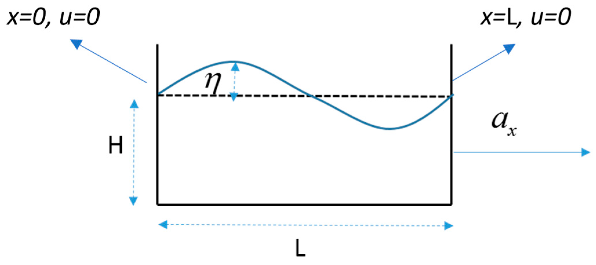
Figure 1. Rectangular tank parameters.
Water 17 02703 g001
Figure 2. Schematic of an SDOF equipped with sloshing water tank.
Water 17 02703 g002
Figure 3. Flowchart used in the present model to couple SDOF dynamic with sloshing tank.
Water 17 02703 g003
Figure 4. Schematic of control volume of node i.
Water 17 02703 g004
Figure 5. Schematic of main and ghost nodes in flow domain in higher-order method.
Water 17 02703 g005
Figure 6. Schematic of nodes and unknowns in Preissmann method.
Water 17 02703 g006
Figure 7. Schematic of nodes and unknowns in staggered method.
Water 17 02703 g007
Figure 8. y = tanh ( x ) diagrams.
Water 17 02703 g008
Figure 9. A half-cosine wave imposed in the model as an initial condition.
Water 17 02703 g009
Figure 10. Different numerical schemes result for wave height at the wall in the perturbation test.
Water 17 02703 g010aWater 17 02703 g010b
Figure 11. Different numerical schemes result for wave height at the wall in the resonance sloshing.
Water 17 02703 g011
Figure 12. Free surface predicted by numerical models.
Water 17 02703 g012
Figure 13. Numerical schemes result for wave height at the wall in the physical diffusion test.
Water 17 02703 g013
Figure 14. System response with and without TLD: (a) numerical response; (b) comparison of numerical and experimental responses.
Water 17 02703 g014
Figure 15. Displacement of the SDOF versus frequency ratios.
Water 17 02703 g015
Figure 16. Displacement of the SDOF versus damping ratios.
Water 17 02703 g016
Table 1. Dynamic properties of the structure and dimension of the water tank.
StructureWater Tank
Mass (kg)Stiffness (KN/m)Daming Coefficient
(KN. s/m)
Length
(m)
Water depth (m)
2824997.54.750.460.04
Disclaimer/Publisher’s Note: The statements, opinions and data contained in all publications are solely those of the individual author(s) and contributor(s) and not of MDPI and/or the editor(s). MDPI and/or the editor(s) disclaim responsibility for any injury to people or property resulting from any ideas, methods, instructions or products referred to in the content.