Article

Identification of Streamline-Based Coherent Vortex Structures in a Backward-Facing Step Flow †

1
State Key Laboratory of Hydrology-Water Resources and Hydraulic Engineering, Nanjing Hydraulic Research Institute, Nanjing 210029, China
2
Powerchina Huadong Engineering Corporation Limited, Hangzhou 310014, China
*
Authors to whom correspondence should be addressed.
This article is a revised and expanded version of a paper entitled “Coherent structure identification in a pressured backward-facing step”, which was presented at the 10th PIANC SMART RIVERS 2022, held in Nanjing, China, 18–21 October 2022.
Water 2025, 17(15), 2304; https://doi.org/10.3390/w17152304 (registering DOI)
Submission received: 26 June 2025 / Revised: 24 July 2025 / Accepted: 1 August 2025 / Published: 3 August 2025

Abstract

Accurately identifying coherent vortex structures (CVSs) in backward-facing step (BFS) flows remains a challenge, particularly in reconciling visual streamlines with mathematical criteria. In this study, high-resolution velocity fields were captured using particle image velocimetry (PIV) in a pressurized BFS setup. Instantaneous streamlines reveal distinct spiral patterns, vortex centers, and saddle points, consistent with physical definitions of vortices and offering intuitive guidance for CVS detection. However, conventional vortex identification methods often fail to reproduce these visual features. To address this, an improved Q-criterion method is proposed, based on the normalization of the velocity gradient tensor. This approach enhances the rotational contribution while suppressing shear effects, leading to improved agreement in vortex position and shape with those observed in streamlines. While the normalization process alters the representation of physical vortex strength, the method bridges qualitative visualization and quantitative analysis. This streamline-consistent identification framework facilitates robust CVS detection in separated flows and supports further investigations in vortex dynamics and turbulence control.

1. Introduction

Vortices play a crucial role in sustaining turbulence and facilitating momentum, energy, and scalar transport in both natural and engineered fluid systems [1]. They are often described as “the sinews and muscles of turbulence”, emphasizing their foundational role in turbulent dynamics [2]. Consequently, understanding and controlling turbulence relies heavily on the accurate identification and characterization of vortex structures.
Despite their importance, a universally accepted definition of a vortex remains elusive. Several classical definitions have been proposed. Lugt (1972) [3] defined a vortex as “the rotating motion of a multitude of material particles around a common center”, emphasizing rotational motion and a shared axis. Robinson (1991) [4] proposed a more detailed definition: “A vortex exists when instantaneous streamlines mapped onto a plane normal to the vortex core exhibit a roughly spiral pattern, when viewed from a reference frame moving with the center of the vortex core”. This definition not only incorporates rotational motion and a common center but also introduces streamlines as a geometric descriptor, consistent with fluid mechanics conventions where closed or spiral streamline patterns denote a vortex. Although these definitions differ in dynamic interpretation, they share a common description of the vortical kinematic characteristics. However, the practical difficulty of determining the instantaneous orientation and motion of the vortex center renders such definitions, while visually intuitive, challenging to apply in quantitative analysis [5].
In response, numerous vortex identification methods have been developed based on different physical and mathematical principles. These include vorticity method, velocity gradient tensor methods (e.g., Q-criterion, λ2-criterion, λci-criterion, Δ-criterion), streamline topology analysis, and pattern recognition techniques. Table 1 summarizes their advantages and limitations.
The IωI method defines vortices based on the magnitude of the vorticity vector with ω being twice the local average angular velocity of fluid elements [6]. Although widely used, this method conflates vorticity with vortex structure, leading to misinterpretation in many cases. For instance, shear flows such as wall turbulence or parallel shear layers exhibit significant vorticity but lack apparent rotational streamlines. Thus, vorticity fails to distinguish vortices from strong shear regions and lacks robustness in vortex structure detection [7,8].
The Δ method identifies vortical regions where the discriminant of the characteristic polynomial of the velocity gradient tensor is positive [9]. This method provides a frame-invariant scalar criterion but lacks physical interpretability regarding vortex strength.
The λci method uses the imaginary part of the complex-conjugate eigenvalues of the velocity gradient tensor to quantify rotational intensity. A positive λci indicates a local swirling motion, but its practical use depends heavily on threshold selection [10].
The λ2 method is based on the second eigenvalue of the pressure Hessian matrix, and a region is defined as vortical if λ2 < 0. This method emphasizes pressure minima associated with vortex cores [11], and is effective in identifying well-developed vortices but may underperform in complex shear layers.
Among these velocity gradient tensor-based methods, the Q-criterion is particularly attractive because it distinguishes rotational and strain-dominated regions using the second invariant of the velocity gradient tensor [12].
In contrast, the streamline topology and pattern recognition methods offer more intuitive insights into large-scale flow organization and are effective in visualizing coherent structures. However, they typically lack frame invariance and often depend on subjective thresholds or empirical flow visualization. Zou et al. (2006) [5] proposed to use the local bending characteristics of streamlines to identify a vortex. By analyzing the streamline shape, the streamline patterns are usually divided into the patterns of the streamline itself and the relative relationship between streamlines. It is pointed out that the former is represented by velocity, curvature and torsion, while the latter requires new discriminant parameters. Finally, the C0 criterion for vortex region identification and the three-parameter criterion {C0, C1, C2} for vortex core region identification are proposed. This method is similar to the vortical concept defined by Robinson (1991) [4] from viewpoint of streamline, but it has not been extended.
Importantly, the application of different identification methods to the same flow field may lead to significantly divergent results, thereby increasing the uncertainty in interpreting the underlying vortex structures.
The backward-facing step (BFS) flow is a fundamental configuration in fluid dynamics and engineering design, commonly encountered in various practical applications. The geometric discontinuity introduced by the step causes flow separation, reattachment, and the development of successive coherent vortex structures (CVSs) in the downstream region. Owing to these characteristics, BFS flow is widely regarded as a classical benchmark for investigating vortex dynamics [13,14,15]. However, the definition and quantitative identification of CVSs in BFS flow remain subjects of considerable debate.
In this study, the BFS configuration is employed to quantitatively extract and analyze the coherent structures generated by step-induced separation. The objective is to evaluate the effectiveness of existing vortex identification methods and to further examine the definition and interpretation of the CVSs.

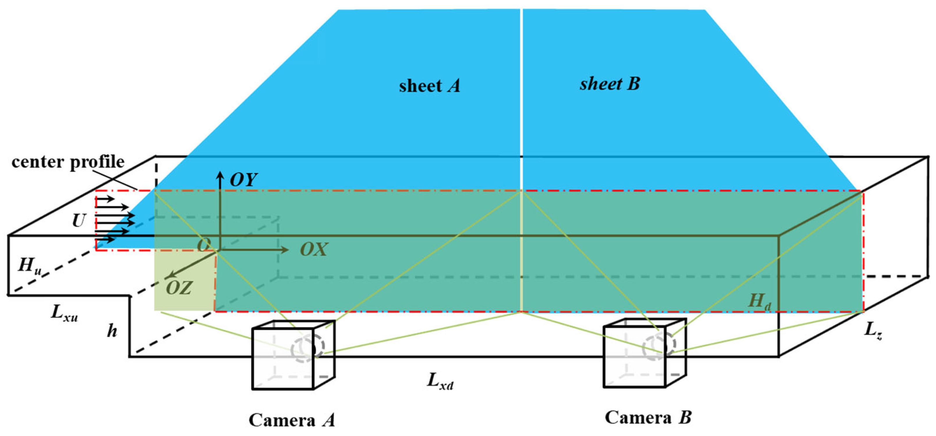
2. Materials and Methods

In this study, a pressurized BFS water tunnel was constructed to investigate the flow characteristics and coherent structures generated by step-induced separation. A planar particle image velocimetry (PIV) system (Nanjing Hawksoft Technology Co.,Ltd., Nanjng, China) was employed to measure the instantaneous velocity fields in the test section (Figure 1).
The BFS model (Laboratory of Fundamental Research on Hydrodynamics, Nanjing Hydraulic Research Institute, Nanjing, China) consists of a rectangular transparent tunnel made of polymethyl methacrylate (PMMA), featuring a vertical step with a height of h = 50 mm at the bottom wall. Honeycomb tubes were installed near the tunnel inlet to ensure fully developed turbulence upstream of the step. The expansion ratio was set to Er = Hd/Hu = 2, where Hu and Hd denote the upstream and downstream water depths, respectively. The tunnel width ratio was defined as Ar = Lz/h = 10 to ensure quasi-two-dimensional flow conditions [16]. The upstream and downstream channel lengths were Lxu = 44 h and Lxd = 50 h, respectively. The configuration parameters are summarized in Table 2.
The PIV system comprised a laser module, an image acquisition unit, and a synchronization control system. The laser module employed a scanning laser system coupled with a light-sheet optical assembly, producing a planar light sheet with a thickness of approximately 1 mm. The laser had an output power of 3 W and a maximum scanning frequency of 40 Hz. The image acquisition module consisted of two same CCD (charge-coupled device) cameras (JAI A/S, Yokohama, Japan) with a resolution of 2560 × 2048 pixels. Neutrally buoyant hollow glass spheres with an average diameter of 15 μm were seeded into the water as tracer particles. Two synchronized laser sheets (labeled A and B) and two corresponding cameras were controlled via a centralized synchronization module. This PIV system enabled global measurements of the instantaneous velocity field within a region of approximately 12 h × 5 h, with a spatial resolution of 7.35 pixels/mm. The interrogation window size used for velocity vector computation was 20 × 15 pixels (equivalent to 2.7 mm × 2.0 mm). The measurement accuracy was within 1% of the maximum flow velocity.
The experiment was conducted under constant head conditions. The Reynolds number was defined as Re = Uh/ν, where U is the bulk velocity measured at a location 1 h upstream of the step, and ν is the kinematic viscosity of water at 20 °C. The experimental flow conditions are listed in Table 3. Re = 4400 was chosen to ensure a well-developed turbulent separation and reattachment flow, while maintaining flow stability suitable for PIV measurements.

3. Results and Discussion

3.1. Streamline-Based Coherent Vortex Structures

Figure 2 presents a comparison of instantaneous flow fields downstream of a BFS, obtained using two different visualization techniques. Figure 2a shows a classical aluminum-powder visualization (adapted from [17]), captured with a short exposure time of 0.5 s. Figure 2b displays the instantaneous streamline field derived from PIV measurements in the present study. Despite the difference in visualization methods and temporal resolution, the two images exhibit remarkably similar flow patterns, particularly in terms of the shape, number, and distribution of streamline-based CVSs. This agreement indicates that streamline topology provides a physically meaningful representation of the coherent structures within the BFS flows.
Both images reveal the essential flow features of BFS-induced separation. The main flow separates at the step edge and reattaches to the bottom wall after a certain distance, forming a prominent recirculation zone. Within this region, a train of CVSs is clearly visible. Approximately three to five CVSs can be identified, with each vortex exhibiting a characteristic spiral pattern. The overall size of these vortices is on the order of the step height, suggesting a strong geometric constraint on their development. Due to their significant role in the dynamics of separated flows, it is essential to accurately define and identify these vortices.
Based on this consistency, we adopt the two-dimensional instantaneous streamlines in this study as the primary tool for identifying and analyzing these CVSs. Although streamlines inherently provide only qualitative representations of the flow field, their topological features—such as spiral trajectories, vortex centers, and saddle points—can be effectively used to approximate the location and size of vortices, thereby supporting further quantitative analysis.
Figure 3 presents a representative streamline field in which each CVS is defined by a closed or nearly closed spiral pattern surrounding a central rotation point (marked in red), referred to as the vortex center Z(x,y). The spatial extent of each CVS is characterized by its horizontal and vertical diameters, Dx and Dy, respectively. The average diameter is calculated as D = 0.5 × (Dx + Dy), while the aspect ratio Dx/Dy provides insight into the geometric deformation of the vortex. In addition, saddle points (blue) are located between adjacent CVSs, delineating zones of topological transition. These parameters form the basis for subsequent quantitative analysis of vortex distribution and evolution.

3.2. Improved Q-Criterion Method

BFS flow is typically characterized by two major shear layers: a free shear layer emanating from the step edge and a wall-bounded shear layer along the lower boundary. Accurate identification of CVSs in such a complex shear environment requires methods that can distinguish between rotational and shear-dominated regions. The Q-criterion, which accounts for both vorticity and strain rate, is, therefore, particularly suitable for analyzing CVSs in BFS flows.
The Q-criterion is derived from the second invariant of the velocity gradient tensor. For an incompressible flow, the characteristic equation of the local velocity gradient tensor ∇U is given as follows:
λ 3 + Q λ R = 0
where λ 1 , λ 2 , λ 3 are the eigenvalues of the tensor. The associated invariants are as follows:
P = λ 1 + λ 2 + λ 3 = d i v U = 0
Q = 1 2 e i j e j i + Ω i j Ω j i = 1 2 Ω i j Ω i j e i j e j i = 1 2 Ω 2 E 2
R = λ 1 λ 2 λ 3 = 1 3 e i j e j k e k i + 3 Ω i j Ω j k Ω k i
where e i j , Ω i j represent the strain rate tensor and vorticity tensor, respectively.
In two-dimensional flows, the velocity gradient matrix is expressed as follows:
U = u x u y v x v y
The Q-criterion is then simplified to the following:
Q = 1 2 Ω 2 s 2
where
Ω = 1 2 U U T
Ω is the rotation rate tensor, representing the antisymmetric part of the velocity gradient tensor and corresponding to pure rigid-body rotation in the flow;
S = 1 2 U + U T
S is the strain rate tensor, representing the symmetric part of the velocity gradient tensor and corresponding to pure shear deformation in the flow.
In practice, regions where Q > 0 are typically considered to contain vortex cores. However, due to the continuous nature of the transition between vortical and background flow regions, no universally defined threshold exists. A threshold value is needed to identify the most important part of CVSs [11,18], and the selected threshold value should consider the objective flow characteristics [19].
Figure 4 compares the CVSs identified using instantaneous streamlines and those detected by the Q-criterion. Significant differences are observed between the two methods. In particular, the Q-criterion fails to clearly distinguish between vortices originating from the free shear layer and those induced by the near-wall boundary. This discrepancy arises from the characteristic shear-dominated nature of the BFS flow. Unlike typical open-channel near-wall turbulence, the BFS configuration exhibits exceptionally high shear intensity, especially near the wall and separation point. In these regions, the local strain rate often exceeds the rotational strength, which suppresses the Q value and hinders the detection of vortex cores. Moreover, the identification results are highly sensitive to the choice of threshold, further complicating the extraction of CVSs consistent with those observed in streamline patterns. Therefore, to achieve a more accurate representation of CVSs as captured by streamline topology, it is necessary to improve the traditional Q-criterion approach.
The vortex structures characterized by streamlines are primarily governed by local rotational strength, whereas the Q-criterion reflects the balance between rotational and shear components of the flow. In the context of BFS flow, where shear often dominates, this can lead to an underrepresentation of coherent vortical patterns when using the Q-criterion.
To address this issue, we propose a normalization strategy that enhances the rotational component and suppresses the shear contribution in the velocity tensor. We believe that velocity normalization enhances the detection of rotational features (swirling behavior) without altering the vertical positioning of vortices in the flow field. This choice allows for a more physically meaningful identification of CVSs, especially in the presence of strong shear. Specifically, the velocity component matrices are normalized using Equations (9) and (10), prior to computing the Q-value based on the standard definition.
As shown in Figure 5, the improved Q-criterion method begins with the normalization of velocity components to suppress excessive shear dominance and enhance rotational feature extraction. This modification ensures better alignment between Q-based identification results and the streamline-defined coherent structures.
u ~ = u u 2 + v 2
v ~ = v u 2 + v 2
Figure 6 illustrates the identification and comparison of CVSs using the improved method. Compared with Figure 6a, Figure 6b presents the vortex regions identified by the improved Q-criterion method (red circles), which not only captures the prominent CVSs evident in the streamline patterns but also successfully detects smaller-scale vortex structures that are less visually distinguishable. Figure 6c displays the post-processed segmentation results, where CVSs are represented as distinct image patches for enhanced visualization and analysis.
These results confirm that the improved Q-criterion provides a robust and reliable tool for the CVSs identification in BFS flows. Beyond improving detection accuracy, it facilitates subsequent quantitative analyses of CVS’s distribution, shape, and scale, thereby supporting more in-depth investigations of particularly vortical dynamics and evolution in the separated flows.
Table 4 provides a quantitative comparison of CVSs identified by streamlines, the standard Q method, and the improved Q method. The streamlines revealed six dominant CVSs with clear rotational centers and well-aligned trajectories in Figure 4a. In contrast, the standard Q method produced a significantly larger number of small-scale structures (35 in total), many of which did not correspond to coherent features seen in the streamline visualization, resulting in a mismatch in both center location and shape. The improved Q method, however, identified 13 CVSs, which not only included and aligned closely with the streamline-defined cores, but also exhibited similar average vortex size (D/h = 0.3). This consistency supports the improved method’s effectiveness in capturing physically meaningful CVSs in the BFS flow.

3.3. Discussion

Among various vortex identification techniques, the Q method is widely used due to its solid theoretical foundation. It is based on the second invariant of the velocity gradient tensor, which quantifies the difference between the local rotation rate and strain rate, thereby reflecting the balance between rotational and shear motions in the flow. When Q > 0, rotational motion dominates over strain, and the region is typically identified as a vortex core.
In open-channel turbulent flows, Chen, Q.G. (2014) [19] compared several methods—Δ, λci, λ2 and Q—and concluded that all can effectively identify vortical structures, with consistent results when appropriate thresholds are applied, in line with the findings of Chakraborty et al. (2005) [18] in 3D flows. However, the backward-facing step (BFS) flow presents a more complex configuration. It features both a strong free shear layer and wall-induced effects, with vortices evolving through separation, reattachment, and interaction with boundaries. In such cases, the standard Q method may struggle to distinguish true rotational CVSs from regions dominated by strong shear, particularly near the reattachment zone and bottom wall.
To address this limitation, this study proposes an improved Q method that applies normalization to the velocity gradient tensor. This enhances the prominence of rotational components while mitigating the masking effect of shear, allowing more accurate and consistent identification of CVSs. As demonstrated in Figure 6, the vortex cores identified by the improved Q method show strong spatial and morphological agreement with those revealed by instantaneous streamlines, including small-scale structures.
A key advantage of the improved Q method lies in its ability to bridge streamline-based visualization and quantitative vortex identification. In complex flows like BFS, where coherent structures are clearly visible in streamlines but hard to isolate by standard mathematical tools, the improved method enables this visual topology to be translated into precise mathematical expressions, laying the foundation for further quantification of vortex size, location, and shape. Although both the standard Q method and the improved Q method are capable of identifying vortical structures, the results differ significantly, as shown in Figure 4 and Figure 5. As a plausible inference, such as for the open-channel turbulent flows, the improved Q method may also yield vortex structures that align more closely with the streamline patterns. This suggests that the method could be applicable beyond the BFS configuration.
Nonetheless, this approach also has notable limitations. While the normalization process improves pattern recognition, it also alters the magnitude of rotational strength, making the resulting Q values less representative of the true physical intensity of the vortices. As such, while positional and morphological agreement is enhanced, the vortex strength itself cannot be reliably inferred from the normalized Q values. Future work may consider hybrid approaches that retain magnitude scaling for core intensity estimation while applying normalization only to directional gradients for structure identification. Additionally, using inverse normalization coefficients could help recover relative vortical strength information. Furthermore, the method still depends on empirical thresholding, and its application is presently limited to two-dimensional fields, whereas many actual turbulent structures are inherently three-dimensional.
In summary, the improved Q method offers an effective mathematical tool for visual-consistent CVS’s identification in BFS flows. It enhances the interpretability of vortex features and provides a framework for connecting flow visualization with mathematical analysis. However, caution must be exercised when interpreting vortex intensity, and complementary techniques or full 3D analysis may be required for more complete flow characterization.

4. Conclusions

This study investigates the coherent vortex structures (CVSs) in backward-facing step (BFS) flow through a combination of flow visualization, streamline analysis, and quantitative vortex identification methods. Key conclusions are as follows:
(1)
Instantaneous streamlines effectively reveal CVSs such as spiral patterns, vortex centers, and saddle points. These topological features correspond well to the common vortical definition and streamlines can serve as a qualitative basis for the CVS’s identification.
(2)
Characteristic parameters such as vortex center, diameter, and saddle points were defined to describe the morphology and distribution of CVSs. This offers a structured framework for further quantitative analysis for the CVSs.
(3)
The standard Q method, though theoretically robust, showed limitations in identifying vortices in BFS flows due to strong shear effects. An improved Q method was developed by normalizing the velocity gradient tensor, which enhanced the relative rotational intensity and significantly improved spatial agreement with the structures shown in streamlines.
(4)
The improved Q method establishes a link between streamline visualization and mathematical identification, enabling mathematical detection of vortical position and shape. However, the normalization process distorts physical strength, limiting its use in vortex intensity quantification.
Overall, the proposed streamline-consistent identification strategy, supported by an enhanced Q-criterion, offers a robust and physically meaningful approach for detecting and analyzing coherent structures in separated flows such as BFS. This framework lays a foundation for future work on vortex dynamics, turbulence control, and model validation.

Author Contributions

Conceptualization, F.W. and S.W.; Data curation, C.S. and Z.Z.; Formal analysis, X.Y. and P.C.; Methodology, X.Y., P.C. and C.S.; Project administration, X.W.; Resources, X.W.; Supervision, S.W.; Writing—original draft, F.W.; Writing—review and editing, F.W. and Z.Z. All authors have read and agreed to the published version of the manuscript.

Funding

This research is funded by the National Natural Science Foundation of China (Grant No. 51909169). The authors gratefully acknowledge the financial supports.

Data Availability Statement

The data presented in this study are available upon request from the corresponding authors.

Acknowledgments

The authors would like to express their sincere gratitude to the experimental support at Nanjing Hydraulic Research Institute. Special thanks are extended to Nanjing Haokong Technology Co., Ltd. (Nanjing, China) for their assistance with the PIV measurements. This article is a revised and expanded version of a paper [20], which was presented at the 10th PIANC SMART RIVERS 2022, held in Nanjing, China, 18–21 October 2022.

Conflicts of Interest

Authors Xuesong Yu and Peng Chen were employed by the company Powerchina Huadong Engineering Corporation Limited. The remaining authors declare that the research was conducted in the absence of any commercial or financial relationships that could be construed as a potential conflict of interest.

Abbreviations

The following abbreviations are used in this manuscript:
BFSBackward-Facing Step
CVSCoherent Vortex Structure
PIVParticle Image Velocimetry
PMMAPolymethyl-Methacrylate
CCDCharge-Coupled Device
ReReynolds Number
Q-criterionSecond Invariant of Velocity Gradient Tensor
3DThree-dimensional

References

  1. Chen, Q.; Zhong, Q.; Qi, M.; Wang, X. Comparison of vortex identification criteria for planar velocity fields in wall turbulence. Phys. Fluids 2015, 27, 085101. [Google Scholar] [CrossRef]
  2. Küchemann, D. Report on the IUTAM symposium on concentrated vortex motions in fluids. J. Fluid Mech. 1965, 21, 1–20. [Google Scholar] [CrossRef]
  3. Lugt, H.J. Vortex Flow in Nature and Technology; 1984 translation; Wiley-Interscience: New York, NY, USA, 1983; p. 305. [Google Scholar]
  4. Robinson, S.K. Coherent motions in the turbulent boundary layer. Annu. Rev. Fluid Mech. 1991, 23, 601–639. [Google Scholar] [CrossRef]
  5. Zou, W.N.; Zhao, Y.; Dong, H. Vortex Detection Based on Streamline Analysis. 2006. Available online: https://wenku.baidu.com/view/9f99c31ea300a6c30c229ff1?pcf=2&bfetype=new&_wkts_=1753342839176&needWelcomeRecommand=1 (accessed on 25 July 2025). (In Chinese).
  6. Bisset, D.K.; Antonia, R.A.; Browne, L.W.B. Spatial organization of large structures in the turbulent far wake of a cylinder. J. Fluid Mech. 1990, 218, 439–461. [Google Scholar] [CrossRef]
  7. Li, Z.; Zhang, X.W.; He, F. Evaluation of vortex criteria by virtue of the quadruple decomposition of velocity gradient tensor. Acta Phys. Sinika 2014, 63, 701–704. [Google Scholar]
  8. Tian, S.; Gao, Y.; Dong, X.; Liu, C. Definitions of vortex vector and vortex. J. Fluid Mech. 2018, 849, 312–339. [Google Scholar] [CrossRef]
  9. Chong, M.S.; Perry, A.E.; Cantwell, B.J. A general classification of three-dimensional flow fields. Phys. Fluids A Fluid Dyn. 1990, 2, 765–777. [Google Scholar] [CrossRef]
  10. Zhou, J.; Adrian, R.J.; Balachandar, S.; Kendall, T.M. Mechanisms for generating coherent packets of hairpin vortices in channel flow. Phys. Fluids 1999, 387, 353–396. [Google Scholar] [CrossRef]
  11. Jeong, J.; Hussain, F. On the identification of a vortex. J. Fluid Mech. 1995, 285, 69–94. [Google Scholar] [CrossRef]
  12. Hunt, J.C.; Wray, A.A.; Moin, P. Eddies, streams, and convergence zones in turbulent flows. In Studying Turbulence Using Numerical Simulation Databases, 2. Proceedings of the 1988 Summer Program, 1 December 1988; Ames Research Center: Mountain View, CA, USA, 1988. [Google Scholar]
  13. Hu, R.Y.; Wang, L.; Fu, S. Investigation of the coherent structures in flow behind a backward-facing step. Int. J. Numer. Methods Heat Fluid Flow 2016, 26, 1050–1068. [Google Scholar] [CrossRef]
  14. Kostas, J.; Soria, J.; Chong, M. Particle image velocimetry measurements of a backward-facing step flow. Exp. Fluids 2002, 33, 838–853. [Google Scholar] [CrossRef]
  15. Wang, F.; Gao, A.; Wu, S.; Zhu, S.; Dai, J.; Liao, Q. Experimental investigation of coherent vortex structures in a backward-facing step flow. Water 2019, 11, 2629. [Google Scholar] [CrossRef]
  16. Bradshaw, P.; Wong, F.Y.F. The reattachment and relaxation of a turbulent shear layer. J. Fluid Mech. 1972, 52, 113–135. [Google Scholar] [CrossRef]
  17. Tani, I.; Iuchi, M.; Komoda, H. Experimental investigation of flow separation associated with a step or a groove. Aeronaut. Res. Inst. Univ. Tokyo 1961, 27, 119–137. [Google Scholar]
  18. Chakraborty, P.; Balachandar, S.; Adrian, R.J. On the relationships between local vortex identification schemes. J. Fluid Mech. 2005, 535, 189–214. [Google Scholar] [CrossRef]
  19. Chen, Q.G. High-Frequency Measurement of Vortices in Open Channel Flow with Particle Image Velocimetry. Ph.D. Thesis, Tsinghua University, Beijing, China, 2014. [Google Scholar]
  20. Wang, F.F.; Sun, Z.X.; Sun, C.G.; Fan, G.F.; Zhang, W.L.; Xu, J.Y. Coherent structure identification in a pressured backward-facing step. In Proceedings of the PIANC Smart Rivers 2022, Nanjing, China, 18–21 October 2022. [Google Scholar]
Figure 1. Schematic of the test section with a PIV system: blue: laser sheets; yellow: Camera fields of view.
Water 17 02304 g001
Figure 2. Coherent vortex structures in a backward-facing step: (a) Aluminum-powder visualization (adapted from Tani et al., 1961 [17]; exposure time: 0.5 s); (b) PIV-derived instantaneous streamline in present study.
Water 17 02304 g002
Figure 3. Schematic diagram illustrating characteristic parameters of coherent vortex structures (CVSs): Dx and Dy represent the diameters in X and Y directions, respectively; Z(x,y) denotes the vortex center (red point); blue points represent saddle points between adjacent CVSs.
Water 17 02304 g003
Figure 4. Comparison of coherent vortex structures (CVSs) with different methods: (a) Instantaneous streamlines; (b) Standard Q-criterion method.
Water 17 02304 g004
Figure 5. Workflow of the improved Q-criterion method.
Water 17 02304 g005
Figure 6. Identification and comparison of CVSs with the improved method: (a) Instantaneous streamlines; (b) Improved Q-criterion method with red circles indicating concentrated vortex cores; (c) Post-processed segmentation results. The same instantaneous streamline/velocity field was used with Figure 4 and the vortical color is categorical rather than vortical strength.
Water 17 02304 g006
Table 1. Comparison of vortex identification methods.
MethodsAdvantagesLimitations
Vorticity (IωI)Simple implementation; effective in detecting strong rotational regionsCannot distinguish between rotation and shear; may misidentify shear layers as vortices
Velocity gradient tensor (e.g., Q-criterion, λ2-criterion, λci-criterion, Δ-criterion)Physically grounded; Galilean invariant; suitable for local vortex detectionSensitive to noise; requires eigenvalue or Hessian computations; computationally expensive
Streamline topologyIntuitive and visually interpretable; applicable to unsteady flowsNot Galilean invariant; depends on reference frame; requires full-field data
Pattern recognition/matching Flexible and extendable; can integrate machine learning for automationSubjective parameter/template selection; limited generalizability
Table 2. Configuration parameters of the BFS model.
ParametersValuesUnits
h50mm
Lxu2220mm
Lxd2500mm
Hu50mm
Hd100mm
Lz500mm
i0
Er2:1-
Ar10:1-
Table 3. Flow conditions in the experiment.
h (cm)U (m/s)ErArReXr/h
50.0882:11044006.1
Table 4. Quantitative comparison of coherent vortex structures (CVSs) identified by different methods.
MethodsNumberZ(x,y)D/hOverall Evaluation
Streamlines6/0.3/
Standard Q35Not matched0.2Inconsistent
Improved Q13Matched0.3Consistent
Disclaimer/Publisher’s Note: The statements, opinions and data contained in all publications are solely those of the individual author(s) and contributor(s) and not of MDPI and/or the editor(s). MDPI and/or the editor(s) disclaim responsibility for any injury to people or property resulting from any ideas, methods, instructions or products referred to in the content.

