1. Introduction
With the deepening of China’s energy structure reform, pumped storage power stations play an important role in peak shaving, frequency modulation, phase modulation, emergency standby, and other aspects of the power system because of their fast opening and closing speed and flexible regulation [
1,
2]. Different from the traditional hydraulic turbine, the pump turbine adopts the reversible structural design, taking the pump condition as the optimum design condition [
3]. The main defect of this design is the existence of the SFR. When the PSU is started at a low head, it is easy to enter the SFR, causing the unit to oscillate, leading to failed unit startup, which is not conducive to the simultaneous grid connection [
4,
5]. In order to solve the problem of the low-head startup stability of the PSU, domestic and foreign scholars have mainly studied three aspects: flow mechanism, influencing factors, and measures.
(1) Study the flow mechanism in the pump turbine and clarify the flow characteristics and sources of S characteristics.
From initially recognizing the adverse impact of pump turbine S characteristics on unit operation, researchers have tried to explain the flow characteristics and sources of S characteristics from the view of the flow mechanism. Xiao et al. [
6] found that pressure pulsation in the passage is caused by rotor–stator interference between the runner and the guide vane, the vortex in the blade passage of the runner, and the vortex rope in the draft tube. Hasmatuchi et al. [
7] found that the S characteristics are the result of the separation of rotating flow in several continuous impeller channels. Widmer et al. [
8] found that the static vortex formation and rotating stall initially have the same physical reasons, which depend on the average convective acceleration in the guide vane channel. Sun et al. [
9] found that the process of S characteristics is related to the centrifugal force and the large incident angle under low-flow conditions. A large vortex is formed between the guide vane and the vane inlet, and the strong flow recirculation in the blade-free space is the main factor leading to the S-shaped characteristic. Mao et al. [
10] found that the dominant vortex near the inlet of the runaway channel leads to speed no-load instability. Staubli et al. [
11] found that the vortex formation in the inlet section of the channel domain will periodically and seriously block the through flow in the channel, causing flow rate and speed fluctuations. Sun et al. [
12] found that since the curvature of the streamline in the pump turbine is greater than that of its Francis turbine, it is expected to generate greater centrifugal force, forming vortices in the bladed space. Based on the reviewed research, it is evident that the existence of the vortex structure in the runner and guide vane passage and the strong pressure fluctuation between the runner and guide vane are the fundamental reasons for the formation of the SFR of the pump turbine. A large number of vortices formed at the inlet of the runner blade blocks the whole runner channel so that the water flow cannot flow smoothly through the runner, and the overcurrent capacity of the unit decreases. Ultimately, the unit enters the unstable region owing to progressive flow reduction, constituting the primary cause of the SFR of the pump turbine.
(2) Change the hydraulic design parameters and eliminate the SFR.
The performance of the pump turbine changes with geometric parameters such as impeller diameter, blade wrapping angle, impeller inlet width, and blade inlet angle [
13]. Olimstad et al. [
14] found that the leading edge of the blade with a longer curvature radius makes the formation of a vortex move towards a higher rotation speed. Zhu et al. [
15] found that the flow passage with a negative blade inclination has better instability, that is, weak S-shaped characteristics. Yin et al. [
16] proposed a method to improve the S characteristics of medium-speed water pump turbines. This method determines the flow channel as the main cause of instability and optimizes the outlet diameter, inlet diameter, and inlet blade height of the flow channel. Ref. [
14] found that in turbine mode, the radius of curvature on the pressure side of the leading edge of the turbine should be increased, the inlet radius should be reduced, the angle of the inlet blade should be increased, or the length of the blade should be increased to make the pump turbine more stable.
(3) Measures to improve S characteristics.
The development of pumped storage power stations in China is very rapid. Many pumped storage power stations adopt the misaligned guide vanes method to eliminate S characteristics and improve stability. However, this also results in significant pressure pulsation in the runner. Although the misaligned guide vanes method improves the S characteristics of the pump turbine, the unbalanced radial force and pressure fluctuation on the flow channel lead to unstable operation under no-load conditions [
9]. In order to improve the performance of the misaligned guide vanes method of Yu et al. [
17], according to the characteristics of the pump turbine and the main inlet valve, a new closure law combining gate closure and the main inlet valve is proposed. The proposed closure law can reduce the influence of S characteristics, the maximum pressure in the spiral case, the maximum speed of the flow passage, and the minimum pressure in the draft tube in the transient process.
In summary, prior studies primarily addressed S-characteristic elimination through two approaches: improving the design parameters and changing the flow field. However, although these methods can weaken the SFR to a certain extent, they also have other adverse effects. This paper started from the direction of how to avoid the SFR, introduced the concept of the SFR boundary, analyzed the specific conditions under which PSUs avoid the SFR during startup from a geometric perspective, and gave guiding opinions on the startup process of PSUs. In this study, the term “geometric perspective” refers specifically to a spatial relationship analysis framework that quantifies the relative position and critical distance threshold of the no-load operating trajectory and the SFR boundary on the (n11, Q11) characteristic plane, which differs from traditional projective geometry or hydraulic component design.
In contrast to prior studies, predominantly focused on mitigating S-shaped characteristics through hydraulic design modifications or flow field alterations—approaches often entailing performance compromises—this study proposes a fundamentally distinct paradigm centered on operational strategy optimization. The core methodological innovations include
(1) A novel geometric perspective is established to quantify the positional relationship between the no-load operating point trajectory and the precisely defined SFR boundary. This framework enables the calculation of the critical distance threshold for instability avoidance.
(2) The Hopf bifurcation principle is employed to analyze the critical transition state where the system enters the SFR, providing theoretical grounding for stability boundaries.
(3) Based on the above theoretical foundations, two necessary and sufficient conditions for successful SFR avoidance are derived: (i) stable region operation and (ii) speed overshoot below a geometrically determined critical threshold.
This work provides concrete theoretical guidance and quantitative criteria for optimizing the startup process of PSU facing SFR challenges, particularly under low-head conditions.
2. Model of Pumped Storage Unit Governing System
2.1. Fundamental Equations
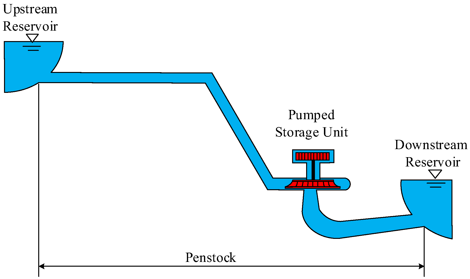
The pumped storage unit governing system integrates hydraulic, mechanical, and electrical operations [
18]. Its subsystems include pressure piping, a pump turbine, a generator, and a governor, as shown in
Figure 1. The fundamental equations of each subsystem are as follows.
(1) Penstock model
The penstock model focuses on the dynamic process of pressure in the overflow pipe and the acting head of the pump turbine, usually described by the water hammer mode. The water hammer model includes the rigid water hammer model and elastic water hammer model. Due to the complexity of solving the elastic water hammer model, the rigid water hammer model is often used for research in engineering, and its mathematical expression is [
19]
where
is the relative value of head deviation;
is the relative value of flow deviation; and
is the flow inertia time constant of penstock.
(2) Nonlinear pump turbine model
The no-load startup of the PSU belongs to the small disturbance condition. At this time, the pump turbine model is expressed by the moment equation and discharge equation under the steady-state condition as follows [
20]:
where
is the relative value of kinetic moment;
is the relative value of rotor speed;
is the relative value of guide vane; and
,
,
,
,
, and
are the transfer coefficients of the pump turbine.
Considering the strong nonlinear characteristics of the pump turbine, the transfer coefficients of the pump turbine should be time-varying—the transfer coefficients of the pump turbine change with operation points. The time-varying transfer coefficients of the pump turbine are derived via the following method [
21]:
where
,
,
,
,
, and
are the transfer coefficients of the pump turbine at the initial time.
Then the nonlinear pump turbine model can be obtained:
Equation (4) demonstrates that the moment and discharge equations exhibit nonlinearity, and the transfer coefficients of the pump turbine can change with head and speed. It should be noted that this paper assumes that the S-shaped characteristics of the prototype unit are similar to those of the model unit. In reality, there are differences between the S-shaped characteristics of the two units. These differences can be corrected using the S-curve characteristics of the model unit or by conducting tests on the prototype unit to obtain more accurate S-curve characteristics for the prototype unit. However, studying the issues addressed in this paper based on the given S-shaped characteristics does not affect its conclusions.
(3) Generator model
Most of the generators used in PSUs are synchronous generators. If only considering the influence of the mechanical regulation of synchronous generators, using the rotor motion equation, the generator model can be expressed by [
22]:
where
is the unit inertia time constant; and
is the relative value of the load.
(4) Governor model
The pumped storage unit governing system adopts frequency regulation mode during no-load operation. At this time, the governor usually adopts a PID control strategy, and the governor model can be expressed by [
23]
where
is servomotor response time constant;
is proportional gain;
is integral gain; and
is differential gain.
2.2. Nonlinear Mathematical Model
The nonlinear state space equation of the pumped storage unit governing system under frequency regulation mode is obtained by coupling Equations (1)–(6):
where
is the intermediate variable.
2.3. Model Assumptions and Simplifications
The pumped storage governing system model established by this research institute is based on the following assumptions and simplifications:
(1) Assuming that the water flow is an incompressible fluid and ignoring the influence of water compressibility on the propagation of pressure waves. This assumption simplifies the conservation of mass equations, making pressure changes only related to the time-varying characteristics of flow rate.
(2) Assuming the pressure pipeline is an absolutely rigid structure, ignoring the elastic deformation of the pipe wall and the frictional loss of water flow, and only retaining the inertial effect of water flow. This type of simplification is suitable for short pipelines or low-flow-rate scenarios but may introduce errors for long pipelines or high-flow-rate systems.
(3) Assuming that the flow is uniformly distributed along the axial direction of the pipeline, ignoring the radial and tangential velocity changes, and only retaining the average axial velocity.
(4) Under small disturbance conditions (such as no-load start-up), it is assumed that the inertia of water flow dominates the dynamic process, while the influence of high-frequency pressure fluctuations can be ignored. At this point, the pump turbine model approximates the dynamic behavior using the transfer coefficient under steady-state conditions.
(5) Assuming the controller operates as an ideal linear system and ignoring the effects of nonlinear hysteresis.
(6) Assuming that the electromagnetic damping effect of the generator is not significant and the rotor dynamics are dominated by mechanical inertia.
(7) Assuming that the S-shaped characteristics of the model and the comprehensive characteristic curve of the prototype have complete similarity.
These assumptions and simplifications may affect the accuracy of the model to some extent, but they do not affect the research on the mechanism of avoiding the SFR that this article intends to conduct. In engineering applications, assumptions and simplifications should be reduced, especially in hydraulic systems with long water diversion pipelines where pipeline deformation and water flow friction losses should be considered.
3. Description of the S-Shaped Region
The SFR of pump turbines will cause the PSU to switch back and forth between the three working conditions of a turbine, turbine braking, and reverse pump during low-head startup. At this time, the frequency of the unit fluctuates violently and cannot be connected to the grid successfully.
To study the mechanism of the PSU avoiding the SFR of the pump turbine during the startup process, describing the SFR of the pump turbine accurately is very important. In the past, it was generally believed that the SFR of the pump turbine was the anti-SFR in the speed flow relationship curve of the pump turbine. This understanding of the SFR is not accurate, and it is also unfavorable to the study of related problems. Considering that the corresponding three different unit flows under the same unit speed are in the SFR of the pump turbine, the accurate range of the SFR can be drawn based on this feature.
3.1. Pump Turbine Extreme Speed Operation Points
Figure 2 shows the positions of the local maximum and minimum values of the turbine speed under the same guide vane opening conditions.
For compatibility with IEC 60193 standard, conversion factors between the traditional coefficients (
,
) and IEC coefficients (
,
) are provided:
where
g is the gravitational acceleration.
Mathematically, the local maximum and minimum unit speeds are derived from the system of Equations (10)–(12). Specifically,
The local minimum unit speed operating point occurs when Equations (10) and (11) are simultaneously satisfied. The local maximum unit speed operating point arises when Equations (10) and (12) are concurrently satisfied.
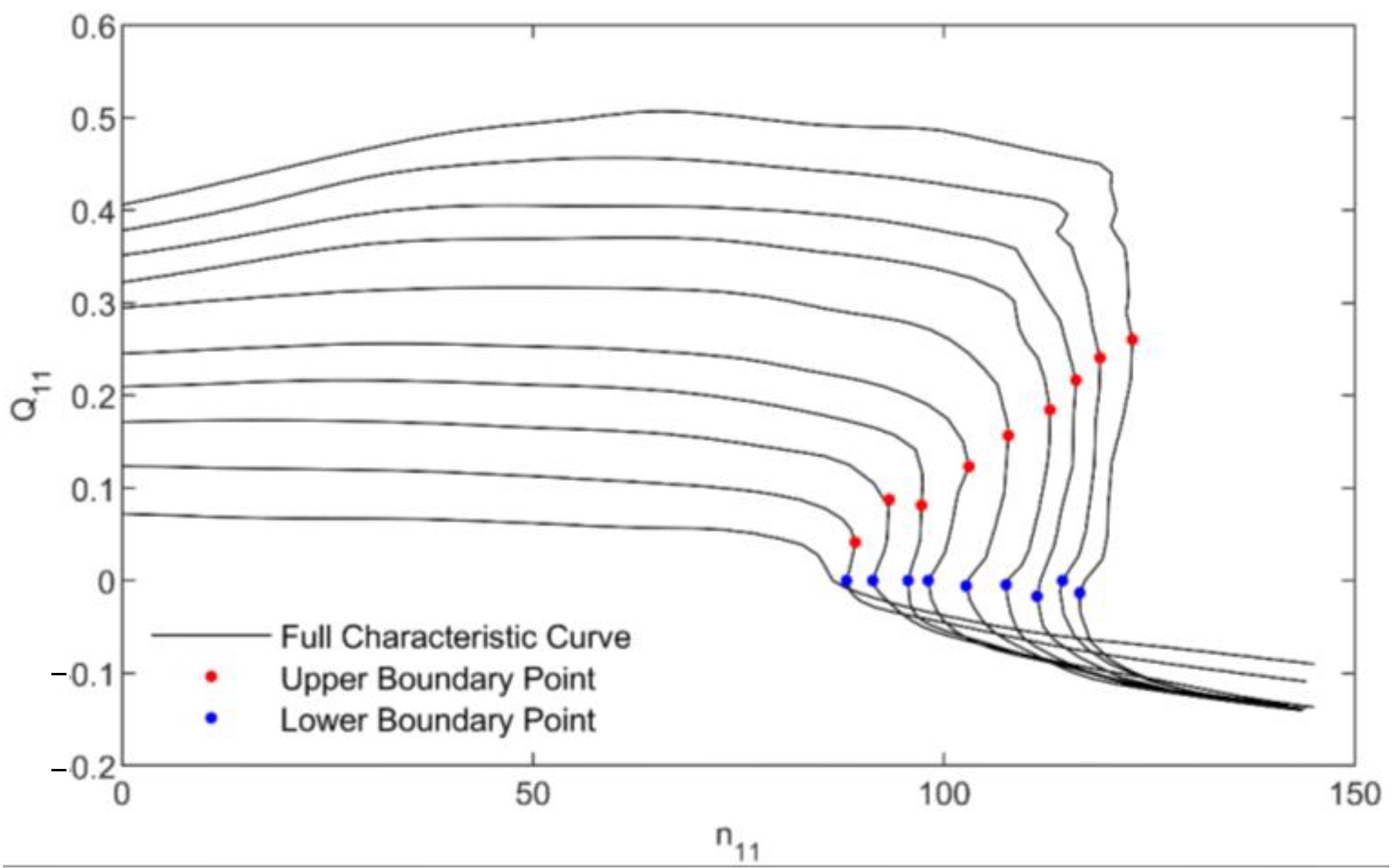
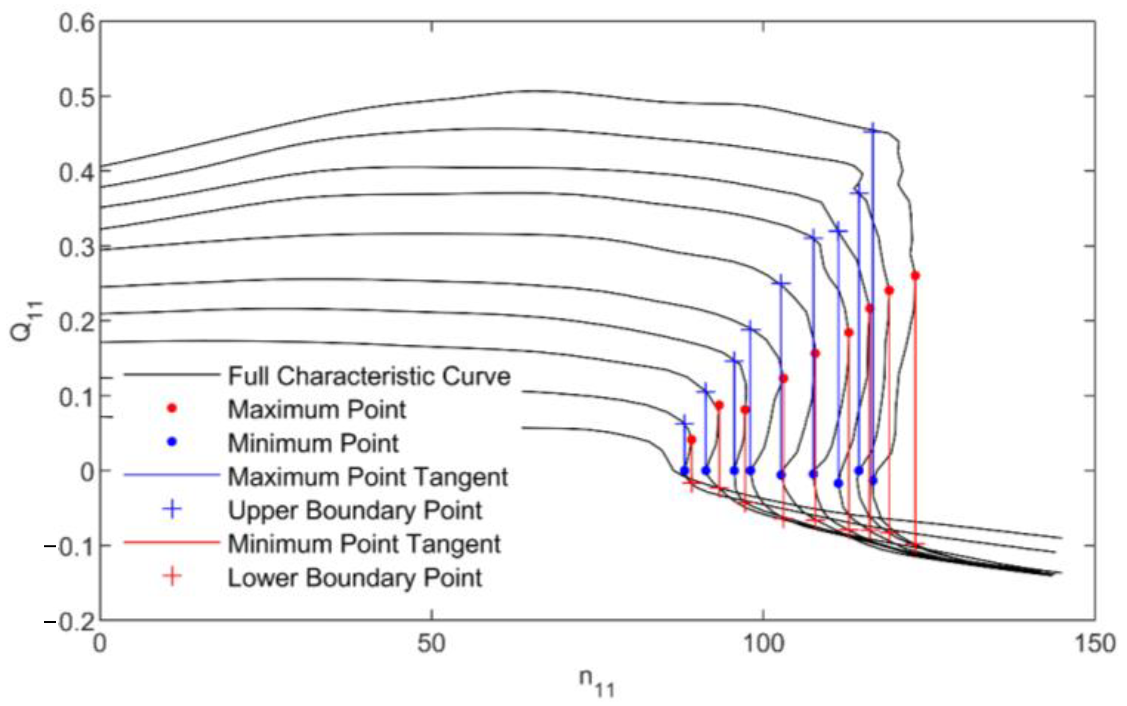
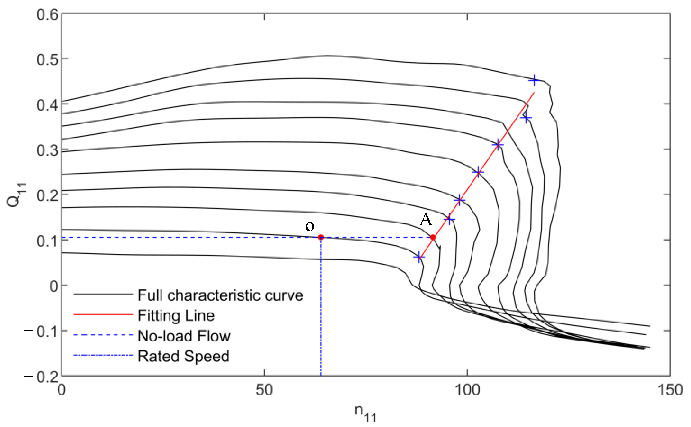
3.2. Upper and Lower Boundary Points of Pump Turbine S-Shaped Region
Figure 3 shows the upper and lower boundary points of the SFR. The full characteristic curve shows that with the same guide vane opening when the pump turbine speed is equal to the local maximum value or local minimum value of the speed, the same unit speed corresponds to the two flows. This should be the critical condition for the PSU to enter the SFR during operation. The local maximum point of the unit speed of the pump turbine corresponds to the lower boundary point of the SFR. The local minimum value point of the unit speed of the pump turbine corresponds to the upper boundary point of the SFR of the pump turbine. Therefore, in the full characteristic curve of the pump turbine, the SFR has upper and lower boundary points. These points are found where tangents drawn at the local maximum and minimum operating points intersect the corresponding equal guide vane opening line for each guide vane opening.
Under different guide vane openings, the upper boundary point of the SFR can be obtained by interpolating the local minimum speed at the operation points less than the local maximum speed, while the lower boundary point of the SFR of the pump turbine can be obtained by interpolating the local maximum speed at the operation points greater than the local minimum speed.
It should be noted that experimentally observed hysteresis effects may influence the precise determination of boundary points. In some cases, the dynamic transition paths between operating points exhibit loop-like trajectories in the characteristic curve, leading to deviations from the static boundary definitions proposed here. Future work will incorporate transient hysteresis modeling to refine boundary accuracy.
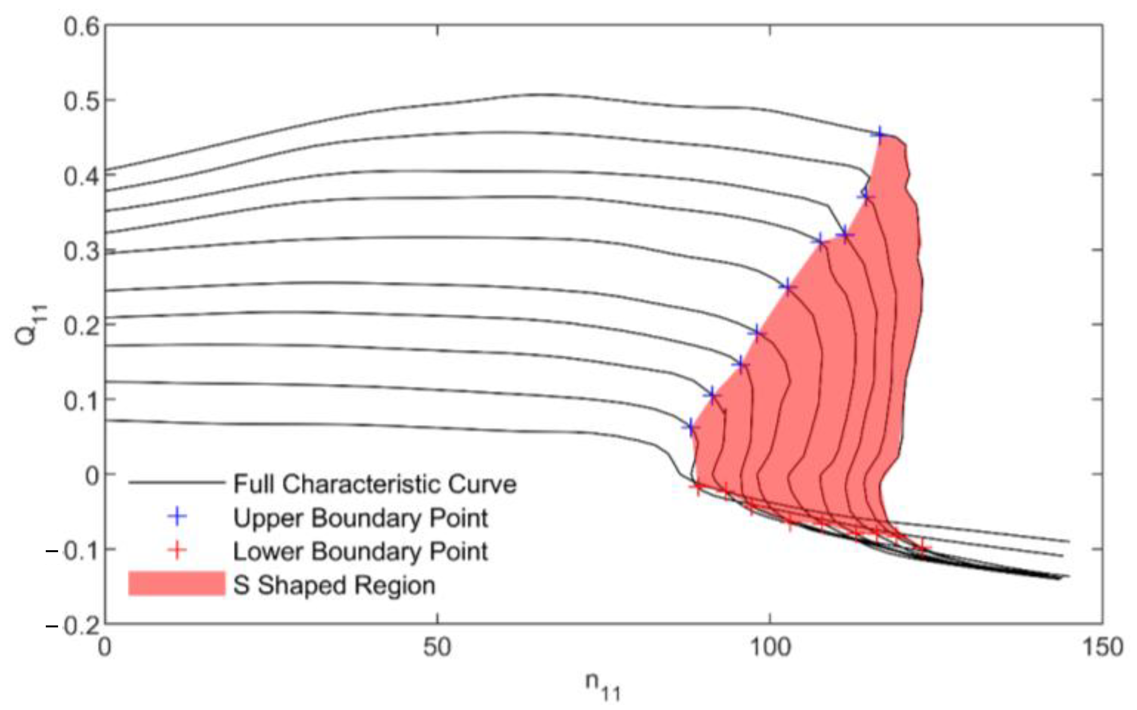
3.3. Pump Turbine S-Shaped Region
Figure 4 shows the SFR of the pump turbine. By observing the full characteristic curve of the pump turbine, it can be seen that under the same guide vane opening, the same unit speeds corresponding to three different unit flows all occur between the upper boundary point and the lower boundary point of the pump turbine SFR. Therefore, the upper and lower boundary of the pump turbine SFR and the part surrounded by the boundary is the pump turbine SFR.
4. Study on Startup Law of Pumped Storage Units
After the PSU receives the startup command of the hydraulic turbine under static conditions, the governor will open the guide vane according to a certain law and control the unit to start in the direction of the hydraulic turbine [
24]. Most of the hydraulic turbine startup methods of the PSU in China follow the traditional startup method of hydropower units, which generally adopts the “open-loop + closed-loop” mode; that is, at the initial stage of startup, the speed feedback signal is not introduced, the control system is open-loop, the governor controls the guide vane to open according to a certain law, when PSU speed rises to near the rated speed, and then the speed feedback signal is introduced. The governor adjusts the speed of the unit to the rated speed according to the closed-loop control law (generally PID control), and the grid connection is pending [
25].
The basic data of pumped storage power station used in this chapter are as follows: the rated head
, rated flow
, rated speed
, and unit inertia time constant
. Other parameters are the water flow inertia time constant
, no-load flow
, no-load opening
, servomotor time constant
, and differential gain
(adopt the Stein formula [
26]). The ideal transfer coefficient is used for the initial transfer coefficient of the pump turbine, so
,
,
,
,
,
.
4.1. Mechanism to Avoid S-Shaped Region
In order to ensure the successful startup of the PSU, without changing the flow pattern, during the startup of the PSU, that is, during the gradual increase in the PSU from zero speed to rated speed, all operating points of the PSU are outside the SFR of the pump turbine. From
Figure 4, it can be seen that when the PSU enters the SFR for operation, it must first pass through the upper boundary of the SFR of the pump turbine. Therefore, to avoid the pump turbine running in the SFR is to avoid the pump turbine passing through the upper boundary of the SFR. At this time, two conditions need to be met simultaneously: (i) the system operation point is in the stable region of the pumped storage unit governing system before entering the SFR; (ii) the maximum amplitude of the governing system of the PSU does not pass through the upper boundary of the SFR. According to the method proposed in
Section 3, the upper boundary points of the SFR of the pump turbine in this study are calculated as shown in
Table 1 and
Figure 5.
It can be seen from
Figure 5 that the upper boundary points of the SFR of the pump turbine are approximately distributed on a straight line. In order to facilitate the study of the positional relationship between the no-load operating point of the PSU and the SFR, the upper boundary points of the SFR of the pump turbine are fitted into a straight line using the least square method.
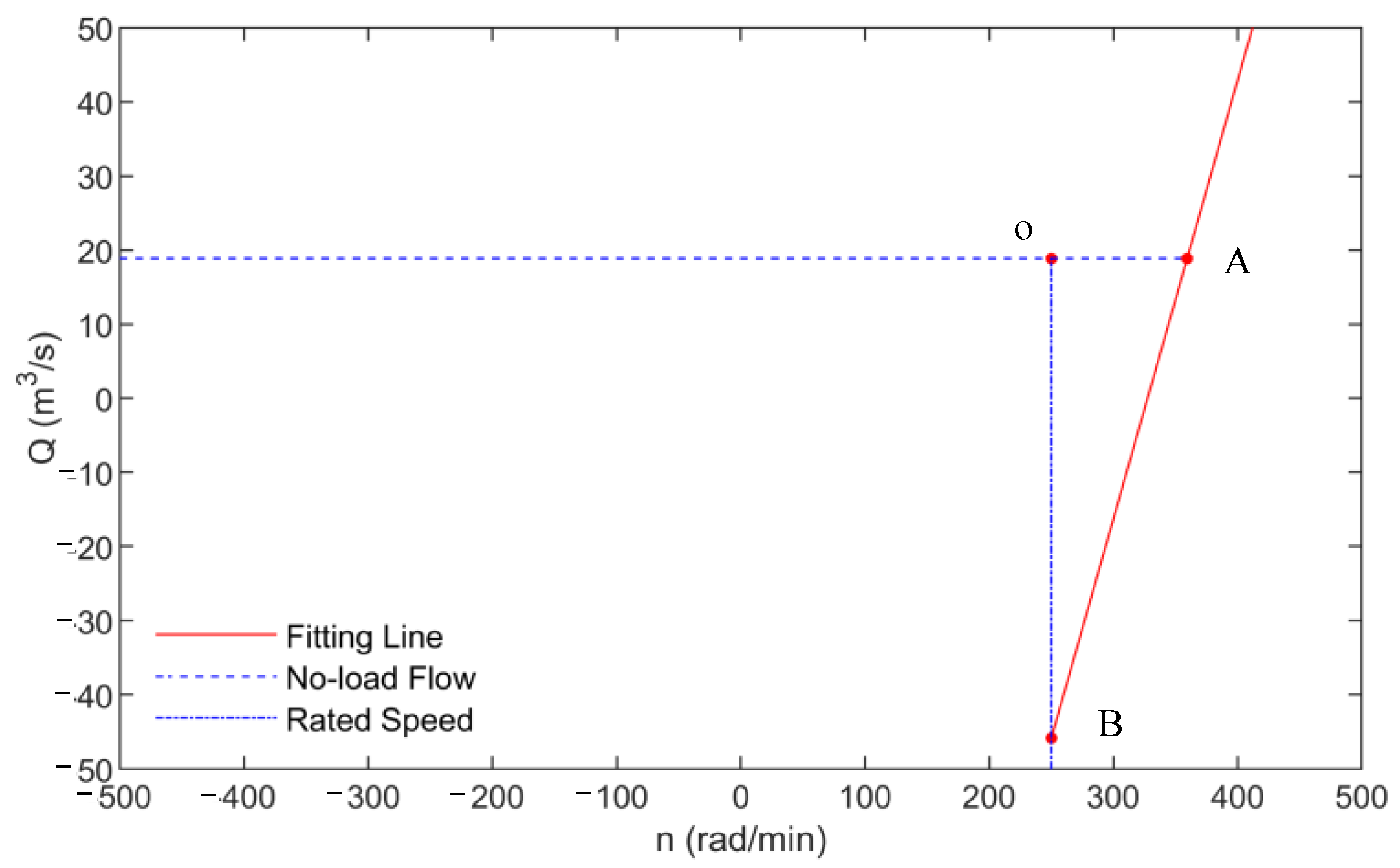
Considering the large order of magnitude difference between unit speed and unit flow, in order to improve the accuracy of describing the positional relationship between the no-load operating point of the PSU and the SFR, use Equations (14) and (15) to convert the straight line in
Figure 5 into the straight line in
Figure 6.
It can be seen from
Figure 6 that the ratio of the relative value between the distance OA from the no-load operating point O entering the SFR along the no-load flow line and the rated speed and the relative value between the distance OB from the no-load operating point O entering the SFR along the rated speed line and the no-load flow is
Therefore, when the PSU is started, it will enter the SFR of the pump turbine between AB and near point A. Thus, the direct cause of SFR entry is the speed overshoot when the PSU is started. The critical speed overshoot is .
4.2. Critical Stability States of Pumped Storage Units
When the PSU is initiated and engaged in PID control, if the system does not converge and the speed continues to increase, it will definitely enter the SFR for operation. If the system converges and the speed overshoot is less than the critical overshoot, the operation can avoid the SFR. Therefore, the critical stability of the system and the speed overshoot is equal to the critical overshoot, which is the critical state for the PSU to enter the SFR.
The stability of the nonlinear pumped storage unit governing system can be studied using Hopf bifurcation theory.
(1) The equilibrium point of the system
The nonlinear pumped storage unit governing system expressed in (7) can be transformed into a general nonlinear differential equation , and the equilibrium point of the system can be obtained as from .
(2) The condition of Hopf bifurcation
The Jacobian matrix of system
at equilibrium point
can be expressed as
where
; ; ; ;; ; ; ; ; ; ; ; ; .
The characteristic equation of the Jacobian matrix can be expanded as
where
;
;
;
.
The conditions for generating Hopf bifurcation in the system are as follows:
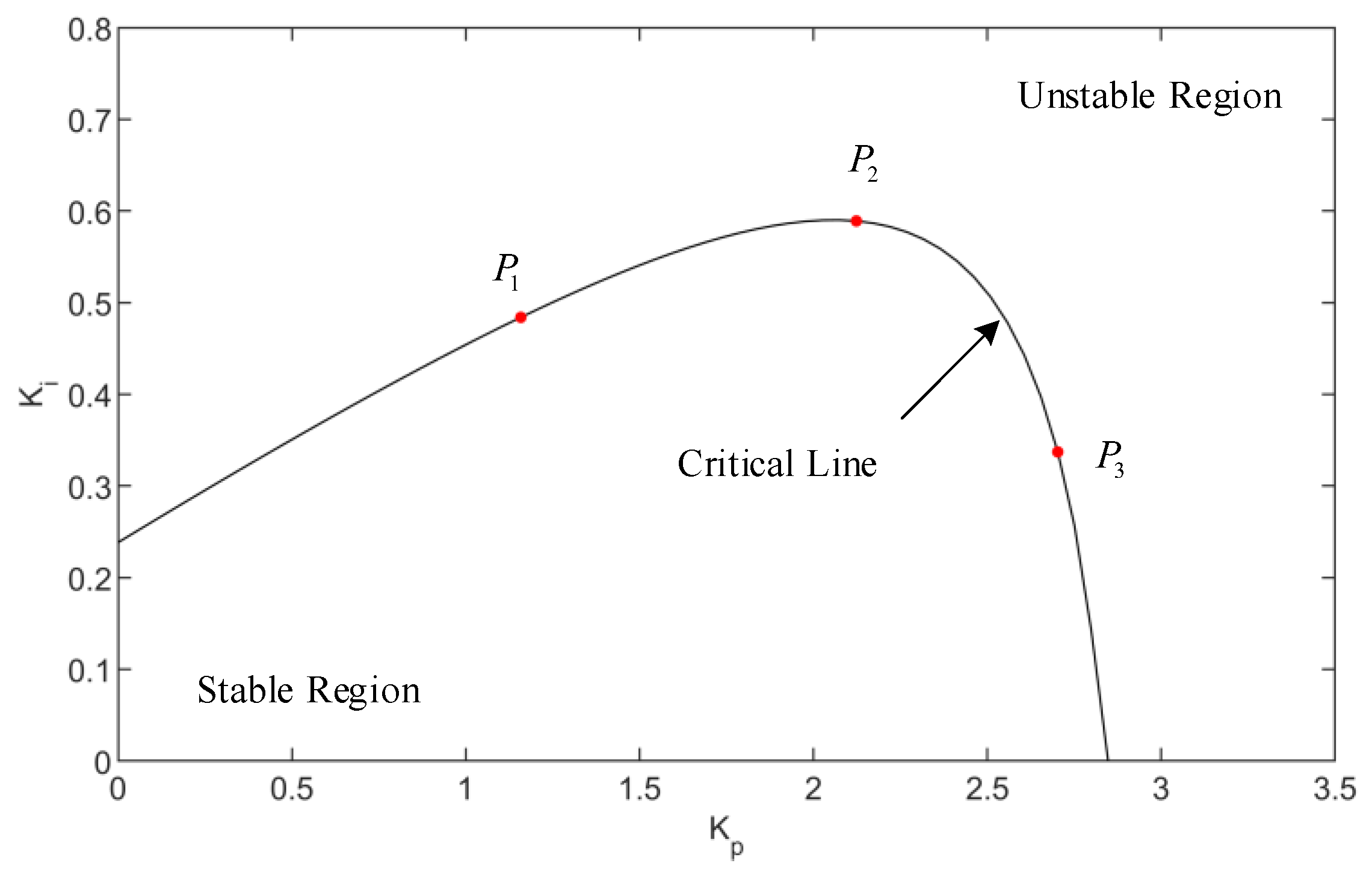
If
is regarded as the bifurcation parameter
, the stability region of the system can be drawn from the
parameter plane, where
is taken as the abscissa and
as the ordinate. The stable region of the system can be drawn according to Equations (20)–(22), as shown in
Figure 7.
To verify the correctness of the mechanism of avoiding the SFR when the PSU starts up with no load obtained in
Section 4.1 and study the critical state of the PSU entering the SFR, take three control parameter points
,
, and
from the critical line, respectively, in
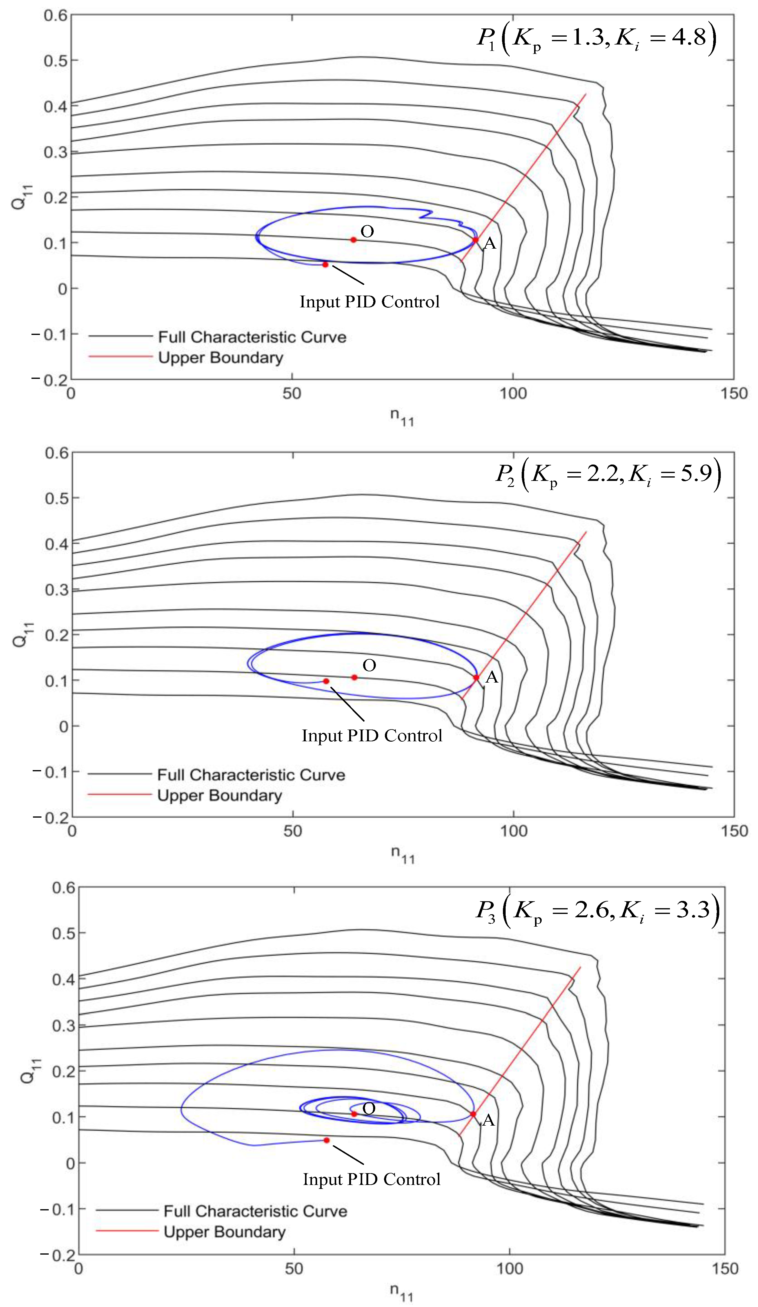
Figure 7 for dynamic simulation. When the unit speed reaches 90%, the PID controller is activated to regulate the flow, bringing the PSU into the critical state of the SFR as shown in
Figure 8.
It can be seen from
Figure 8 that if the PSU is in a critical stable state and the maximum speed overshoot is equal to the critical overshoot, the unit is in a critical state to enter the SFR and enters from operation point A near the upper boundary of the SFR.
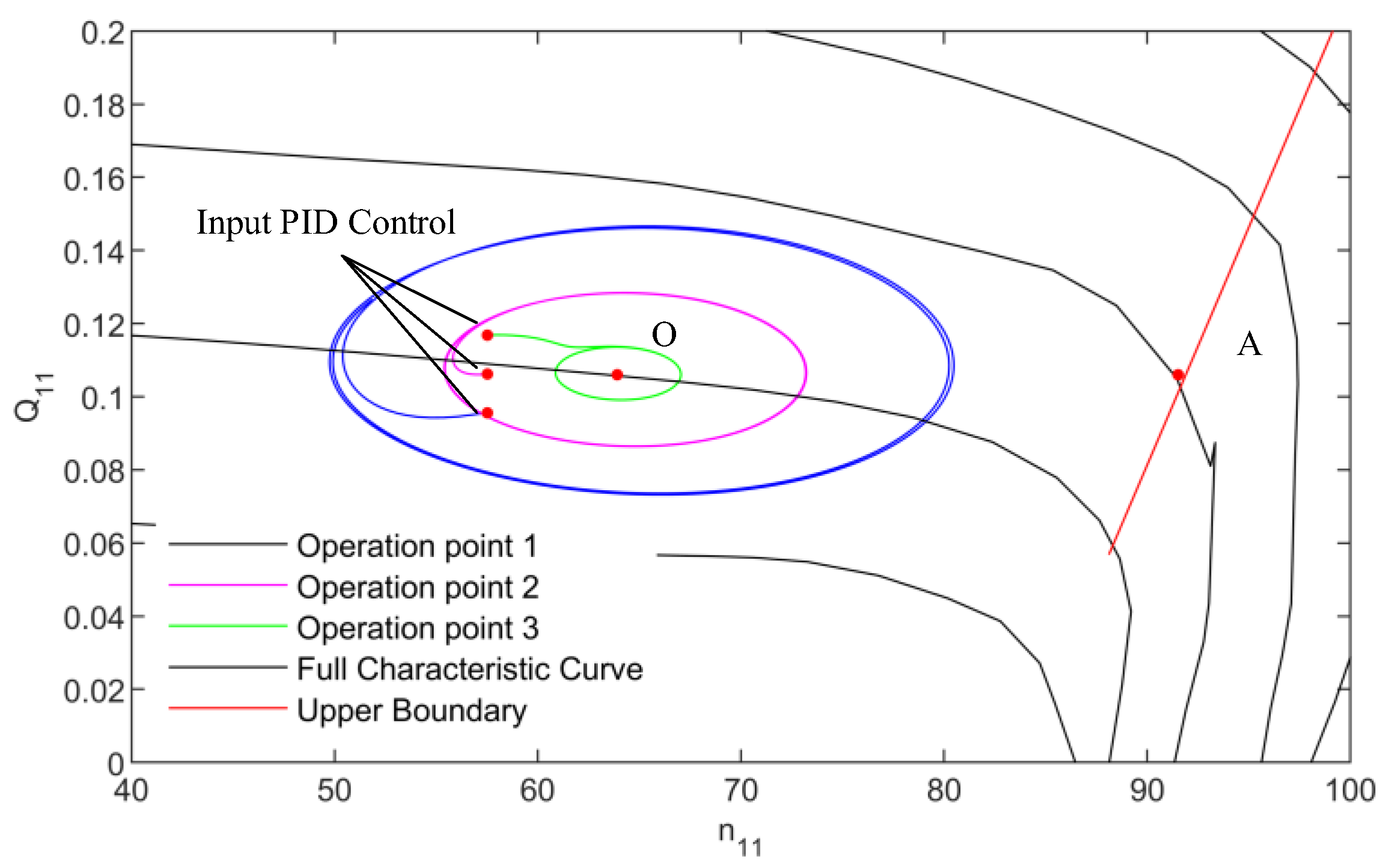
4.3. Influence of the Operation Point on Stability When Putting in PID Control
When the PSU is started, PID control is generally added at 90% of the rated speed. To study the influence of the operation point on the stability of the system when PID control is input, three operation points with different flow rates (the opening of the guide vane is also different) when the unit reaches 90% of the rated speed are studied. The initial states of the three operation points are as follows:
Operation point 1: , ;
Operation point 2: , ;
Operation point 3: , .
It can be seen from
Figure 9 that, after the system input PID control, the trajectory of the full characteristic curve is a limit circle, which also proves the correctness of the Hopf bifurcation analysis above. Among them, the radius of the limit circle generated by the operation point with the large flow is smaller after the PID control is put into operation, that is, the smaller the maximum amplitude of the system is.
5. Conclusions
This study addresses the challenge of low-head starting failures in pumped storage units, which occur when the unit enters the SFR during startup. To ensure safe startup, an active strategy for dynamically avoiding this region was developed. By establishing a mathematical model of the SFR’s upper boundary for the pump turbine and employing geometric analysis, the research revealed a critical spatial relationship between the unit’s no-load operating point and this boundary. Stable startup is achieved only when the no-load point resides above the SFR’s upper boundary, enabling the unit to bypass the region. Conversely, instability in the characteristic curves occurs when the no-load point lies below the boundary, leading to startup failure. The main conclusions are as follows:
(1) Two conditions need to be met to avoid the SFR during the no-load start-up of PSUs—one is that the system parameters are within the stability domain, and the other is that the maximum overshoot of the unit speed is less than the critical overshoot.
(2) When the PSU is started, the speed overshoot is the direct reason for entering the SFR. When the PSU is put into PID control at 90% speed, the speed overshoot should be strictly controlled within the critical speed overshoot.
(3) When the PSU is started, the PSU is put into PID control at 90% speed, and a certain guide vane opening and flow margin should be reserved; that is, the guide vane opening is slightly greater than the no-load opening, and the flow is slightly greater than the no-load flow.
This study analyzed the spatial relationship between no-load operating conditions and S-shaped boundaries, quantified the conditions for avoiding the SFR during PSU startup, and provided a new perspective on the prevention and control of PSU startup instability.
However, the strong nonlinearity and time-varying characteristics of actual unit models still pose technical bottlenecks in dynamic boundary identification, strong coupling control optimization, and extreme operating condition adaptability. To ensure engineering reliability, a sufficient stability margin should be reserved to cope with model uncertainty when applying bifurcation principles to identify the approaching critical state of the operating point.
Future research will gradually advance along the path of “simulation pilot iteration”: by integrating intelligent algorithms to optimize boundary adaptive capabilities, overcome the bottleneck problems mentioned above, and ultimately achieve the engineering implementation of control strategies. This achievement not only provides a new understanding of the instability mechanism during the start-up of PSUs but also offers a universal reference for the transient process control of similar hydraulic machinery through its geometric obstacle avoidance concept and critical state quantification method.


