Article

Wear Testing and Anti-Wear Performance Analysis of Surface Coating Materials for Stay Vanes of a Francis Turbine

1
Key Laboratory of Fluid and Power Machinery, Ministry of Education, Xihua University, Chengdu 610039, China
2
College of Water Resources and Civil Engineering, China Agricultural University, Beijing 100083, China
3
Yingxiuwan HydroPower Plant, State Grid Sichuan Electric Power Company, Chengdu 611830, China
*
Authors to whom correspondence should be addressed.
Water 2025, 17(11), 1671; https://doi.org/10.3390/w17111671
Submission received: 6 May 2025 / Revised: 27 May 2025 / Accepted: 28 May 2025 / Published: 31 May 2025
(This article belongs to the Section Hydraulics and Hydrodynamics)

Abstract

The wear of the flow passage components of the turbine due to sediment in sandy rivers is an inevitable challenge for hydroelectric units, often requiring frequent maintenance of hydraulic turbines. Consequently, the anti-wear protection technologies of hydraulic turbine components have garnered significant attention. In this study, three coating materials were analyzed for the stay vanes of the Francis turbine commonly used in hydropower stations. These materials, including JX ceramic metal wear-resistant material (JX33083), 3D printing additive manufacturing cermet material, and Foshilan polymer material, were tested for sediment wear, and their anti-wear performance was evaluated. The research results indicate that the anti-wear performance of the three coating materials is almost identical when the velocity on the surface of the stay vanes is below 7.5 m/s. Notably, 3D printing additive manufacturing cermet material demonstrates the best anti-wear performance when the velocity exceeds 7.5 m/s. The anti-wear effect of this coating material is 3.27 times more wear-resistant than Foshilan polymer material and 6.39 times more wear-resistant than JX ceramic metal wear-resistant material. Hence, these research findings provide a technical basis for the selection, operation, and maintenance of anti-wear coatings for the stay vanes of turbines in hydropower stations.

1. Introduction

Hydropower is one of the vital aspects of energy infrastructure. As the core equipment of hydropower stations, turbines experience inevitable wear of the flow passage components in sandy rivers due to sediment, presenting a persistent challenge for hydroelectric units [1]. The hard particles carried in the water flow cause erosion and abrasion on the flow passage components of the turbine, gradually cutting and peeling their surfaces and leading to surface material loss. Ultimately, this results in the formation of destructive morphology, such as grooves and fish-scale pits, on the component surface [2]. Moreover, the issue of sediment erosion in turbines has drawn significant attention from scholars and engineers. Besides the research on the mechanism of sediment wear, researchers are increasingly focused on anti-wear coating research on the flow passage components of turbines, aiming to extend the service life of these components and ensure the efficient and stable operation of hydropower station units.
Based on the characteristics of epoxy coating and polyurethane elastic coating, Li Qingfeng et al. [3] proposed three different coating protection schemes and applied them to the stay vanes of the turbine at the Fuchun River Hydropower Station. To explore the cavitation and wear characteristics of the materials, Zhang L et al. [4] conducted cavitation and wear tests on 45 # steel substrate, epoxy mortar, composite resin mortar, and polyurethane guide vanes; established the wear rate prediction models; and predicted the service life of the materials under strong cavitation. Liu Ya-jun et al. [5] developed a novel polymeric metal mixture to repair the cavitation areas on the surface of the flow passage components of the turbine and applied an anti-corrosion coating spraying treatment to address the cavitation issue of the stay vanes. To address the issue of severe wear on the flow-through components of the turbine at the Shangmati Hydropower Station, Li Songsen et al. [6] adopted anti-wear spray materials and technologies to apply thermal spray anti-wear coating materials to the flow passage components of the turbine, improving the anti-wear performance of the flow passage components and achieving remarkable results. To analyze the cavitation and abrasion performance of three non-metallic anti-wear coatings, Wang Lei et al. [7] conducted experiments addressing the erosion and damage of the guide vanes of turbines in rivers with high sediment. According to the test results, the polyurethane coating exhibited the best cavitation resistance, while the composite resin mortar and polyurethane demonstrated the best abrasion resistance. Wang Y et al. [8] conducted a sediment wear test on the flow passage components coated with epoxy mortar materials, with the test results revealing that the wear of the epoxy mortar coating material was minimally sensitive to coating thickness. Furthermore, based on the results of the sediment wear test and the numerical simulation of sand and water, an estimation formula for the sediment erosion rate of the epoxy mortar anti-erosion coating was established. Yao B. et al. [9] conducted a sediment wear test on blades coated with tungsten carbide, established the wear prediction model, and analyzed the influence of tungsten carbide coatings on the wear resistance of runner blades. Additionally, Singh H. et al. [10] cold-sprayed various types of tungsten carbide (WC) coatings on turbine base steel (CA6NM) and analyzed the microstructure of the coatings using scanning electron microscopy (SEM) and X-ray diffraction (XRD). Moreover, the cavitation erosion performance was assessed using an ultrasonic vibration tester, demonstrating the potential of cold-sprayed WC-based coatings in protecting turbine steel from erosion. Pandey A. et al. [11] used flame spraying and high-speed oxygen fuel (HVOF) coating technologies to develop ceramic and metal–ceramic protective coatings for the flow passage components of turbines. According to the study, the metal–ceramic coatings generally exhibited better anti-wear performance due to the composite shielding effect of ceramics and metals and the reduction in impact energy. Kashyzadeh R. K. et al. [12] examined the influence of different nano-coatings on the material properties of the runner of turbine 304 and 316 L steel, emphasizing the advantages of this anti-wear coating technology over traditional coatings. Furthermore, they discussed the influence of single-layer and multi-layer coatings with different compositions on the corrosion, wear, and erosion properties of each type of stainless steel. Hassan E. et al. [13] explored the potential of applying epoxy resin anti-corrosion coatings on tidal turbines to resist erosion effects in environments with and without granular seawater. Furthermore, they evaluated the effect of the coatings through a series of tests and assessed the durability of epoxy resins and the potential uses of the coatings in the tidal turbine blade industry. Bolelli G. et al. [14] used the supersonic flame spraying technology to apply the WC10Co4Cr coating on the surface of the runner steel and conducted wear tests on it. According to the test results, this coating material can effectively avoid cavitation and wear damage, improving the service life of the blades. Abhishek B. et al. [15] analyzed the anti-wear performance and anti-cavitation properties of the WC10Co4Cr coating developed by the detonation spraying technology through deep cryogenic treatment (DCT) and found that the anti-wear performance of the coating after DCT was 1.5 to 4.2 times higher than that before spraying, and the anti-cavitation property was 1.6 times higher. Abgottspon A. et al. [16] conducted a study on the wear characteristics of the HPP Fieschertal coating and applied it to the impulse turbine for a wear test. The results demonstrated that the coating improved efficiency and achieved better anti-wear performance.
Notably, the Francis turbine is a commonly used model in hydropower stations. Although its flow passage components typically have a relatively low flow velocity, their long-term operation on sandy rivers can cause severe wear. Currently, the majority of repair methods involve applying protective coatings on its surface. The wear resistance of the coatings determines the safety and economy of the hydropower station. In this study, sediment wear tests were conducted on three coating materials, namely JX ceramic metal wear-resistant material (JX33083, From Chongqing Jiexiao Technology Co., Ltd., Chongqing, China), 3D printing additive manufacturing cermet material (From Chengdu Tianfu New Area Hechuan Technology Co., Ltd., Chengdu, China), and Foshilan polymer material (From Harbin Xingdeli Technology Co., Ltd., Harbin, China), for the stay vane component of the hydropower station’s Francis turbine, and their anti-wear performances were analyzed. The findings of this study provide the technical basis for the selection, operation, and maintenance of anti-wear coatings for the stay vanes of the turbine in hydropower stations.

2. Principle and Test Method of Sediment Wear Test

2.1. Test Principle

The sediment wear test of the turbine is performed by the flow around the flow passage components of the turbine. The test principle involves using the flow of sand–water to scour the specimens of the flow passage components of the turbine under a specific system pressure, causing wear on the specimens. Based on the numerical calculation results of the sand–water flow in the actual turbine, the flow channel containing the wear test flow specimens is extracted to design the sediment wear test device. The geometric and flow similarity between the test flow specimens and the actual turbine is maintained in the design of the flow channel of the test specimens and their test section.

2.2. Test Method

The degree of wear of the specimens was determined using the depth measurement method. The wear depth value was obtained using the white light interferometer, which measures the morphology and depth of the specimens’ surface before and after wear at the test position. Figure 1 and Figure 2 display the white light interferometer and its test method, with a measurement accuracy of up to 0.1 nm. The height difference, ΔZ = Z1 − Z2, before and after wear, represents the wear depth at the test position of the specimens’ surface under the test conditions. Figure 3 illustrates the test data diagram of the stay vane specimen at the test position. Notably, the wear of the sand–water flow in this area is significantly affected by the geometry of the side wall of the box due to the side wall effect of the box on the upper and lower ends of the stay vanes, considerably affecting the measurement accuracy. To obtain the accurate wear depth, the surface measurement value near 50% of the stay vane height is generally taken, such as the range of 15 to 25 mm (40% to 60% vane height, the pink area) illustrated in Figure 3.

3. Sediment Wear Test Device and Specimen Production

In this study, the HLA542 turbine (From Harbin Electric Group Co., Ltd., Harbin, China) of Yuzixi Hydropower Station was chosen as the research object. Table 1 displays the basic design parameters of the turbine. The relevant information of the selected coating materials is as follows: JX ceramic metal wear-resistant material (JX33083) is a composite material composed of ceramic alloy, polymer active heavy polymer, and low polymer. It is characterized by high wear resistance and corrosion resistance, making it suitable for the impact wear of flow passage components like turbine stay vanes. The 3D printing additive manufacturing cermet material is processed and manufactured using improved formula materials and a micro-droplet ion sputtering process. It is primarily used in components such as stay vanes, guide vanes, and runner blades of turbines that are vulnerable to sediment wear and cavitation damage. The Foshilan polymer material consists of EH503 metal repair and protection composite material and EH512 self-leveling polymer ceramic composite material. It is characterized by good wear resistance, high-temperature resistance, and chemical corrosion resistance. It is often used to repair and protect various worn turbine vanes and runners.

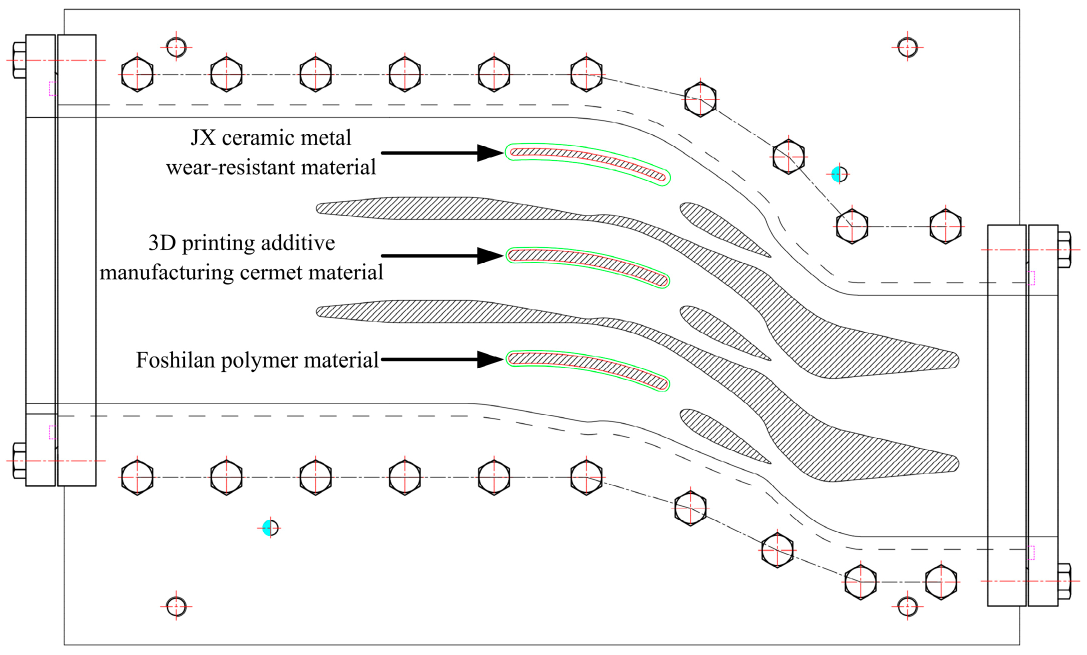
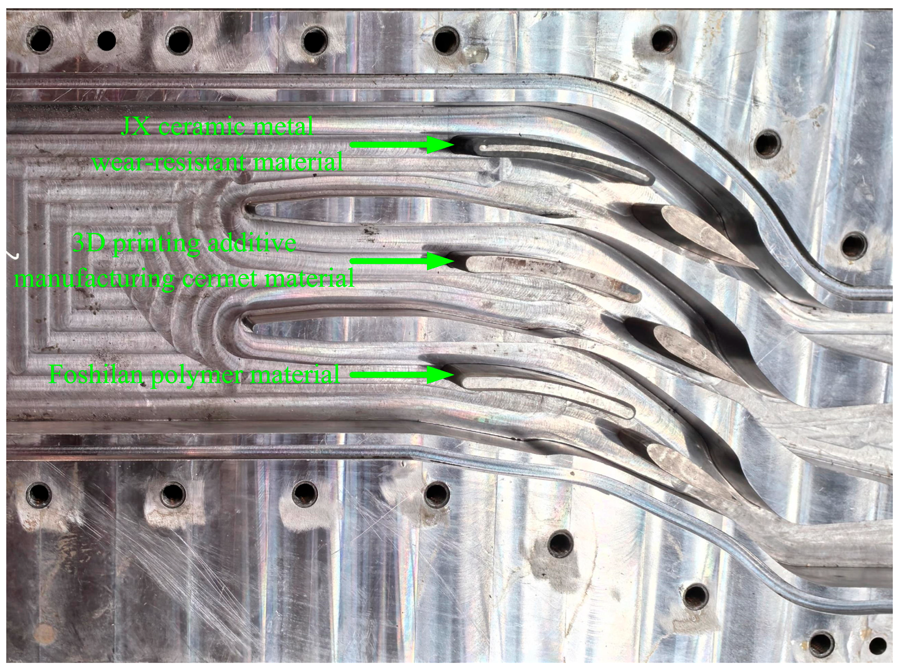
3.1. Design of Test Device

As shown in Figure 4, the internal velocity cloud diagram of the distributor and the streamlines within the test device were obtained based on the numerical calculation results of the sand–water flow in the turbine at the Yuzixi Hydropower Station under rated conditions [17]. The sediment wear test device was designed based on the extracted streamlines, ensuring that the wall shape of the test device matched that of the actual turbine streamlines.
The wall of the test device was designed based on Streamline I and Streamline II, with the length of the inlet and outlet adjusted appropriately to avoid the occurrence of backflow. Moreover, the size of the test section of the stay vane specimens and their single channel was reduced to 1/3 of the actual machine due to the sediment wear test in the laboratory. Figure 5 displays the design structure of the single channel.
To study the anti-wear performance of three different coating materials on the surface of stay vanes, a design method of a three-channel test section was proposed based on the structure of a single-channel test device extracted from Figure 5. The test section was composed of three independent single channels side-by-side splicing, and the solid walls were set in the middle for separation, thus forming a complete three-channel test section. Figure 6 displays the box section processing diagram of the test section. The stay vane specimens coated with coating materials were arranged in the following order: JX ceramic metal wear-resistant material, 3D printing additive manufacturing cermet material, and Foshilan polymer material. The box is made of a Q35B metal block using numerical control technology. The stay vane specimens were installed in the groove at the bottom of the test section box following the completion of the production. Figure 7 presents the physical diagram of the test section box after installation.

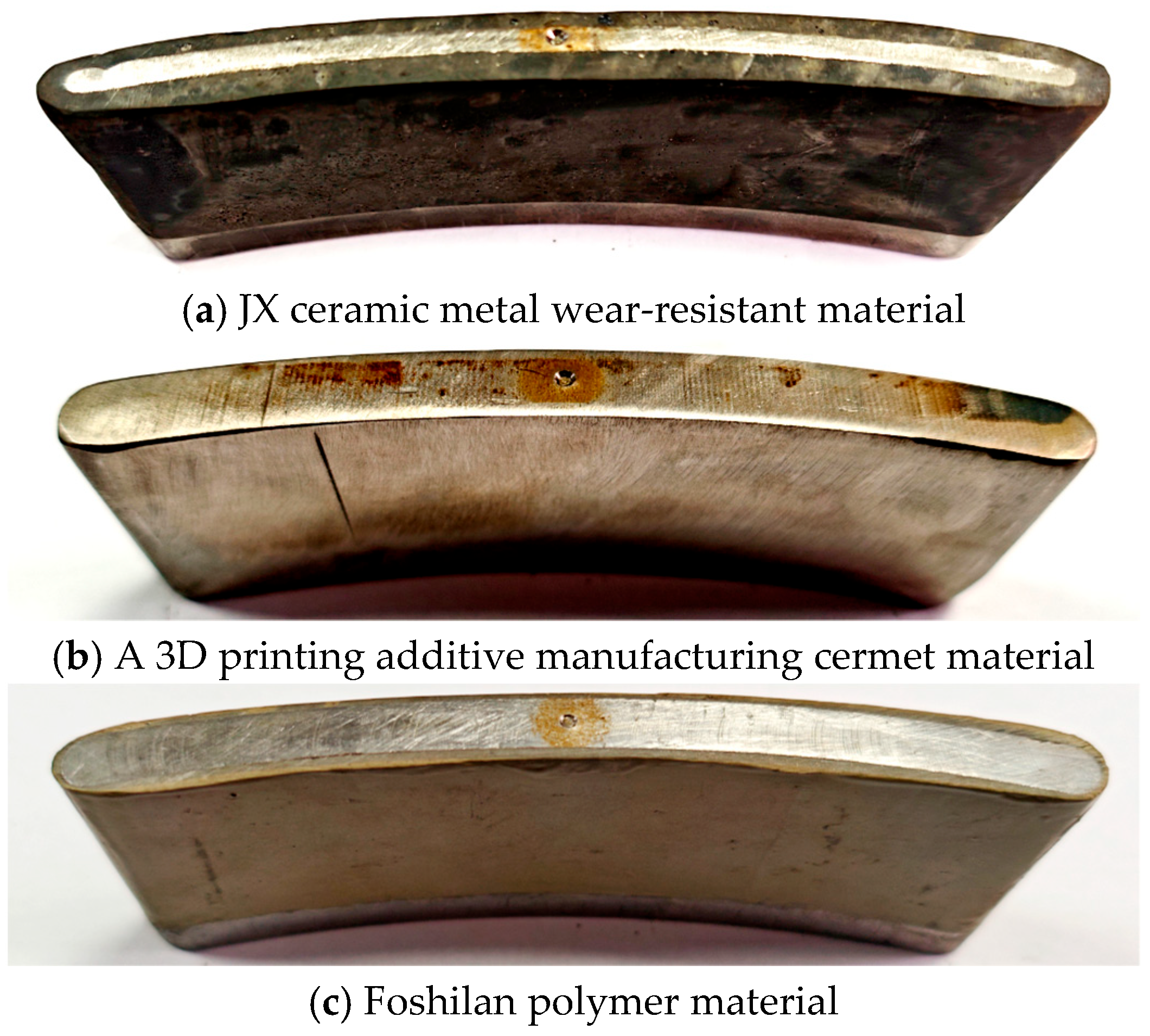
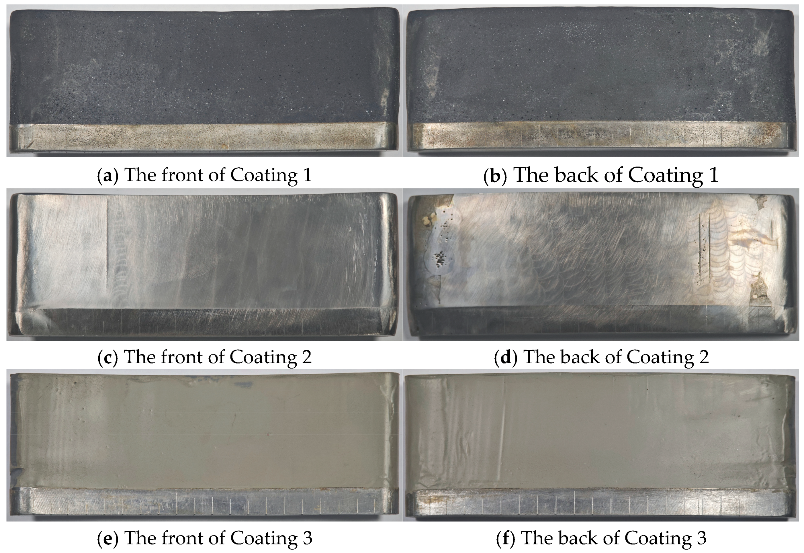
3.2. Specimen Making

The base material of the stay vane specimens was precision machined using CNC technology on 15MnTi metal blocks. Subsequently, the coating materials were coated on the surface of the stay vane specimens through thermal spraying and smearing technology, and the stay vane specimens, coated with 2 mm coating material, were obtained, as depicted in Figure 8.

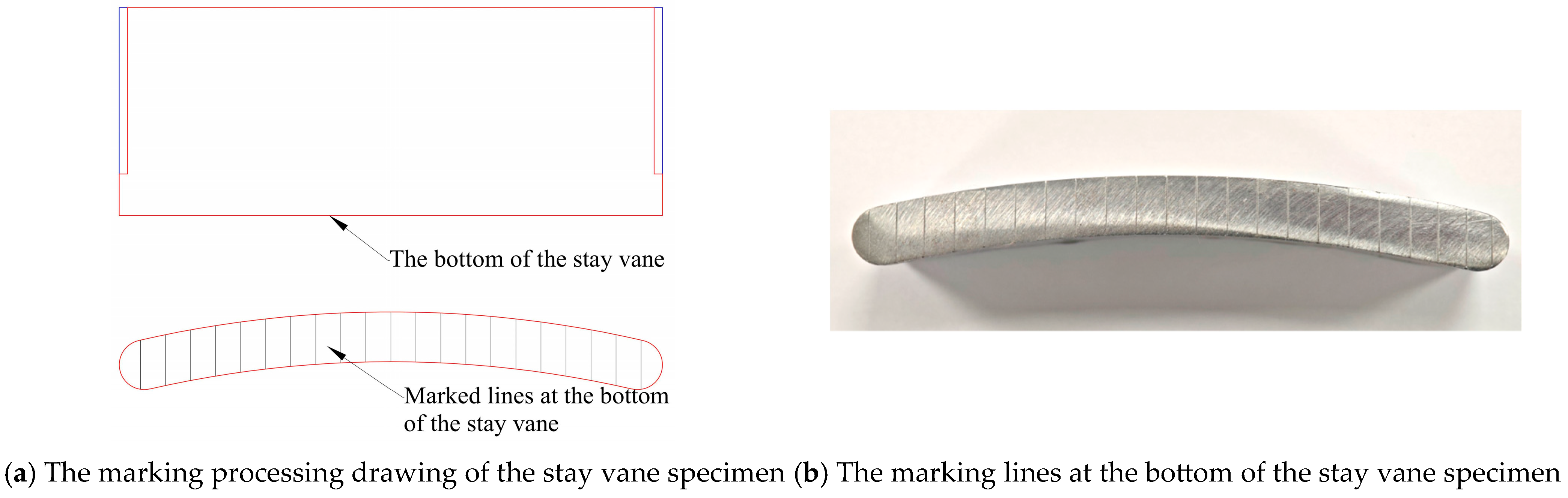
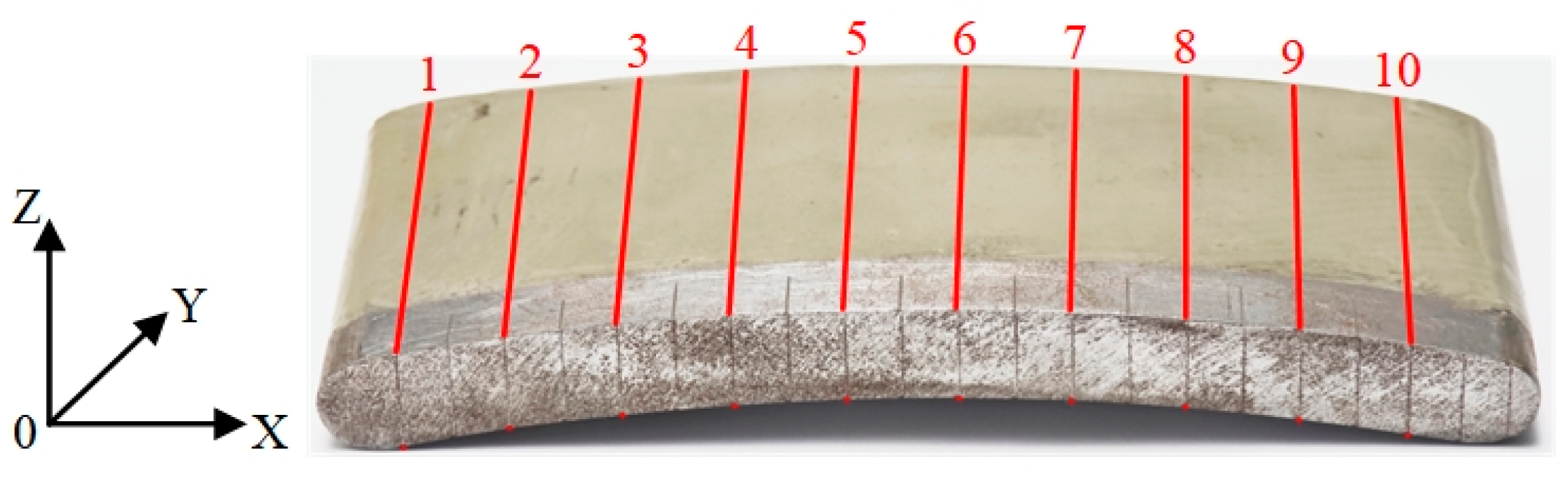
3.3. Specimen Test Positioning Mark

As depicted in Figure 9, after the stay vane specimens are made, it is necessary to mark the positions on their surfaces to be tested according to the selected white light interferometer testing method. To ensure accurate testing of the morphology and depth data of the same position before and after the sediment wear test, the bottom end faces of the stay vane specimens were marked with lines. In the test section structure, the length of 10 mm at the bottom of the specimens was embedded in the groove at the bottom of the test section box. During the test, this 10 mm long part does not participate in sediment wear, which serves as a reference to compare the wear depth at the same position before and after wear.
The spatial test position of the stay vane specimens was determined based on the coordinates of Figure 10: the X-axis is along the chord direction of the stay vane, the Y-axis is along the height direction of the stay vane surface, and the Z-axis is along the thickness direction of the stay vane. The testing of the specimens was conducted along the Y-axis of the stay vane height. The numbers 1 to 10 in the figure represent the number of marked lines.

3.4. Construction of Sediment Wear Test System

According to the designed sediment wear test device, the constructed sediment wear test system primarily consisted of the power system, sediment mixing system, cooling system, and test device system, which included a test section box and test specimens. The maximum power of the power system is 630 kW, the pressure of the test system is 376 m, and the rated flow is 320 m3/h. Figure 11 presents the sediment wear test system of the hydraulic turbine.

4. Sediment Wear Test

4.1. Wear Test Parameters

The base material of the stay vanes is 15MnTi, and the surface is coated with three anti-wear coating materials: JX ceramic metal wear-resistant material (Coating 1), 3D printing additive manufacturing cermet material (Coating 2), and Foshilan polymer material (Coating 3). The sediment was collected on-site from the Yuzixi section of the Minjiang River Basin. The sediment wear test was performed in the laboratory based on the average sediment content of 3.0 kg/m3 at the station over several years. Table 2 presents the particle size gradation of suspended sediment samples in the river.

4.2. Test Results of Sediment Wear

Notably, the inlet flow rate of the test system was 320 m3/h, and the sediment content was 3 kg/m3. The sediment wear test was conducted on the stay vane specimens coated with three different materials for 100 h. Figure 12 depicts the wear conditions of the stay vanes of different anti-wear coating materials following the wear test.

4.3. Sediment Wear Test Results

The surface depth and wear amount at the marked test positions before and after the sediment wear test were measured using a white light interferometer on the stay vane specimens coated with different coating materials. The measured surface depth and wear amount data were extracted into post-processing software, and the wear condition is shown in Figure 13. Moreover, as shown in Figure 14, the difference in surface depth before and after wear determines the wear amount of the specimen surface.

5. Analysis of Anti-Wear Performance of Anti-Wear Coating Materials

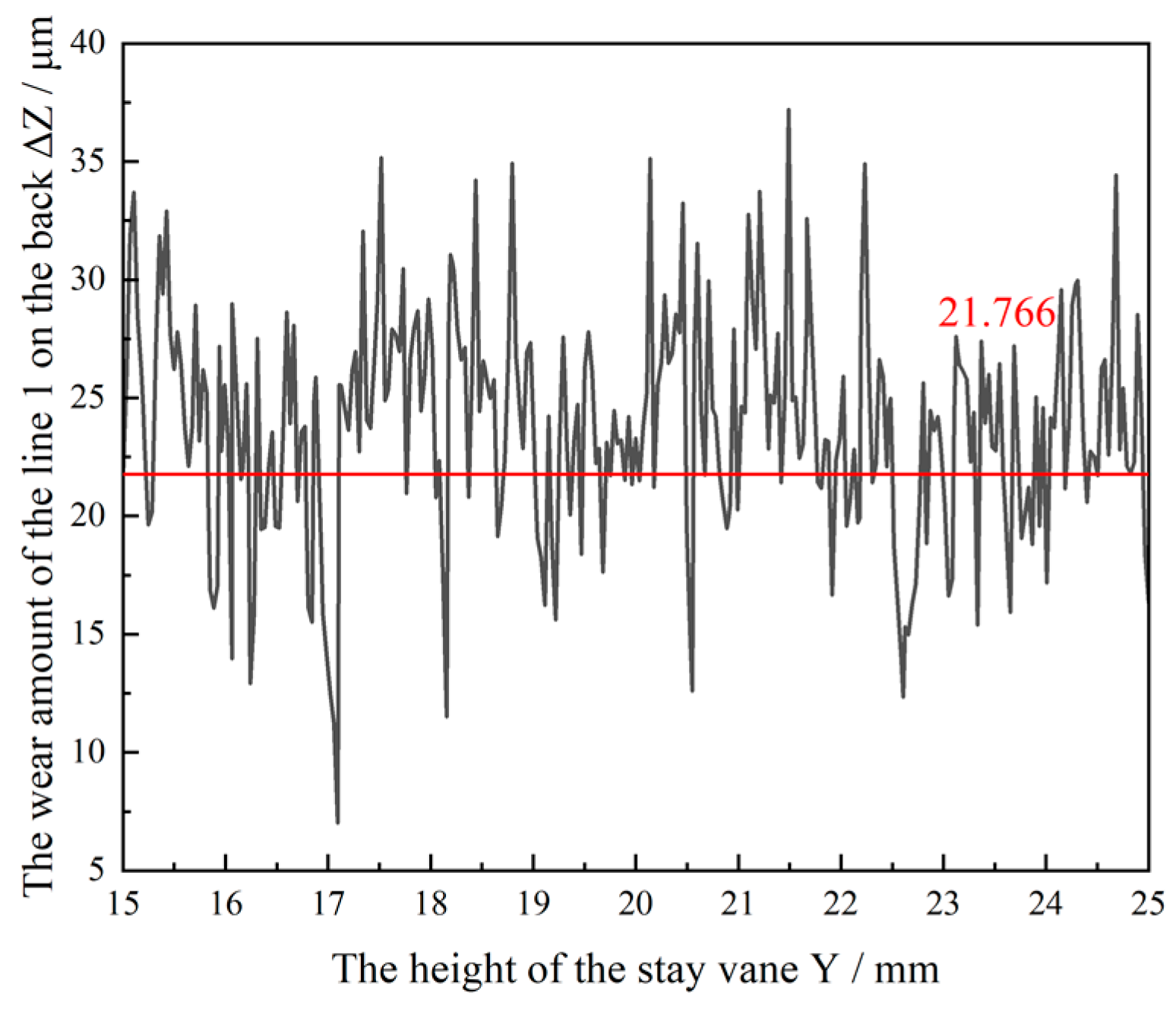
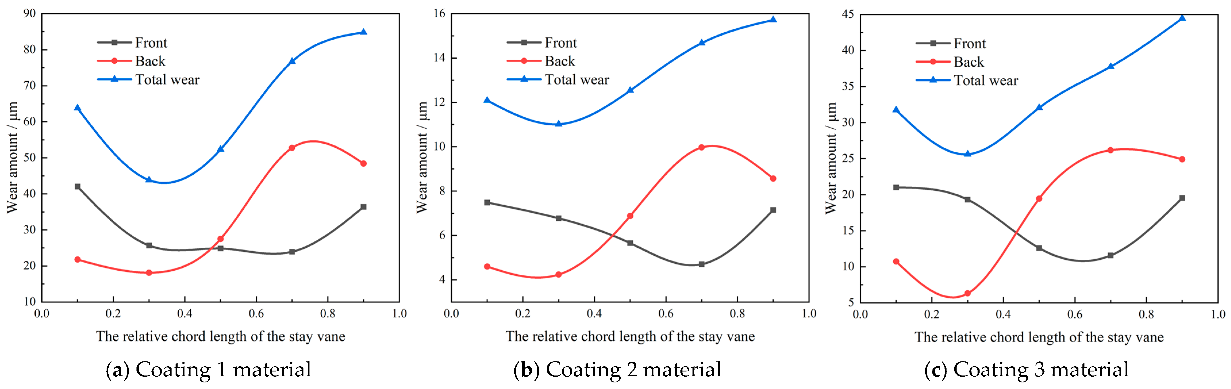
5.1. Wear Distribution of Specimens

As depicted in Figure 15, the wear distribution of the cross-section of the 50% vane height of the stay vane specimens coated with different coating materials was obtained using the white light interferometer.
Figure 15 reveals that the stay vane specimens coated with the three coating materials exhibit different surface wear amounts after 100 h of sediment wear erosion. Among these, the stay vane specimen coated with Coating 2 exhibited the least wear, with wear amounts on both the front and back sides being less than 10 μm. The stay vane specimen coated with Coating 1 exhibited the largest wear, with the maximum wear amount of approximately 55 μm at the tail end of the back of the specimen.

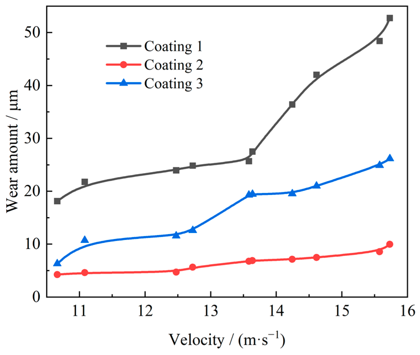
5.2. The Relationship Between Flow Velocity and Wear Amount

Herein, the flow velocity around the test positions of the specimens was obtained based on the numerical calculation results [17]. Furthermore, the relationship between the flow velocity and the wear amount of different coating materials was obtained based on the wear amount at the test positions. Figure 16 depicts the relationship curves between the flow velocity and the wear amount of different anti-wear coating materials.
The relationship between the flow velocity and the wear rate of different coating materials on the surface of the stay vanes can also be obtained by dividing the wear amount observed in Figure 16 by the test time of 100 h. Subsequently, the velocity and wear rate at each test position were nonlinearly fitted in the post-processing software, resulting in the fitting curves of the flow velocity and the wear rate of different anti-wear coating materials, as depicted in Figure 17.

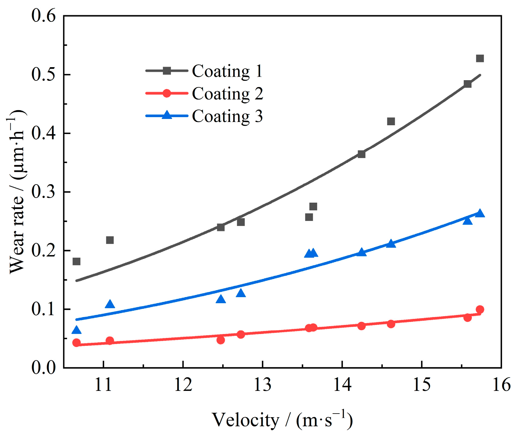
5.3. Establish Wear Model (Calculation Formula)

After completing the sediment wear test, the sediment wear rate calculation formula of different coating materials was established for the turbine operating on a given sediment-laden river, provided that the sediment characteristics of the river, the turbine model, and the material of the turbine flow components are known. The sediment wear rate calculation formula was obtained based on the test results, and the wear of the coating material on the surface of the stay vane under various working conditions can be predicted.
The general expression for the sediment wear of turbine flow passage components [18] is as follows:
E ˙ = k 0 k s k m C V m W n
In the formula, Ė represents the wear depth of the surface material of the flow passage components in unit time, μm/h; ks denotes the influence coefficient of sediment particles; km represents the material influence coefficient of the flow components; k0 denotes the other influence coefficient besides ks and km, which include the impact angle of sediment particles, and the local concentration distribution on the surface of the flow components. CV denotes the sediment concentration at the inlet of the turbine, kg/m3, and the sediment concentration index m is generally 1 in the river; W represents the velocity of sediment flow on the surface of the flow component, m/s; n signifies the velocity index.
The sediment concentration CV = 3 kg/m3 of the experimental device examined in this paper is determined, and the characteristics of the sediment and stay vane material are also determined. Therefore, for a given river sediment concentration, assuming the influence of k0 is neglected, the sediment wear formula of Equation (1) can be simplified as follows:
E ˙ = K W n
Based on the numerical calculation results of the sand–water flow [17] and the results of the sediment wear test, the wear calculation formulas and coefficients of different materials coated on the surface of the stay vanes of the turbine can be obtained by nonlinearly fitting the flow velocity and wear rate of each test position in the post-processing software (see Table 3). Meanwhile, Figure 17 shows the fitting curve of the flow velocity and wear rate of different coatings.
As indicated in Figure 18, the wear rate curves of the three coating materials are almost identical when the velocity on the surface of the stay vane is less than 7.5 m/s, indicating that the difference in their wear resistance is minimal, irrespective of the type of coating material selected at this stage. Notably, the wear rate curves of the stay vanes of the three coating materials begin to show significant differences when the velocity on the surface of the stay vane exceeds 7.5 m/s. Moreover, the wear rates of Coating 1 and Coating 3 increase rapidly with increasing flow velocity, and the wear rate gap with Coating 2 gradually widens. The wear rates of the three coating materials are ranked from low to high as follows: Coating 2, Coating 3, and Coating 1. Coating 2 exhibits the best anti-wear performance, while Coating 1 presents the worst performance. It must be noted that the anti-wear performance of Coating 2 differs significantly from that of the other two materials. Furthermore, the numerical calculation results [17] reveal that the velocity of sediment around the front and back of the stay vanes is generally less than 20 m/s, neglecting the high-speed situation formed by the impact of water flow in the head area of the stay vane. Therefore, it is recommended to use Coating 2 material, which has the best anti-wear performance on the surface of the stay vane.

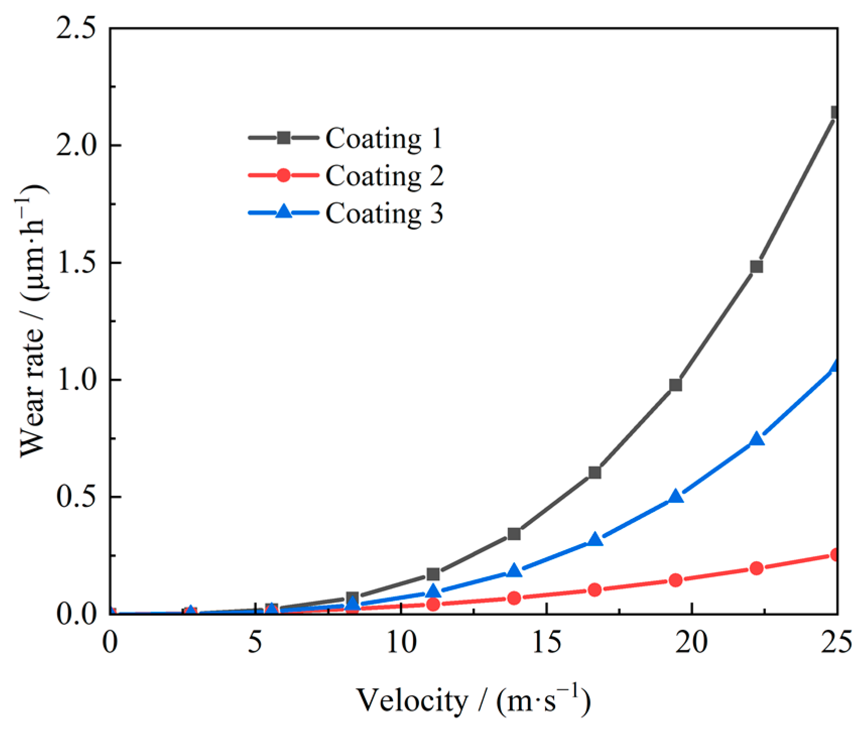
5.4. Wear Prediction

Different coating materials of the stay vanes of hydraulic turbines operate under different working conditions and different sediment concentrations. The wear depth ΔZ at different positions of the stay vanes is cumulatively estimated using Equation (3).
Δ Z = E ˙ i t i
In the formula, ti denotes a certain period of running time; Ėi represents the wear rate within the operating time ti.
For the Yuzixi Hydropower Station, the annual average sediment content is CV = 3 kg/m3, and the maximum sediment flow velocity on the surface of the stay vanes is 18.35 m/s. The time required for different coating materials to wear down by 2 mm can be obtained using Equation (3), and this time length is regarded as the wear life of the coating material. Notably, the power station determines the specific time for the maintenance of the unit based on these data. Furthermore, it can be determined that the turbine of Yuzixi Hydropower Station operates under rated conditions. Notably, the wear amount of the coating material on the surface of the stay vane reaches 2 mm after approximately 2451 h of continuous wear for Coating 1, approximately 15,657 h for Coating 2, and approximately 4785 h for Coating 3.
Considering the average sediment concentration distribution of the Yuzixi River section in each month over the past ten years, the maximum wear amount of the stay vanes of the Yuzixi Hydropower Station turbine coated with different anti-wear coatings in each natural year can be estimated, as shown in Table 4.
As noted in Table 4, the stay vanes coated with Coating 1 will wear 3.205 mm per year, those coated with Coating 2 will wear 0.502 mm per year, and those coated with Coating 3 will wear 1.642 mm per year. The average thickness of the anti-wear material coating on the surface of the stay vane is 2 mm. If it operates under continuously rated conditions, the stay vanes coated with Coating 1 will be worn through in less than 1 year during actual power station operation, whereas those coated with Coating 3 material can operate for 1.218 years, and those with Coating 2 material can operate for 3.986 years in the actual power station. It can be concluded from the sediment wear test of the actual power station using these three coating materials that Coating 2 has the best anti-wear performance, which is 3.27 times that of Coating 3 and 6.39 times that of Coating 1.

6. Conclusions

In conclusion, this study presents the sediment wear test conducted on the turbine of Yuzixi Hydropower Station, focusing on the following three coating materials applied on the surface of the stay vanes of the turbine: JX ceramic metal wear-resistant material, 3D printing additive manufacturing cermet material, and Foshilan polymer material. Additionally, the anti-wear performance of the three coating materials was compared and analyzed, and the following conclusions were obtained:
The wear calculation formula for the JX ceramic metal wear-resistant material is represented as Ė = 9.315 × 10⁻⁵ W3.12;
The wear calculation formula for the 3D printing additive manufacturing cermet material is represented as Ė = 2.000 × 10⁻⁴ W2.22;
The wear calculation formula for the Foshilan polymer material is represented as Ė = 6.764 × 10⁻⁵ W3.
Notably, the anti-wear performance of the three coating materials is almost identical when the sediment velocity on the surface of the stay vane is less than 7.5 m/s. As the velocity exceeds 7.5 m/s, the 3D printing additive manufacturing cermet material exhibits the best anti-wear performance, with its anti-wear effect being 3.27 times that of the Foshilan polymer material and 6.39 times that of the JX ceramic metal wear-resistant material.
Thus, the research results provide a technical basis for the selection, operation, and maintenance of anti-wear coatings for the stay vanes of hydropower station turbines.

Author Contributions

Conceptualization, X.L.; methodology, Y.Z.; formal analysis, Y.M.; investigation, L.G.; resources, Z.W.; writing—original draft, L.Z.; writing—review and editing, Y.H.; supervision, J.P.; project administration, T.L.; funding acquisition, D.H. All authors have read and agreed to the published version of the manuscript.

Funding

This research was supported by the Science and Technology Project Funding from State Grid Sichuan Electric Power Company (No: 521901230003) and Key Program of National Natural Science Foundation of China (No: U23A20669).

Data Availability Statement

Data are contained within the article.

Acknowledgments

This project was funded by Yingxiuwan HydroPower Plant, State Grid Sichuan Electric Power Company.

Conflicts of Interest

This study is a collaborative effort between Xihua University and Yingxiuwan HydroPower Plant, State Grid Sichuan Electric Power Company. Authors Tianlin Li, Yuanjiang Ma, Zhongquan Wang, Longchao Gan and Dong Huang are employed by the company Yingxiuwan HydroPower Plant, State Grid Sichuan Electric Power Company. The remaining authors declare that the research was conducted in the absence of any commercial or financial relationships.

References

  1. Matsuo, Y.; Yanagisawa, A.; Yamashita, Y. A global energy outlook to 2035 with strategic considerations for Asia and Middle East energy supply and demand interdependencies. Energy Strategy Rev. 2013, 2, 79–91. [Google Scholar] [CrossRef]
  2. Finnie, I. Some reflections on the past and future of erosion. Wear 1995, 186–187, 1–10. [Google Scholar] [CrossRef]
  3. Li, Q.; Zhang, B.; Gao, Y.; Guo, X.; Li, Y. Research on Corrosion Protection Application of Polymer Composite Coating in Surface of Hydraulic Turbine Guide Vanes in Fuchunjiang Power Plant. Shanghai Coat. 2021, 59, 17–21. [Google Scholar]
  4. Zhang, L.; Chen, W.J.; Li, G.; Zhou, H.; Cui, T.; Shi, G. Research on Abrasion Resistance of Movable Guide Vane Protection Material for Hydraulic Turbine. Water Resour. Power 2023, 41, 211–214. [Google Scholar] [CrossRef]
  5. Liu, Y.; Wen, J.; Yang, Y. Development and Application of New Cavitation Treatment Process for Fixed Guide Blade of Turbine. Yunnan Water Power 2022, 38, 35–37. [Google Scholar]
  6. Li, S.; Wen, Z. The application of Thermal Spraying Technology for Turbine flow-through Components in Shangmati Hydropower Station. Technol. Mark. 2021, 28, 49–51+54. [Google Scholar]
  7. Wang, L.; Feng, T.; Wu, Z.; Hu, Z.; Lv, J.; Ma, B.; Li, G. The application of Non-metallic anti-wear coatings in the flow-through components of Water turbines. Mech. Electr. Tech. Hydropower Stn. 2025, 48, 21–24. [Google Scholar] [CrossRef]
  8. Wang, Y.; Gang, Y.; Su, L.; Wang, T.; Cai, Y.; Li, X.; Liu, X.; Pang, J. Research on sediment erosion and anti-wear coating materials for water-intake components of hydraulic turbines in sandy rivers. Water 2024, 16, 2764. [Google Scholar] [CrossRef]
  9. Yao, B.; Gang, Y.; Xiao, M.; Yu, Z.; Jiang, D.; Pang, J.; Liu, X. Influence of tungsten carbide spray treatment on anti-wear performance of Francis turbine runner blades surface. Adv. Mech. Eng. 2024, 16, 16878132241284212. [Google Scholar] [CrossRef]
  10. Singh, H.; Kumar, M.; Singh, R.; Kumar, S. Microstructure and cavitation erosion performance of cold-sprayed WC-12Co and WC-17Co coatings on hydraulic turbine steels. J. Mater. Eng. Perform. 2024, 1–11. [Google Scholar] [CrossRef]
  11. Pandey, A.; Kumar, D.; Goyal, R. Assessment of wear-resistance in hydro turbine steel: The impact of sediment erosion on a metal-ceramic coating. In IOP Conference Series: Earth and Environmental Science; IOP Publishing: Bristol, UK, 2024; Volume 1411, p. 012003. [Google Scholar]
  12. Kashyzadeh, R.K.; Ridha, M.K.W.; Ghorbani, S. The influence of nanocoatings on the wear, corrosion, and erosion properties of AISI 304 and AISI 316L stainless steels: A critical review regarding hydro turbines. Corros. Mater. Degrad. 2025, 6, 6. [Google Scholar] [CrossRef]
  13. Hassan, E.; Stack, M.M. Erosion mapping of coated composites: Simulating conditions for tidal turbines blades. J. Bio- Tribo-Corros. 2025, 11, 18. [Google Scholar] [CrossRef]
  14. Bolelli, G.; Berger, L.M.; Börner, T.; Koivuluoto, H.; Lusvarghi, L.; Lyphout, C.; Markocsan, N.; Matikainen, V.; Nylén, P.; Sassatelli, P.; et al. Tribology of HVOF- and HVAF-sprayed WC–10Co4Cr hardmetal coatings: A comparative assessment. Surf. Coat. Technol. 2015, 265, 125–144. [Google Scholar] [CrossRef]
  15. Babu, A.; Perumal, G.; Arora, H.S.; Grewal, H.S. Enhanced slurry and cavitation erosion resistance of deep cryogenically treated thermal spray coatings for hydroturbine applications. Renew. Energy 2021, 180, 1044–1055. [Google Scholar] [CrossRef]
  16. Abgottspon, A.; von Burg, M.; Staubli, T.; Felix, D. Analysis of hydro-abrasive erosion and efficiency changes measured on the coated Pelton turbines of HPP Fieschertal. In IOP Conference Series: Earth and Environmental Science; IOP Publishing: Bristol, UK, 2021; Volume 774, p. 012030. [Google Scholar]
  17. Ma, Y.; Pang, X.; Wang, Z.; Huang, D.; Liu, X.; Zeng, Y.; Yao, B.; Pang, J.; Gang, Y.; Hu, Y.; et al. Design and validation of a testing device for sediment-induced erosion based on similarity theory. Water 2025, 17, 222. [Google Scholar] [CrossRef]
  18. Liu, X.; Zeng, Y. Sand Flow and Wear of Hydraulic Turbine; China Water Resources and Hydropower Press: Beijing, China, 2020. [Google Scholar]
Figure 1. White light interferometry.
Water 17 01671 g001
Figure 2. White light interferometer test method.
Water 17 01671 g002
Figure 3. Test data legend of specimen surface wear depth.
Water 17 01671 g003
Figure 4. Internal velocity cloud contour of the distributor and wall streamline extraction diagram of the test device.
Water 17 01671 g004
Figure 5. The design structure of the single channel.
Water 17 01671 g005
Figure 6. Box section processing diagram of the test section.
Water 17 01671 g006
Figure 7. Physical diagram of the test section box.
Water 17 01671 g007
Figure 8. The stay vane specimens were coated with different anti-wear coatings.
Water 17 01671 g008
Figure 9. Stay vane specimen mark and scale line.
Water 17 01671 g009
Figure 10. Sample space coordinate position diagram.
Water 17 01671 g010
Figure 11. Sediment wear test system of the hydraulic turbine.
Water 17 01671 g011
Figure 12. Conditions of stay vanes after wear of different anti-wear coating materials.
Water 17 01671 g012
Figure 13. The wear condition of the anti-wear coating material at the test position.
Water 17 01671 g013
Figure 14. The wear amount of the anti-wear coating material at the test position.
Water 17 01671 g014
Figure 15. Surface wear distribution of stay vane specimens coated with different anti-wear coating materials.
Water 17 01671 g015
Figure 16. Flow velocity and wear amount curves of different anti-wear coating materials.
Water 17 01671 g016
Figure 17. Fitting curves of flow velocity and wear rates of different anti-wear coating materials.
Water 17 01671 g017
Figure 18. The relationship between flow velocity and wear rate of different anti-wear coating materials.
Water 17 01671 g018
Table 1. Basic design parameters of the turbine at Yuzixi Hydropower Station.
ParametersValue
Head H (m)290
Stay vanes12
Guide vanes20
Power P (MW)45.8
Design flow rate Q (m3/s)17.6
Runner blades (long + short)15 + 15
Rotational speed n (r/min)500
Table 2. Particle size gradation of suspended sediment samples.
Particle Size/mmThe Weight Percentage of Sand Smaller Than a Certain Particle Size/%
0.0026.1
0.00512.22
0.07532.2
0.2590
0.5100
Average particle size/mm0.21 mm
Table 3. Wear rates of different anti-wear coating materials and their coefficients.
Coating MaterialsCoefficient KSpeed Index nCalculation Formula Ė
Coating 19.315 × 10−53.12Ė = 9.315 × 10⁻⁵ W3.12
Coating 22.000 × 10−42.22Ė = 2.000 × 10⁻⁴ W2.22
Coating 36.764 × 10−53.00Ė = 6.764 × 10⁻⁵ W3
Table 4. The maximum wear amount of the stay vanes coated with different anti-wear coatings in each natural year.
MonthSand Content/(kg/m3)Coating 1Coating 2Coating 3
10.0224.450.72.28
20.0264.750.742.43
30.0295.870.923.01
41.088213.0933.36109.15
51.055213.5233.42109.37
61.315257.5540.31131.92
73.734755.71118.29387.08
84.528916.4143.44469.39
92.186428.1467.02219.3
101.453294.0746.03150.62
110.48294.414.7848.35
120.086617.532.748.98
Annual maximum
wear amount/µm
3205.48501.751641.88
Disclaimer/Publisher’s Note: The statements, opinions and data contained in all publications are solely those of the individual author(s) and contributor(s) and not of MDPI and/or the editor(s). MDPI and/or the editor(s) disclaim responsibility for any injury to people or property resulting from any ideas, methods, instructions or products referred to in the content.

