Article

Degradation of Micropollutants in Wastewater Using Photocatalytic TiO2@Ag-NPs Coatings Under Visible Irradiation

by
Cristian Yoel Quintero-Castañeda
1,2,*,
Claire Tendero
3,
Thibaut Triquet
2,
Arturo I. Villegas-Andrade
1,
María Margarita Sierra-Carrillo
1 and
Caroline Andriantsiferana
2
1
Faculty of Engineering, Universidad Cooperativa de Colombia, Santa Marta 470003, Colombia
2
Laboratoire de Génie Chimique, Université de Toulouse, CNRS, INPT, UPS, 31432 Toulouse, France
3
Centre Inter-Universitaire de Recherche et d’Ingénierie des Matériaux, Université de Toulouse, CNRS, INPT, UPS, 31432 Toulouse, France
*
Author to whom correspondence should be addressed.
Water 2025, 17(11), 1632; https://doi.org/10.3390/w17111632
Submission received: 29 April 2025 / Revised: 24 May 2025 / Accepted: 25 May 2025 / Published: 27 May 2025
(This article belongs to the Special Issue Recent Advances in Photocatalysis in Water and Wastewater Treatment)

Abstract

:
The contamination of aquatic ecosystems by the micropollutants in wastewater discharges is currently a critical issue. Therefore, the development of novel treatment processes and materials is essential to ensure the availability of safe water. The present study aims to develop a photocatalytic material composed of silver nanoparticles (Ag-NPs)-doped TiO2 supported on a Pyrex® plate (TiO2@Ag-NPs) exhibiting catalytic activity under visible irradiation (λ > 400 nm). The effects of Ag-NPs doping on the TiO2 matrix, the resistance of the coating at the catalyst/substrate interface, and the photocatalytic degradation efficiency of the photocatalyst for a micropollutant (diuron) of the pesticide family were studied. The photocatalyst was characterised using X-ray diffraction, scanning electron microscopy, ultraviolet–visible spectrophotometry, and scratch tests. The solution concentrations were monitored using high-performance liquid chromatography and total organic carbon analyses. A 32% diuron removal was achieved using photocatalytic TiO2@Ag-NPs under visible irradiation, whereas undoped TiO2 showed no activity. Furthermore, the effects of the nanoparticle growth mode on the photocatalytic activity of TiO2@Ag-NPs were explored. The presence of a TiO2 sublayer ensured the adhesion of the coating and promoted the dispersion of nanoparticles within the matrix. It ensured chemical continuity (TiO2@Ag-NPs/Pyrex®), reduced the bandgap, and decreased electron–hole pair recombination.

1. Introduction

Currently, the sustainable management of water resources is a fundamental global objective for addressing the anticipated shortage of natural resources in future [1]. However, the realisation of this goal is challenging owing to the irrational use of water and its decreasing quality, which prevent its reuse in multiple applications. Furthermore, micropollutants or emerging contaminants (e.g., pesticides, drugs, cosmetics, etc.) considerably affect the quality of water and hinder its reuse or safe discharge because they are obstinate and resistant to conventional wastewater treatments [2,3]. Consequently, new methods have been developed for the appropriate treatment of water to facilitate its potential reuse and reduce environmental impacts [4,5]. Among them, heterogeneous photocatalysis is an innovative water treatment method for micropollutant degradation [6,7].
Heterogeneous photocatalysis is an advanced oxidation process that generates strong nonselective oxidising radicals (e.g., OH and O2) for degrading micropollutants and their transformation products via a series of radical oxidation reactions. It is an economical process for the treatment of aqueous media because it can be performed at room temperature under solar irradiation without the addition of chemicals [8,9,10]. Although photocatalytic processes have been demonstrated to be effective under laboratory conditions, their industrial development remains limited [11]. Furthermore, commercial powder photocatalysts are considered most suitable for achieving rapid degradation kinetics; however, photocatalysis using powder is not appropriate for large-scale applications, particularly because of the operation cost of the separation of the treated water and the photocatalyst [7]. Therefore, to achieve a successful process, the permanent deposition of the photocatalyst on a material/substrate is essential.
The most widely used photocatalyst is TiO2, which exhibits activity under ultraviolet (UV) irradiation with wavelengths of <390 nm [12,13]. Therefore, the industrial application of the TiO2 photocatalyst involves the use of artificial illumination sources, such as lamps or light-emitting diodes (LEDs). However, under the aforementioned conditions, the treatment of real flows may not be a competitive/feasible process. Although solar irradiation has been frequently proposed as a cost-effective alternative, the TiO2-activation wavelengths constitute only 6% of the total solar spectrum [14,15]. Therefore, for the application of this photocatalyst, solar irradiation can be effectively utilised only with the use of solar radiation concentrators and/or substantially large irradiation surfaces [16]. Although the aforementioned treatment setups have been employed for several decades, for example, in Almeria, Spain [16,17], the feedback was unconvincing to deploy such systems on a large scale [18]. Another strategy is the use of photocatalysts that are active in a broad wavelength range of the visible region of the solar spectrum (λ > 400 nm). Several laboratory-scale studies have been conducted to develop this type of catalyst [19,20,21]. Although the performance of these new materials has been demonstrated, large-scale testing has not been conducted because of the limitations in the scale-up of their production.
Another strategy is the modification of TiO2, owing to its well-controlled synthesis and feasible large-scale production. Moreover, using doping techniques (involving metallic or non-metallic elements), TiO2 can be activated at longer wavelengths (λ > 400 nm) [22,23,24,25,26,27]. Several studies have demonstrated that the doping of TiO2 with Ag nanoparticles (Ag-NPs) reduces the bandgap [22,23,28], enabling activation by photons possessing a wavelength of >400 nm (visible spectrum). Additionally, Ag serves as a receptor for electrons that shift from the valence band to the conduction band, reducing the electron/hole recombination that occurs during the photocatalytic reaction [29]. On the other hand, studies involving platinum [30,31] and gold [32,33] dopants have also demonstrated a reduction in the bandgap of doped TiO2, thereby enabling the absorption of photons within the visible spectrum. However, dopants incorporating Ag-NPs appear more promising, as they are less expensive than gold or platinum and possess a low Fermi energy level, along with a d10 sub-energy anomaly in their electronic configuration that facilitates electron exchange [34]. Although numerous Ag-NPs-doped TiO2 (TiO2@Ag-NPs) photocatalysts have been tested under UV irradiation (λ < 400 nm) [22,35,36,37], these test results do not confirm the real-time activation of the aforementioned catalysts in the visible spectrum (λ > 400 nm). The highest efficiencies obtained can only be related to the effects of the reduction in the electron/hole recombination. Therefore, further investigations on the activation of these photocatalysts exclusively using visible irradiation sources are necessary, which will enable an in-depth understanding of their intrinsic characteristics, behaviour, and efficiency for future implementation under solar irradiation.
The current study focuses on the synthesis of a TiO2@Ag-NPs photocatalyst supported on Pyrex® glass plates via metal–organic chemical vapour deposition (MOCVD) and its activation under visible irradiation (λ > 400 nm). This study aims to provide a clear understanding of the intrinsic characteristics of the as-formed coating (TiO2@Ag-NPs/Pyrex®) and their effects on the degradation performance towards a model micropollutant. Finally, the treatment effects of the as-synthesised coating are tested against diuron, which is a pesticide known for its toxicity towards aquatic ecosystems, bioaccumulation, biotransformation and carcinogenic effects on humans [38,39]. It is a highly stable, recalcitrant, and persistent molecule, primarily because it absorbs within the UVC wavelength range as a modified organic compound and exhibits an environmental half-life exceeding 70 days [40,41,42], which contributes to its persistence and potential for long-term environmental impact.

2. Materials and Methods

2.1. Chemicals

Diuron (≥98%), titanium tetraisopropoxide (TTIP, 99.999%, precursor for the MOCVD of TiO2), silver pivalate (precursor for the direct liquid injection (DLI)-CVD of Ag-NPs), formic acid (>99%), and acetonitrile (>99%) were purchased from Sigma Aldrich (Germany). Verre Vagner (France) provided borosilicate glass (Pyrex®) in the form of a plate with the dimensions of 138 × 18 × 3 mm.

2.2. Synthesis of TiO2@Ag-NPs Coatings via MOCVD

TiO2@Ag-NPs deposition was performed in a horizontal hot-wall tubular MOCVD reactor as described in previous literature [39]. The organometallic titanium precursor (TTIP) was transferred to the deposition zone using pure nitrogen (99.999%) as the carrier gas. First, the Ag precursor (an injectable solution of silver pivalate dissolved in a mesytylene/dipropylamine mixture (90/10 vol.; Sigma Aldrich)) was nebulised using the injectors (similar to car injectors) mounted at the end of the liquid precursor line pressurised by nitrogen. This aerosol was subsequently vapourised using a DLI device. For this purpose, the CVD system was equipped with a liquid injection line (Vapbox® device, Kemstream, France) as described by Sarantopoulos [43]. The deposition conditions are summarised in Table 1. The plate comprising the undoped deposit is annotated as C-X, wherein X represents the mass of TiO2 deposited on the surface. The Ag-doped plates are denoted as C-Ag-X.

2.3. Photocatalytic Degradation Experiments

The photocatalytic reactor used for the tests comprised a 16 mL stainless-steel channel (12 × 10 × 130 mm) equipped with a Pyrex® glass window on the top and was placed directly under a visible LED panel (400 nm < λ < 720 nm). The reactor was operated in the back-side illumination mode. A description of the entire system is provided elsewhere [39]. A diuron solution was circulated from an intermediate storage tank to the photoreactor at a flow rate of 200 mL min−1 using a peristaltic pump. Thereafter, the liquid at the outlet of the photoreactor was returned to the intermediate tank to operate in a closed loop (batch mode). Therefore, 100 mL of the solution was distributed between the intermediate tank and the photoreactor. To control the temperature at 25 ± 1 °C, the storage tank was immersed in a thermostatic bath at 25 °C, and the reactor/LED of the device was placed in a continuously ventilated enclosure. A sunlight visible LED panel (daytime neutral sunlike matrix module marketed by Ledaqua, France) with dimensions of 19 × 22 × 1.7 cm was used for the study. The photoreactor was placed at a distance of 4.5 cm from the panel to obtain maximum irradiance. At the level of the Pyrex® window, irradiance varied between 98 (in the centre) and ~60 (at the edges) W m−2.
All the experiments were performed using an initial diuron solution (C0) concentration of 10 mg L−1, a flow rate of 200 mL min−1, and a sample solution volume of 100 mL. To determine the adsorption phenomena in the system, a diuron solution was circulated throughout the process for 540 min in the dark (LED-OFF). To quantify the degradation of diuron via photolysis, a 60 min phase termed adsorption (LED-OFF) was first conducted, followed by constant irradiation for 480 min. These experiments were performed without a catalyst using a simple Pyrex® window. Finally, the photocatalytic degradation tests were conducted in the presence of the undoped TiO2 material or the doped TiO2@Ag-NPs photocatalyst, with the initial phase comprising 60 min of adsorption (LED-OFF) followed by constant visible irradiation for 480 min. The pH variation during the process was low (the initial pH was 6.8 ± 0.1 and final 6.4 ± 0.2).

2.4. Characterisation of TiO2@Ag-NPs Coatings

X-ray diffraction (XRD) was used to identify the crystalline structure of the deposits. An angular scanning was performed using a Bruker GI-XRD D8 X-ray diffractometer (Karlsruhe, Germany) equipped with a Cu Kα source (1.54060 Å) at a grazing incidence of 2° in the 2θ mode from 20° to 80° with a step size of 0.02° and an integration time of 2 s.
The morphology of the photocatalytic coatings was analysed using a QUANTA450 FEI scanning electron microscopy (SEM) system equipped with an energy-dispersive spectroscopy (EDS) detector at a beam acceleration voltage of 15 kV and a working distance of 9.9 mm under secondary vacuum conditions.
The arithmetic roughness was calculated via mechanical profilometry analysis (DektakXT, Bruker, Billerica, MA, USA); 10 scans (length = 10 mm) were performed on each sample using a tip with a radius of 2 µm.
A Perkin-Elmer LAMBDA 19 spectrophotometer (Norwalk, CT, USA) was employed for the transmission and absorption analyses to determine the bandgap using the Tauc representation as detailed by Miquelot et al. [44].

2.5. Analytical Methods

The diuron concentration was determined via high-performance liquid chromatography (HPLC-UV) using a Thermo Accela HPLC-PDA (Simadzu, Japan) system equipped with a C-18 Themo Acclaim PA2 column (2.2 mm, 2.1 mm, 150 mm). For the analysis, 10 µL of the samples was injected, and UV detection was conducted at 254 nm. A gradient method was employed using a mixed mobile phase (A/B) composed of acetonitrile (A) and ultrapure water acidified with 0.1% formic acid (B). Initially, the mobile phase was composed of a 20/80 ratio. Thereafter, the ratio was increased to 75/25 at 20 min and kept constant for 2 min. Subsequently, the ratio was decreased to the initial value (20/80) in 3 min and maintained for the next 3 min. The entire analysis was conducted for 28 min at a constant flow rate and temperature of 0.3 mL min−1 and 30 °C, respectively. The calibration curve demonstrated an excellent correlation between the injected diuron concentration and the corresponding diuron peak area (r2 = 0.999).
Total organic carbon (TOC) analyses were performed using a TOC-L direct analyser (TOC analyser, Shimadzu, Japan). The operating principle consisted of the complete oxidisation of organic matter into CO2 using a platinum catalyst operating at 680 °C. Thereafter, the sample transported by a compressed air flow was analysed using a non-dispersive infrared absorption detector [45].

3. Results and Discussion

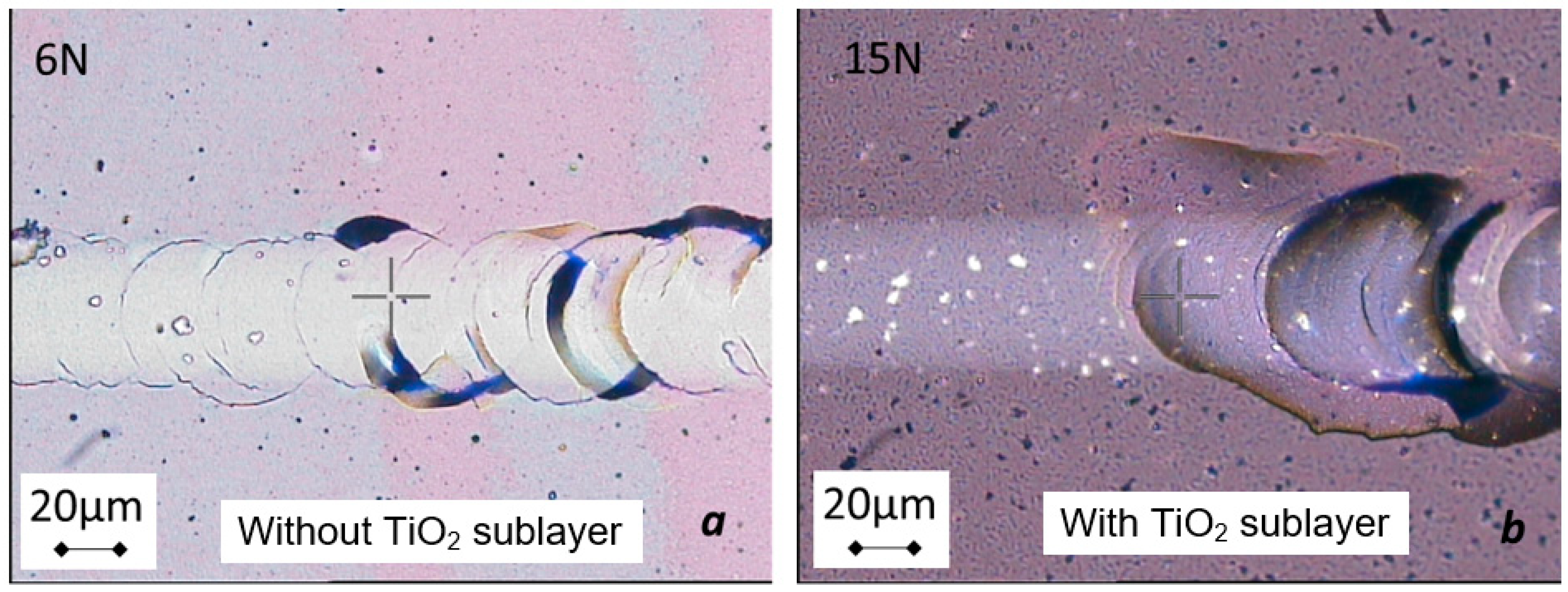
3.1. Adhesion of the Coating at the TiO2@Ag-NPs/Pyrex® Interface

A series of deposits consisting of Ag-NPs dispersed in a TiO2 matrix is produced via DLI-MOCVD on Pyrex® plates. The Ag-NPs and matrix are simultaneously deposited, forming a co-deposit [43]. The TiO2 and Ag precursor vapours (generated via bubbling nitrogen in TTIP and liquid injection, respectively) are concurrently introduced at the substrate level, which is maintained at the deposition reaction temperature. The injection parameters of the Ag precursor are maintained constant for the series, and only the deposition duration is altered to achieve a mass range of 3–15 mg of the deposited TiO2@Ag-NPs. Furthermore, previous results obtained using neat TiO2 have demonstrated that the back-side illumination configuration in a photocatalytic reactor facilitates an optimal mass of the deposited photocatalyst [39].
This first step comprising the screening of the mass for deposition emphasises the issue of the adhesion of the TiO2@Ag-NPs coating at the TiO2@Ag-NPs/Pyrex® interface because the presence of metal nanoparticles that germinate on the substrate surface weakens the interface, as they induce a preferential initiation of adhesive rupture. This issue has been reported for thin Ag layers on non-metallic substrates, such as glass and polymers [46]. The deposition of an adhesion sublayer of neat TiO2 by ensuring good chemical continuity, as illustrated in Figure 1, can address the aforementioned difficulty. The improvement of the adhesion of metal deposits due to the presence of a TiO2 layer has been previously observed [33,47].
Scratch test measurements confirm that the sublayer considerably improves the adhesion of the coating. For a specific deposited mass, the first flaking appears at a critical load of 6 N in the absence of the adhesion sublayer, whereas it occurs at 15 N in the presence of the TiO2 adhesion sublayer (Figure 2).

3.2. Effects of the Adhesion Sublayer on the TiO2@Ag-NPs Coating Morphology

Three doped deposits are formed on Pyrex® substrates and comprise a TiO2 sublayer and a TiO2@Ag-NPs layer (Figure 1b). The as-formed samples are labelled C-Ag-3, C-Ag-7, and C-Ag-15 based on their deposited mass of 2.9, 6.5, and 15 mg, respectively. These coatings are compared with a reference of neat TiO2 and TiO2@Ag-NPs without the adhesion sublayer, which are labelled C-7 (7 mg) and C-Ag-6 (5.9 mg), respectively. The morphology and structure of all these samples are characterised to determine the potential effects on the adhesion sublayer.
Figure 3 presents the XRD patterns of the TiO2@Ag-NPs deposits with (C-Ag-3, C-Ag-7, and C-Ag-15) and without (C-Ag-6) the adhesion sublayer as well as of neat TiO2 (C-7). The patterns reveal a characteristic crystalline structure of anatase TiO2, which is consistent with JCPDS #00-021-1272 [48,49]. Furthermore, the characteristic peaks of the face-centred cubic crystal structure of Ag (JCPDS #04-0783) [50,51] are particularly visible in the C-Ag-6 pattern. Considering that the Ag deposition parameters (concentration of the injectable solution, frequency, and opening time of the injectors) are identical for the entire series of TiO2@Ag-NPs coatings, the absence of the TiO2 sublayer appears to influence the germination/growth of Ag particles, leading to the formation of larger agglomerates, which is clearer in the XRD patterns when the co-deposition is directly performed on the substrate. Considering the texturing, for the C-7 deposit (neat TiO2) and the doped C-Ag-3, C-Ag-6, and C-Ag-7 deposits with respect to the intensities of the peaks of the JCPDS reference, a particularly intense peak (101) at 25.3° is observed, and a texturing corresponding to the (211) plane is prominent at 55.11° for the C-Ag-15 sample.
Furthermore, the structure/morphology relation is confirmed, indicating that texturing is associated with the difference in morphologies (Figure 4). In both cases (with (C-Ag-3, -7, and -15) and without (C-Ag-6) the adhesion sublayer), the structuring is columnar; however, the orientation and size of the columns differ depending on the texturing of the deposit according to the (211) plane in DRX. For the C-Ag-15 coating, which comprises a textured (211) plane, the columns are thinner and are oriented in the same manner, resulting in an arithmetic roughness of 5 nm. Conversely, for the C-7, C-Ag-3, and C-Ag-7 deposits, whose patterns are in accordance with the relative intensities of the JCPDS reference sheet, the columns are wider and have an apparent disorganisation with a more random distribution of growth directions. This morphology presents a roughness of 10–15 nm.
Finally, the presence of the TiO2 sublayer clearly affects the co-deposit growth [33,46]. The TiO2 sublayer appears to ensure a continuity in morphology, as no notable differences are observed in the microstructures of the C-7 and C-Ag-7 deposits in the SEM and XRD analyses. In contrast, the C-Ag-6 deposit presents a considerably different morphology, featuring larger Ag agglomerates. The sublayer plausibly directs the growth mode of the co-deposit by promoting the continuity in the morphology of the TiO2 matrix and the homogeneous incorporation of Ag within the matrix. In the absence of the adhesion sublayer, Ag germinates on the Pyrex® glass substrate, and the growth of these germs appears to be preferred, as Ag is detected both in EDS (Figure 5) and in XRD (Figure 3) analyses, in contrast to the case of the C-Ag-3, C-Ag-7, and C-Ag-15 samples.
The aforementioned morphology observations are correlated with the ability of the samples to transmit visible light, as depicted in Figure 6. The deposit is opaquer, as the coating mass is important. Additionally, the presence of Ag aggregates impede the transparency of the coating (C-Ag-6) [52,53], whereas the effects of Ag particles are negligible when they are dispersed within the TiO2 matrix (C-7 vs. C-Ag-7).

3.3. Photocatalytic Activity Under Visible Irradiation

The kinetics of the photocatalytic degradation of diuron by the neat TiO2 deposit and Ag-doped TiO2 (with and without the sublayer) under visible LED illumination are presented in Figure 7. Adsorption (UV-OFF) and photolysis (without the photocatalyst) result in an elimination of <10% of diuron, which is consistent with the findings of previous studies [39]. The efficiency of the reference TiO2 deposit without doping (C-7) is similar to that of photolysis, confirming its inactivity under visible irradiation. Moreover, the C-Ag-15 deposit does not exhibit any photocatalytic activity because its effect is similar to that of photolysis. This result can be primarily attributed to light attenuation within the coating itself, which leads to the generation of charge carriers at the photocatalyst/support interface; these carriers tend to recombine before they are able to migrate to the photocatalyst/solution interface [54].
The C-Ag-3, C-Ag-6, and C-Ag-7 deposits reduced the initial diuron concentration by 18%, 20%, and 32%, respectively, after 480 min of visible irradiation (λ > 400 nm). These results demonstrate that TiO2@Ag-NPs photocatalysts exhibit activity within the visible spectrum with efficiencies comparable to those reported in certain studies [36,55]. According to the literature, efficiencies ranging from 35% to 98% have been attributed to the activation of TiO2 photocatalysts doped with Ag-NPs (Table 2). However, it is important to note that many of these studies employed illumination systems with wavelengths in the UV range, which can degrade the target molecule by direct photolysis and also activate the TiO2 photocatalyst itself, independently of the Ag-NPs doping. Therefore, the improvements introduced by Ag-NPs doping are estimated to range between 10% and 60% (Table 2). Figure 8 reveals a slight decrease in the TOC content in the case of C-Ag-7, which is consistent with the limited reduction rates observed. These findings lead to the following conclusions:
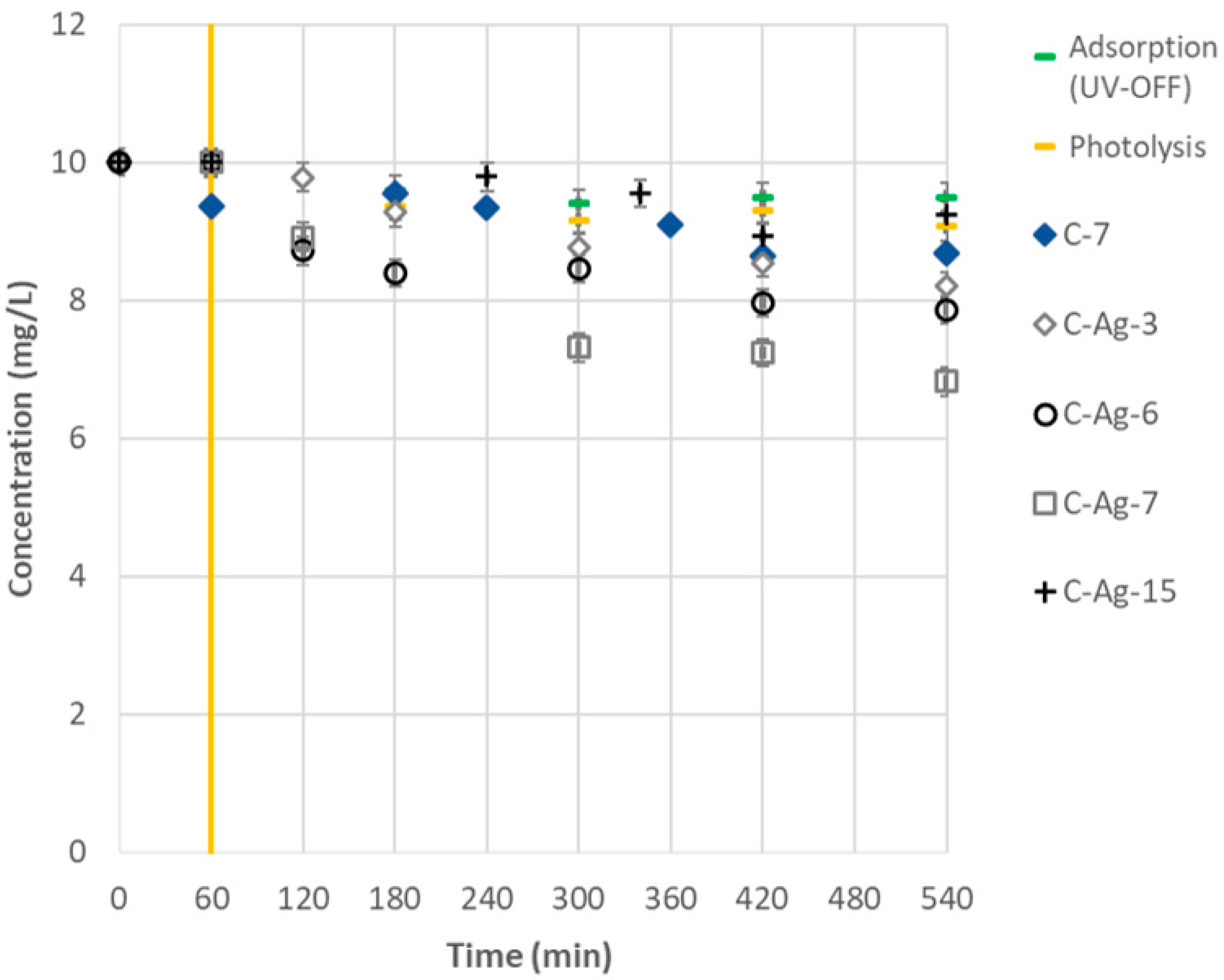
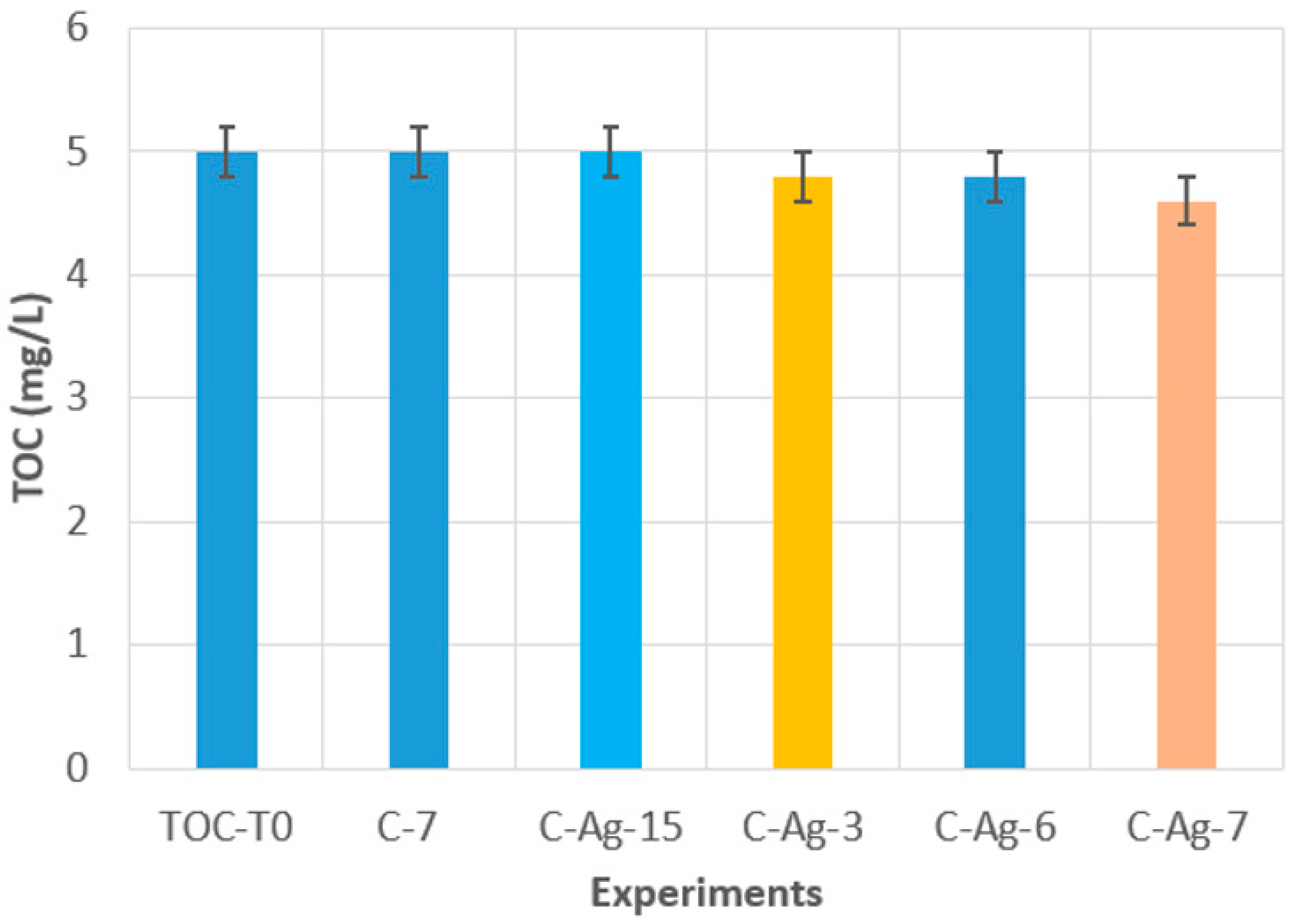
  • The ability of Ag doping to trigger photocatalytic activity is confirmed because neat TiO2 is inactive, whereas doped TiO2 contributes to decreasing the initial amount of diuron (C-7 and C-Ag-7).
  • The coating thickness is important, particularly in the back-side illumination mode (C-Ag-3, C-Ag-7, and C-Ag-15). The existence of an optimal photocatalyst thickness is confirmed; below and above this optimum thickness, the photocatalytic activity decreases as demonstrated in Ref. [39].
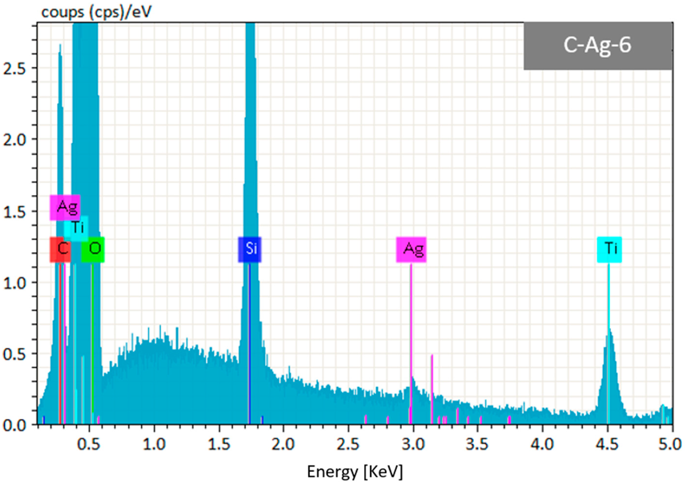
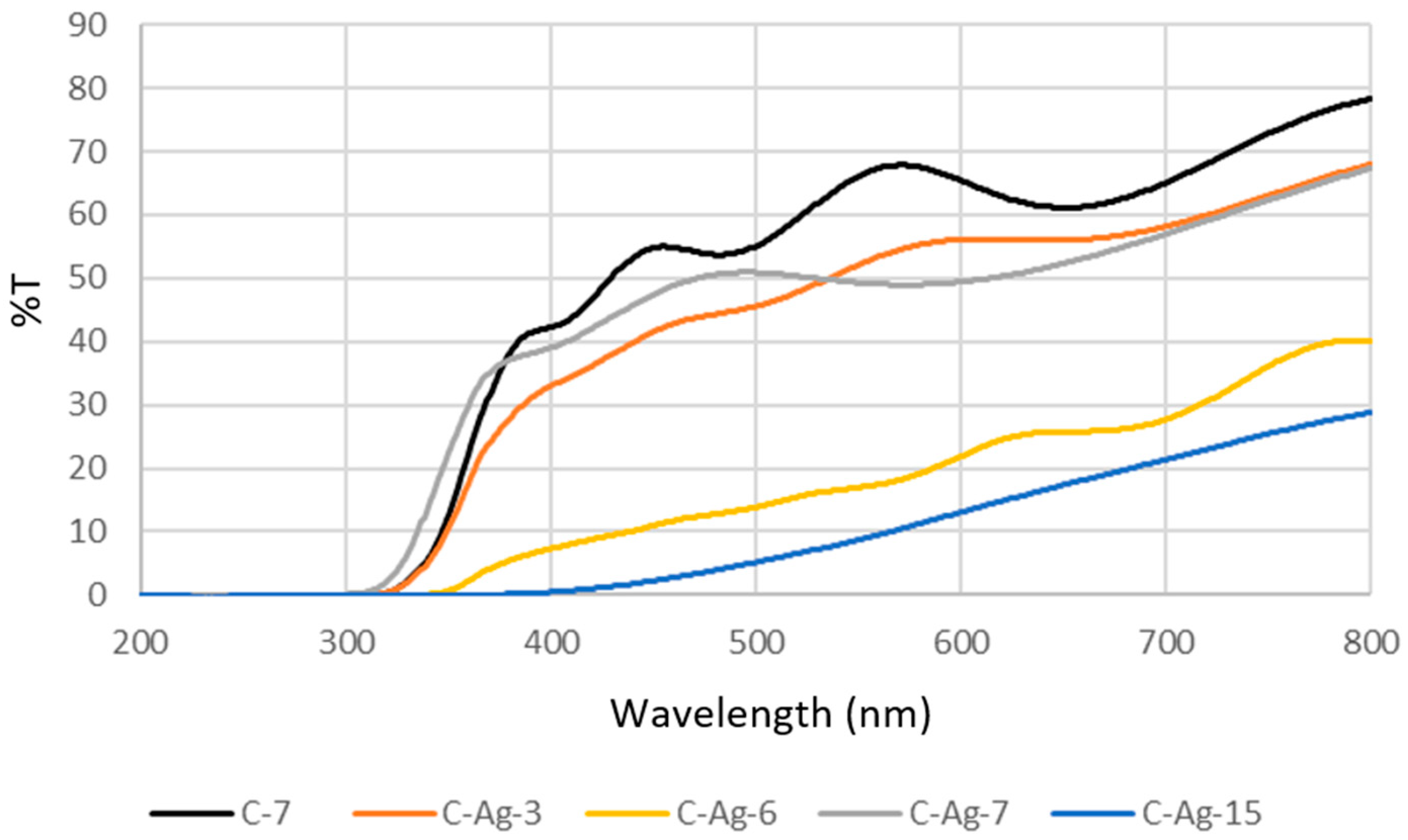
  • The dispersion and the growth mode of Ag particles considerably affect the attenuation of the incident radiation, particularly in the back-side illumination mode (C-Ag-6 and C-Ag-7). The presence of the TiO2 adhesion sublayer promotes the dispersion of Ag-NPs within the matrix and limits the formation of large aggregates, ensuring the lowest radiation attenuation and enabling the photocatalytic activity in the visible range.
The diuron removal efficiencies are low; however, the LED irradiation is completely in the visible spectrum, comprising wavelengths of >400 nm and a maximum peak at approximately 500 nm. This ensures the effective activation of the catalyst in the visible spectral region without interference from the UV spectrum.

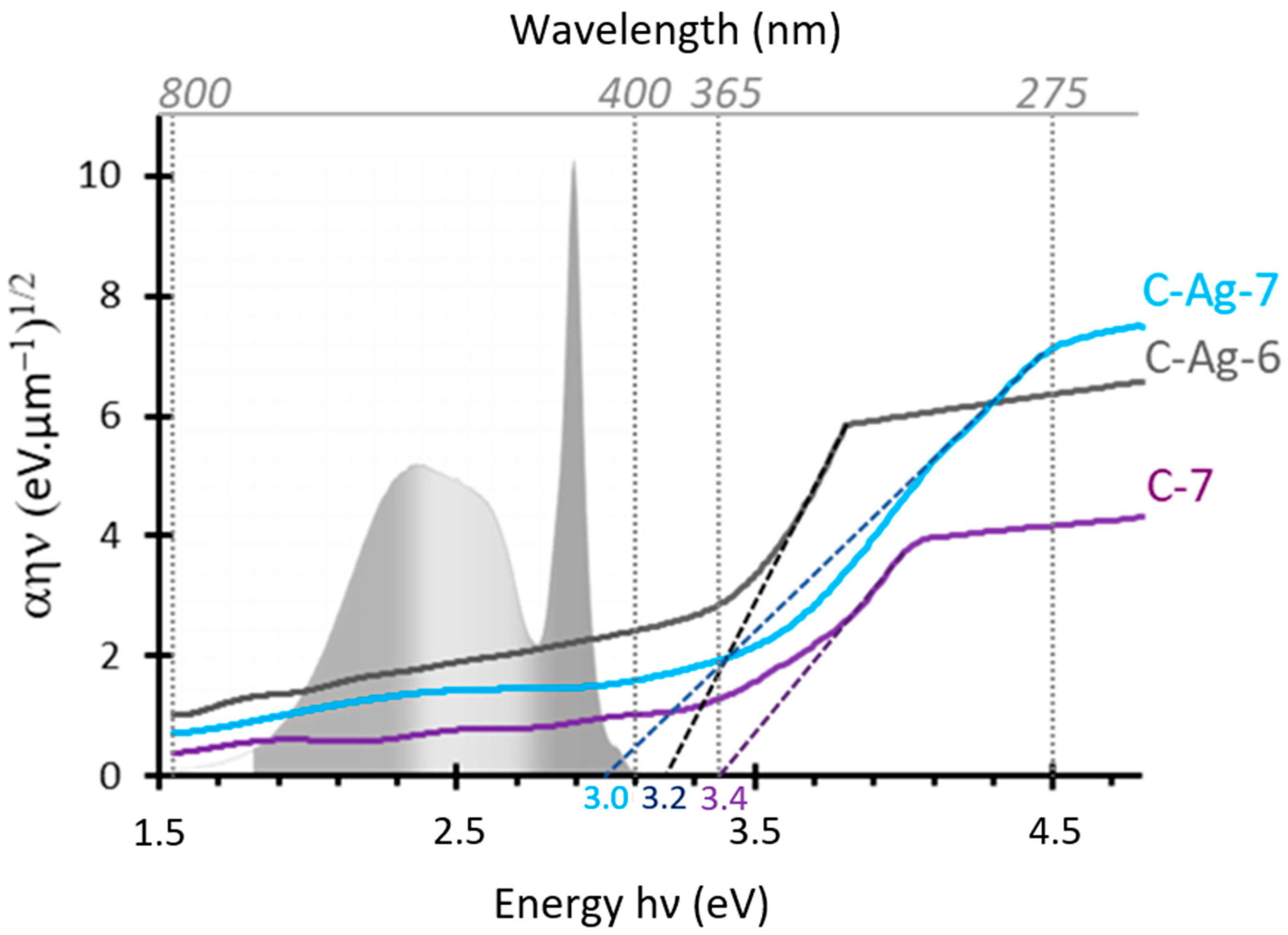
3.4. Effects of Doping on the Bandgap of Photocatalysts

The activation of different photocatalysts by visible irradiation is consistent with the bandgaps calculated using the Tauc representation [44], as illustrated in Figure 9. The addition of Ag-NPs into the TiO2 matrix effectively shifts the bandgap towards low energies, from 3.4 eV for neat TiO2 to 3.2 and 3 eV for TiO2@Ag-NPs without and with the adhesion sublayer, respectively. However, only the photocatalysts possessing a bandgap of <3.1 eV (corresponding to a wavelength of 400 nm) are likely to be activated. This explains the activity of the C-Ag-7 sample; when it is effectively activated by the visible LED panel, it only uses a substantially small number of the emitted photons, limiting the reduction in the diuron concentration in the solution.

4. Conclusions

The doping of a TiO2 deposit with Ag-NPs shifts the photocatalytic activity of TiO2 into the visible range, and the application of the resulting material decreases the diuron content in water. Although the yield of diuron degradation is limited because the reduction peaks at 32%, this study emphasises the effects of the nanoparticle growth mode on the photocatalytic activity. Furthermore, the presence of a TiO2 sublayer ensures the adhesion of the coating, promotes the dispersion of the nanoparticles within the matrix, ensures good chemical continuity, and limits the growth of large Ag agglomerates. This limits the attenuation of the incident radiation (and therefore the reduction in the photon flux) and decreases the bandgap energy by creating a heterojunction, achieving photocatalytic activity in the visible range.

5. Recommendations

The findings of this study are promising and provide a proof of concept that should be optimised through future research to improve the abatement kinetics. The following avenues can be explored in future:
  • Increasing the incident photon flux by concentrating the solar radiation;
  • The determination of the illumination mode (front-side illumination vs. back-side illumination) that can overcome the attenuation of the incident radiation;
  • The optimisation of the coating architecture by investigating the effects of different Ag particle contents or a multilayer organisation;
  • Costs, life cycle, and long-term stability should be studied in depth for a possible change of scale.

Author Contributions

C.A., C.T., C.Y.Q.-C. and T.T. designed and supervised the experiments. C.Y.Q.-C. performed the experiments, TOC, and HPLC–UV analysis. C.T. performed the TiO2@Ag-NPs compact coating on Pyrex and its characterisations by XRD, SEM, EDX, and UV–Vis. C.Y.Q.-C., C.T., T.T., A.I.V.-A., M.M.S.-C. and C.A. wrote the paper. All authors have read and agreed to the published version of the manuscript.

Funding

This research received no external funding.

Data Availability Statement

The data presented in this study are available on request from the corresponding author.

Acknowledgments

The authors are grateful for the support of the projects ANR TRANSPRO and POA-INV-2799. The first was financed by Agence National de la Recherche (ANR) within the Laboratoire de Génie Chimique (Université de Toulouse, CNRS, INPT, UPS), EPOC (Université de Bordeaux, CNRS, Bordeaux INP, EPHE), and REVERSAAL (INRAE). The second was financed by the Universidad Cooperativa de Colombia—UCC within the ISI Research Group.

Conflicts of Interest

The authors declare no conflicts of interest.

Abbreviations

The following abbreviations are used in this manuscript:
Ag-NPsSilver nanoparticles
LEDsLight-emitting diodes
UVUltraviolet
MOCVDMetal–organic chemical vapour deposition
CVDChemical vapour deposition
DLIDirect liquid injection
XRDX-ray diffraction
SEMScanning electron microscopy
EDSEnergy-dispersive spectroscopy
HPLCHigh-performance liquid chromatography
TOCTotal organic carbon
JCPDSJoint Committee on Powder Diffraction Standards

References

  1. UNESCO. The United Nations World Water Development Report 2023: Partnerships and Cooperation for Water; UNESCO Biblioteca Digital: Paris, France, 2023; Available online: https://unesdoc.unesco.org/ark:/48223/pf0000384655 (accessed on 2 October 2023).
  2. Alexa, E.T.; Bernal-Romero del Hombre Bueno, M.d.l.Á.; González, R.; Sánchez, A.V.; García, H.; Prats, D. Occurrence and Removal of Priority Substances and Contaminants of Emerging Concern at the WWTP of Benidorm (Spain). Water 2022, 14, 4129. [Google Scholar] [CrossRef]
  3. Paijens, C.; Frère, B.; Caupos, E.; Moilleron, R.; Bressy, A. Determination of 18 Biocides in Both the Dissolved and Particulate Fractions of Urban and Surface Waters by HPLC-MS/MS. Water. Air. Soil Pollut. 2020, 231, 210. [Google Scholar] [CrossRef]
  4. Luo, Y.; Guo, W.; Ngo, H.H.; Nghiem, L.D.; Hai, F.I.; Zhang, J.; Liang, S.; Wang, X.C. A Review on the Occurrence of Micropollutants in the Aquatic Environment and Their Fate and Removal during Wastewater Treatment. Sci. Total Environ. 2014, 473–474, 619–641. [Google Scholar] [CrossRef] [PubMed]
  5. Wu, K.; Atasoy, M.; Zweers, H.; Rijnaarts, H.; Langenhoff, A.; Fernandes, T.V. Impact of Wastewater Characteristics on the Removal of Organic Micropollutants by Chlorella Sorokiniana. J. Hazard. Mater. 2023, 453, 131451. [Google Scholar] [CrossRef]
  6. Quintero-Castañeda, C.Y.; Acevedo, P.A.; Hernández-Angulo, L.R.; Tobón-Vélez, D.; Franco-Leyva, A.; Sierra-Carrillo, M.M. Wastewater Treatment by Coupling Adsorption and Photocatalytic Oxidation: A Review of the Removal of Phenolic Compounds in the Oil Industry. Eng 2024, 5, 2441–2461. [Google Scholar] [CrossRef]
  7. Triquet, T.; Tendero, C.; Latapie, L.; Manero, M.-H.; Richard, R.; Andriantsiferana, C. TiO2 MOCVD Coating for Photocatalytic Degradation of Ciprofloxacin Using 365 Nm UV LEDs - Kinetics and Mechanisms. J. Environ. Chem. Eng. 2020, 8, 104544. [Google Scholar] [CrossRef]
  8. Andriantsiferana, C.; Mohamed, E.F.; Delmas, H. Photocatalytic Degradation of an Azo-Dye on TiO2/Activated Carbon Composite Material. Environ. Technol. 2014, 35, 355–363. [Google Scholar] [CrossRef]
  9. Sathishkumar, P.; Mangalaraja, R.V.; Anandan, S. Review on the Recent Improvements in Sonochemical and Combined Sonochemical Oxidation Processes—A Powerful Tool for Destruction of Environmental Contaminants. Renew. Sustain. Energy Rev. 2016, 55, 426–454. [Google Scholar] [CrossRef]
  10. Weng, B.; Qi, M.-Y.; Han, C.; Tang, Z.-R.; Xu, Y.-J. Photocorrosion Inhibition of Semiconductor-Based Photocatalysts: Basic Principle, Current Development, and Future Perspective. ACS Catal. 2019, 9, 4642–4687. [Google Scholar] [CrossRef]
  11. Anaya-Rodríguez, F.; Durán-Álvarez, J.C.; Drisya, K.T.; Zanella, R. The Challenges of Integrating the Principles of Green Chemistry and Green Engineering to Heterogeneous Photocatalysis to Treat Water and Produce Green H2. Catalysts 2023, 13, 154. [Google Scholar] [CrossRef]
  12. Abd Rahman, N.; Choong, C.E.; Pichiah, S.; Nah, I.W.; Kim, J.R.; Oh, S.-E.; Yoon, Y.; Choi, E.H.; Jang, M. Recent Advances in the TiO2 Based Photoreactors for Removing Contaminants of Emerging Concern in Water. Sep. Purif. Technol. 2023, 304, 122294. [Google Scholar] [CrossRef]
  13. Gopalan, A.-I.; Lee, J.-C.; Saianand, G.; Lee, K.-P.; Sonar, P.; Dharmarajan, R.; Hou, Y.; Ann, K.-Y.; Kannan, V.; Kim, W.-J. Recent Progress in the Abatement of Hazardous Pollutants Using Photocatalytic TiO2-Based Building Materials. Nanomaterials 2020, 10, 1854. [Google Scholar] [CrossRef]
  14. Ahmadpour, N.; Nowrouzi, M.; Madadi Avargani, V.; Sayadi, M.H.; Zendehboudi, S. Design and Optimization of TiO2-Based Photocatalysts for Efficient Removal of Pharmaceutical Pollutants in Water: Recent Developments and Challenges. J. Water Process Eng. 2024, 57, 104597. [Google Scholar] [CrossRef]
  15. Wetchakun, K.; Wetchakun, N.; Sakulsermsuk, S. An Overview of Solar/Visible Light-Driven Heterogeneous Photocatalysis for Water Purification: TiO2- and ZnO-Based Photocatalysts Used in Suspension Photoreactors. J. Ind. Eng. Chem. 2019, 71, 19–49. [Google Scholar] [CrossRef]
  16. Malato, S.; Blanco, J.; Vidal, A.; Richter, C. Photocatalysis with Solar Energy at a Pilot-Plant Scale: An Overview. Appl. Catal. B Environ. 2002, 37, 1–15. [Google Scholar] [CrossRef]
  17. Minero, C.; Pelizzetti, E.; Malato, S.; Blanco, J. Large Solar Plant Photocatalytic Water Decontamination: Degradation of Pentachlorophenol. Chemosphere 1993, 26, 2103–2119. [Google Scholar] [CrossRef]
  18. Rengifo-Herrera, J.A.; Pulgarin, C. Why Five Decades of Massive Research on Heterogeneous Photocatalysis, Especially on TiO2, Has Not yet Driven to Water Disinfection and Detoxification Applications? Critical Review of Drawbacks and Challenges. Chem. Eng. J. 2023, 477, 146875. [Google Scholar] [CrossRef]
  19. Fkiri, A.; Saidani, M.A.; Chmangui, A.; Smiri, L.S. One-Pot Synthesis of Copper-Doped ZnO Nanorods Photocatalysts: Degradation of Diuron Herbicide Under Simulated Solar Light. J. Inorg. Organomet. Polym. Mater. 2023, 33, 2523–2530. [Google Scholar] [CrossRef]
  20. Li, N.; Gao, X.; Su, J.; Gao, Y.; Ge, L. Metallic WO2-Decorated g-C3N4 Nanosheets as Noble-Metal-Free Photocatalysts for Efficient Photocatalysis. Chin. J. Catal. 2023, 47, 161–170. [Google Scholar] [CrossRef]
  21. Singh, A.; Singh, J.; Vasishth, A.; Kumar, A.; Pattnaik, S.S. Emerging Materials in Advanced Oxidation Processes for Micropollutant Treatment Process. In Advanced Oxidation Processes for Micropollutant Remediation; CRC Press: Boca Raton, FL, USA, 2023; pp. 133–155. ISBN 978-1-00-090654-7. [Google Scholar]
  22. Bensouici, F.; Souier, T.; Dakhel, A.A.; Iratni, A.; Tala-Ighil, R.; Bououdina, M. Synthesis, Characterization and Photocatalytic Behavior of Ag Doped TiO2 Thin Film. Superlattices Microstruct. 2015, 85, 255–265. [Google Scholar] [CrossRef]
  23. Çifçi, D.İ. Decolarization of Methylene Blue and Methyl Orange with Ag Doped TiO2 under UV-A and UV-Visible Conditions: Process Optimization by Response Surface Method and Toxicity Evaluation. Glob. NEST J. 2016, 18, 371–380. [Google Scholar] [CrossRef]
  24. de la Cruz, D.; Arévalo, J.C.; Torres, G.; Margulis, R.G.B.; Ornelas, C.; Aguilar-Elguézabal, A. TiO2 Doped with Sm3+ by Sol–Gel: Synthesis, Characterization and Photocatalytic Activity of Diuron under Solar Light. Catal. Today 2011, 166, 152–158. [Google Scholar] [CrossRef]
  25. Horovitz, I.; Avisar, D.; Baker, M.A.; Grilli, R.; Lozzi, L.; Di Camillo, D.; Mamane, H. Carbamazepine Degradation Using a N-Doped TiO2 Coated Photocatalytic Membrane Reactor: Influence of Physical Parameters. J. Hazard. Mater. 2016, 310, 98–107. [Google Scholar] [CrossRef] [PubMed]
  26. Luna-Sanguino, G.; Tolosana-Moranchel, A.; Duran-Valle, C.; Faraldos, M.; Bahamonde, A. Optimizing P25-RGO Composites for Pesticides Degradation: Elucidation of Photo-Mechanism. Catal. Today 2019, 328, 172–177. [Google Scholar] [CrossRef]
  27. Wang, Q.; Tang, Z.; Herout, R.; Liu, C.; Yu, K.; Lange, D.; Godin, R.; Kizhakkedathu, J.N.; Troczynski, T.; Wang, R. Axial Suspension Plasma Sprayed Ag-TiO2 Coating for Enhanced Photocatalytic and Antimicrobial Properties. Surf. Interfaces 2024, 45, 103856. [Google Scholar] [CrossRef]
  28. Borrego Pérez, J.A.; Morales, E.R.; Paraguay Delgado, F.; Meza Avendaño, C.A.; Alonso Guzman, E.M.; Mathews, N.R. Ag Nanoparticle Dispersed TiO2 Thin Films by Single Step Sol Gel Process: Evaluation of the Physical Properties and Photocatalytic Degradation. Vacuum 2023, 215, 112276. [Google Scholar] [CrossRef]
  29. Pawar, R.C.; Lee, C.S. Chapter 1-Basics of Photocatalysis. In Heterogeneous Nanocomposite-Photocatalysis for Water Purification; Pawar, R.C., Lee, C.S., Eds.; William Andrew Publishing: Boston, MA, USA, 2015; pp. 1–23. ISBN 978-0-323-39310-2. [Google Scholar]
  30. Huang, B.-S.; Chang, F.-Y.; Wey, M.-Y. Photocatalytic Properties of Redox-Treated Pt/TiO2 Photocatalysts for H2 Production from an Aqueous Methanol Solution. Int. J. Hydrogen Energy 2010, 35, 7699–7705. [Google Scholar] [CrossRef]
  31. Katsumata, H.; Sada, M.; Nakaoka, Y.; Kaneco, S.; Suzuki, T.; Ohta, K. Photocatalytic Degradation of Diuron in Aqueous Solution by Platinized TiO2. J. Hazard. Mater. 2009, 171, 1081–1087. [Google Scholar] [CrossRef] [PubMed]
  32. Khan, M.M.; Ansari, S.A.; Lee, J.; Cho, M.H. Enhanced Optical, Visible Light Catalytic and Electrochemical Properties of Au@TiO2 Nanocomposites. J. Ind. Eng. Chem. 2013, 19, 1845–1850. [Google Scholar] [CrossRef]
  33. Schaefer, B.T.; Cheung, J.; Ihlefeld, J.F.; Jones, J.L.; Nagarajan, V. Stability and Dewetting Kinetics of Thin Gold Films on Ti, TiOx and ZnO Adhesion Layers. Acta Mater. 2013, 61, 7841–7848. [Google Scholar] [CrossRef]
  34. Shi, Y.; Ma, J.; Chen, Y.; Qian, Y.; Xu, B.; Chu, W.; An, D. Recent Progress of Silver-Containing Photocatalysts for Water Disinfection under Visible Light Irradiation: A Review. Sci. Total Environ. 2022, 804, 150024. [Google Scholar] [CrossRef] [PubMed]
  35. Demirci, S.; Dikici, T.; Yurddaskal, M.; Gultekin, S.; Toparli, M.; Celik, E. Synthesis and Characterization of Ag Doped TiO2 Heterojunction Films and Their Photocatalytic Performances. Appl. Surf. Sci. 2016, 390, 591–601. [Google Scholar] [CrossRef]
  36. Guillén-Santiago, A.; Mayén, S.A.; Torres-Delgado, G.; Castanedo-Pérez, R.; Maldonado, A.; de la, L. Olvera, M. Photocatalytic Degradation of Methylene Blue Using Undoped and Ag-Doped TiO2 Thin Films Deposited by a Sol–Gel Process: Effect of the Ageing Time of the Starting Solution and the Film Thickness. Mater. Sci. Eng. B 2010, 174, 84–87. [Google Scholar] [CrossRef]
  37. Yu, J.; Xiong, J.; Cheng, B.; Liu, S. Fabrication and Characterization of Ag–TiO2 Multiphase Nanocomposite Thin Films with Enhanced Photocatalytic Activity. Appl. Catal. B Environ. 2005, 60, 211–221. [Google Scholar] [CrossRef]
  38. Panis, C.; Candiotto, L.Z.P.; Gaboardi, S.C.; Gurzenda, S.; Cruz, J.; Castro, M.; Lemos, B. Widespread Pesticide Contamination of Drinking Water and Impact on Cancer Risk in Brazil. Environ. Int. 2022, 165, 107321. [Google Scholar] [CrossRef]
  39. Quintero-Castañeda, C.Y.; Tendero, C.; Triquet, T.; Acevedo, P.A.; Latapie, L.; Sierra-Carrillo, M.M.; Andriantsiferana, C. Towards a Better Understanding of the Back-Side Illumination Mode on Photocatalytic Metal–Organic Chemical Vapour Deposition Coatings Used for Treating Wastewater Polluted by Pesticides. Water 2024, 16, 1. [Google Scholar] [CrossRef]
  40. Chin-Pampillo, J.S.; Perez-Villanueva, M.; Masis-Mora, M.; Mora-Dittel, T.; Carazo-Rojas, E.; Alcañiz, J.M.; Chinchilla-Soto, C.; Domene, X. Amendments with Pyrolyzed Agrowastes Change Bromacil and Diuron’s Sorption and Persistence in a Tropical Soil without Modifying Their Environmental Risk. Sci. Total Environ. 2021, 772, 145515. [Google Scholar] [CrossRef] [PubMed]
  41. Silva, T.S.; Araújo de Medeiros, R.C.; Silva, D.V.; de Freitas Souza, M.; das Chagas, P.S.F.; Lins, H.A.; da Silva, C.C.; Souza, C.M.M.; Mendonça, V. Interaction between Herbicides Applied in Mixtures Alters the Conception of Its Environmental Impact. Environ. Sci. Pollut. Res. 2022, 29, 15127–15143. [Google Scholar] [CrossRef]
  42. Mercurio, P.; Mueller, J.F.; Eaglesham, G.; O’Brien, J.; Flores, F.; Negri, A.P. Degradation of Herbicides in the Tropical Marine Environment: Influence of Light and Sediment. PLoS ONE 2016, 11, e0165890. [Google Scholar] [CrossRef]
  43. Sarantopoulos, C. Photocatalyseurs à Base de TiO2 Préparés Par Infiltration Chimique En Phase Vapeur (CVI) Sur Supports Microfibreux. Ph.D. Thesis, INPT, Toulouse, France, 2007. [Google Scholar]
  44. Miquelot, A.; Youssef, L.; Villeneuve-Faure, C.; Prud’homme, N.; Dragoe, N.; Nada, A.; Rouessac, V.; Roualdes, S.; Bassil, J.; Zakhour, M.; et al. In- and out-Plane Transport Properties of Chemical Vapor Deposited TiO2 Anatase Films. J. Mater. Sci. 2021, 56, 10458–10476. [Google Scholar] [CrossRef]
  45. Shetty, A.; Goyal, A. Total Organic Carbon Analysis in Water—A Review of Current Methods. Mater. Today Proc. 2022, 65, 3881–3886. [Google Scholar] [CrossRef]
  46. Jeong, E.; Zhao, G.; Lee, S.-G.; Bae, J.-S.; Yu, S.M.; Mun, C.; Han, S.Z.; Lee, G.-H.; Ikoma, Y.; Choi, E.-A.; et al. Exploring SiOx as an Effective Adhesion Promoter for Ag on Glass and Polymer Substrates. Appl. Surf. Sci. 2025, 688, 162342. [Google Scholar] [CrossRef]
  47. Abe, N.; Otani, Y.; Miyake, M.; Kurita, M.; Takeda, H.; Okamura, S.; Shiosaki, T. Influence of a TiO2 Adhesion Layer on the Structure and the Orientation of a Pt Layer in Pt/TiO2/SiO2/Si Structures. Jpn. J. Appl. Phys. 2003, 42, 2791. [Google Scholar] [CrossRef]
  48. Al-Mamun, M.R.; Kader, S.; Islam, M.S.; Khan, M.Z.H. Photocatalytic Activity Improvement and Application of UV-TiO2 Photocatalysis in Textile Wastewater Treatment: A Review. J. Environ. Chem. Eng. 2019, 7, 103248. [Google Scholar] [CrossRef]
  49. Galenda, A.; Natile, M.M.; El Habra, N. Large-Scale MOCVD Deposition of Nanostructured TiO2 on Stainless Steel Woven: A Systematic Investigation of Photoactivity as a Function of Film Thickness. Nanomaterials 2022, 12, 992. [Google Scholar] [CrossRef]
  50. Sarkar, S.; Das, R. Shape Effect on the Elastic Properties of Ag Nanocrystals. Micro Nano Lett. 2018, 13, 312–315. [Google Scholar] [CrossRef]
  51. Ali, M.H.; Azad, M.A.K.; Khan, K.A.; Rahman, M.O.; Chakma, U.; Kumer, A. Analysis of Crystallographic Structures and Properties of Silver Nanoparticles Synthesized Using PKL Extract and Nanoscale Characterization Techniques. ACS Omega 2023, 8, 28133–28142. [Google Scholar] [CrossRef]
  52. Ling, L.; Feng, Y.; Li, H.; Chen, Y.; Wen, J.; Zhu, J.; Bian, Z. Microwave Induced Surface Enhanced Pollutant Adsorption and Photocatalytic Degradation on Ag/TiO2. Appl. Surf. Sci. 2019, 483, 772–778. [Google Scholar] [CrossRef]
  53. Guitoume, D.; Achour, S.; Sobti, N.; Boudissa, M.; Souami, N.; Messaoudi, Y. Structural, Optical and Photoelectrochemical Properties of TiO2 Films Decorated with Plasmonic Silver Nanoparticles. Optik 2018, 154, 182–191. [Google Scholar] [CrossRef]
  54. Castañeda, C.Y.Q. Photocatalyse Supportée à Base de TiO2: Vers une Meilleure Compréhension de la Dégradation du Diuron en Milieu Aqueux. Ph.D. Thesis, Université de Toulouse, Toulouse, France, 2024. [Google Scholar]
  55. Kusdianto, K.; Jiang, D.; Kubo, M.; Shimada, M. Fabrication of TiO2-Ag Nanocomposite Thin Films via One-Step Gas-Phase Deposition. Ceram. Int. 2017, 43, 5351–5355. [Google Scholar] [CrossRef]
Figure 1. Schematic of the substrate/coating interface without (a) and with (b) the adhesion sublayer.
Water 17 01632 g001
Figure 2. Scratch test stripe: the first adhesive fracture scales appear at 6 (a) and 15 N (b).
Water 17 01632 g002
Figure 3. Diffractograms of the neat TiO2 coating (C-7) and TiO2@Ag-NPs with (C-Ag-3, -7, and -15) and without (C-Ag-6) the adhesion sublayer.
Water 17 01632 g003
Figure 4. SEM images illustrating the top view of neat TiO2 (C-7) and TiO2@Ag-NPs coatings with (C-Ag-3, -7, and -15) and without (C-Ag-6) the sublayer. Surface roughness plot obtained via mechanical profilometry.
Water 17 01632 g004
Figure 5. EDS analysis of the C-Ag-6 sample confirms the presence of Ag-NPs within the coating.
Water 17 01632 g005
Figure 6. UV–visible transmission spectra of the neat TiO2 coating (C-7) and TiO2@Ag-NPs with (C-Ag-3, -7, and -15) and without (C-Ag-6) the adhesion sublayer.
Water 17 01632 g006
Figure 7. Kinetics of diuron degradation by the neat TiO2 coating (C-7) and TiO2@Ag-NPs with (C-Ag-3, -7, and -15) and without (C-Ag-6) the adhesion sublayer under visible irradiation.
Water 17 01632 g007
Figure 8. TOC content after 480 min of diuron degradation using different TiO2@Ag-NPs-doped deposits under visible LED irradiation.
Water 17 01632 g008
Figure 9. Tauc representation used for estimating the bandgap superimposed on the emission spectrum of the visible LED panel.
Water 17 01632 g009
Table 1. Operating conditions of MOCVD deposits and the deposited mass of TiO2@Ag-NPs.
Operating ConditionsCoatings
C-7C-Ag-3C-Ag-6C-Ag-7C-Ag-15
Deposition time (min)
* (TiO2)
** (TiO2@Ag-NPs)
* (2 × 80)* (2 × 10)
+
** (2 × 35)
** (2 × 80)* (2 × 10)
+
** (2 × 60)
* (2 × 10)
+
** (2 × 90)
Temperature of the thermostatic bath of the TTIP bubbler (°C)37
Deposition temperature (°C)475
Deposition pressure (Torr)5
Carrier gas (N2) flow rate (cm3·min−1)8
Dilution gas (N2) flow rate (cm3·min−1)320 (Kemstream injector dilution line) + 210 (classic TiO2 dilution line) = 530
Injector frequency (Hz)-1.5
Injector opening time (ms)-1
Composition of the injectable solution-0.012 M of silver pivalate in a mesitylene/dipropylamine mixture 90/10 vol.
Deposited mass (mg)7.7 ± 0.22.9 ± 0.25.9 ± 0.26.5 ± 0.215.3 ± 0.2
Note: The deposition time was divided into two (2) equal stages to create a coating of constant thickness, changing the orientation of the Pyrex® plate inside the MOCVD reactor. Deposition time only with (*) TiO2 and (**) Ag-NPs dispersed in a TiO2 matrix (co-deposit).
Table 2. Comparison of the effective enhancement by Ag-NPs in the TiO2 photocatalyst.
Deposit MethodTarget
Molecule
Irradiation SourceEfficiency (%) Undoped TiO2Efficiency (%) TiO2@Ag-NPsEffective (%)
Enhancement
Reference
Sol-GelMethylene blueUV + visible lamp365418[35]
Sol-GelRhodamine BUVC lamp508030[22]
Sol-GelMethylene blueUV lamp253510[36]
Sol-GelMethylene blue 389860[28]
LPDmethyl orangeUV lamp 63[37]
PECVDMethylene blueUV lamp609535[55]
MOCVDDiuronVisible LED03232This study
Disclaimer/Publisher’s Note: The statements, opinions and data contained in all publications are solely those of the individual author(s) and contributor(s) and not of MDPI and/or the editor(s). MDPI and/or the editor(s) disclaim responsibility for any injury to people or property resulting from any ideas, methods, instructions or products referred to in the content.

