


Model Test and Numerical Analysis of Landslides in Layered Ion-Type Rare Earth Ore Under Rainfall and Mineral Leaching Conditions


Abstract
1. Introduction
2. Model Test
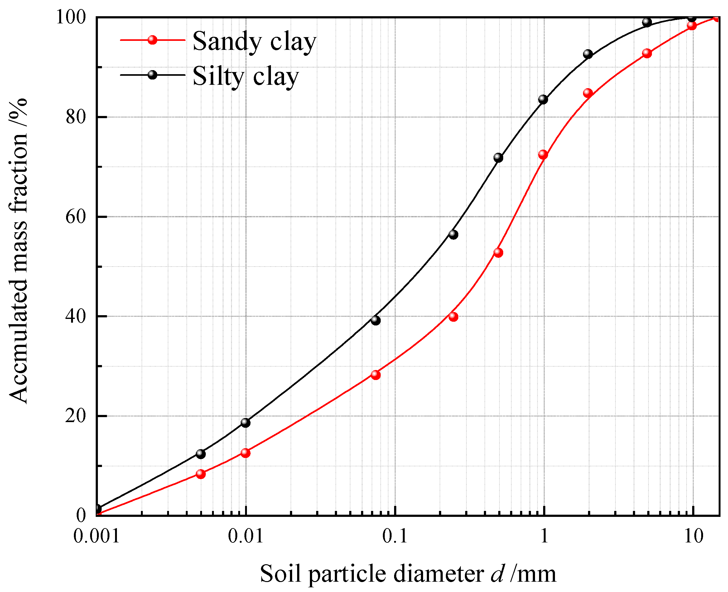
2.1. Experimental Materials
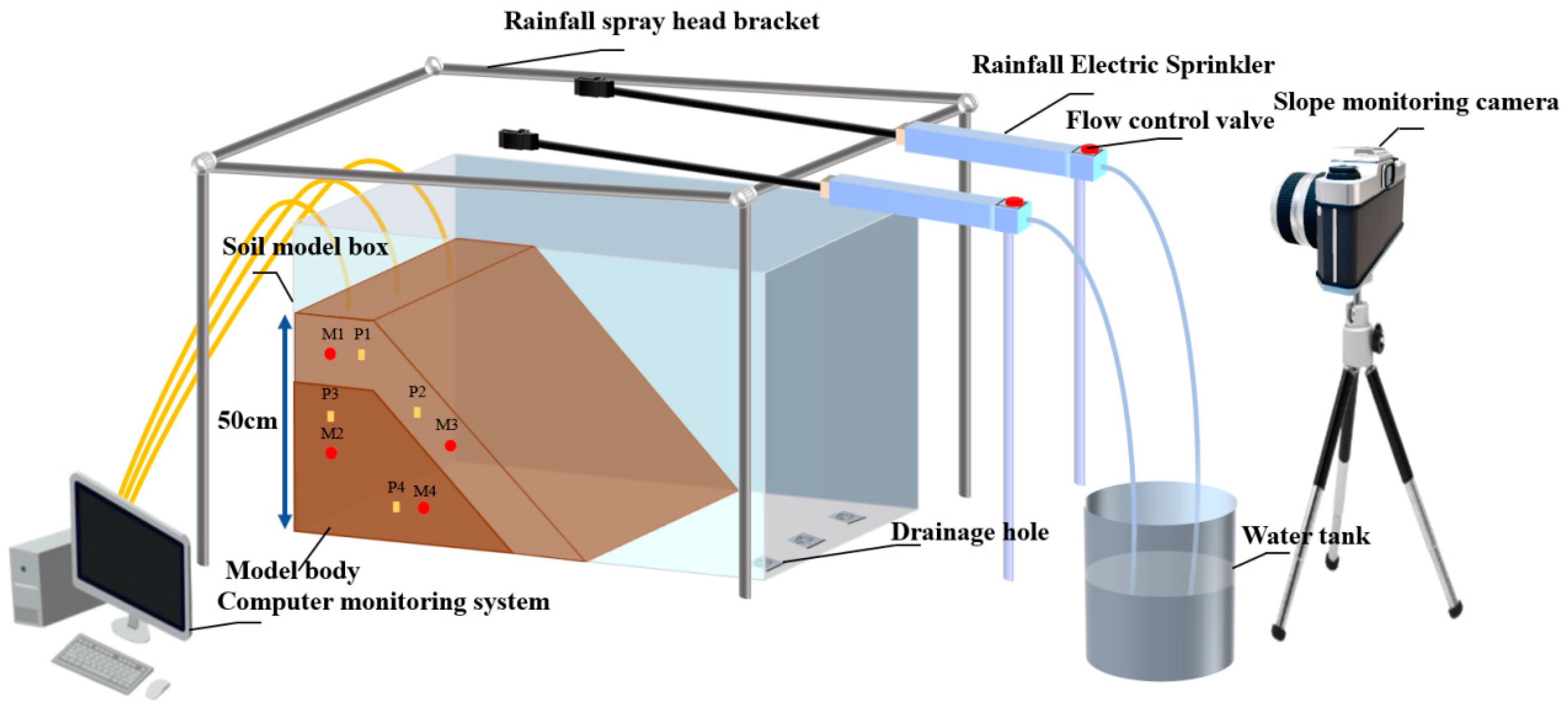
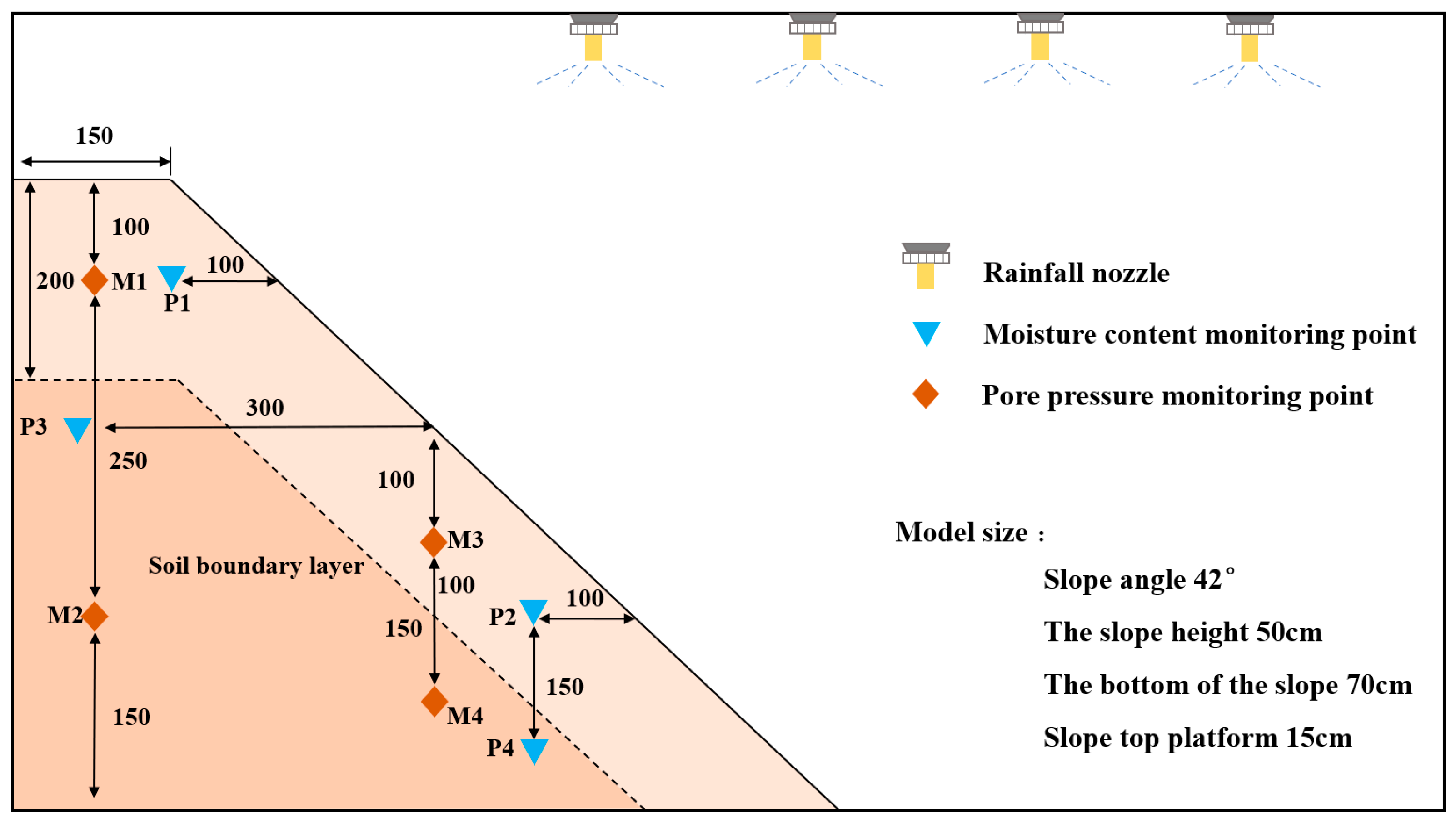
2.2. Experimental Apparatus
2.3. Design of Experimental Conditions for Indoor Simulation Tests
- (1)
- Under different rainfall intensities, the geometric dimensions and initial soil moisture content are kept constant. The study focuses on a layered slope with an upper sandy clay layer and a lower silty clay layer, based on the rainfall intensity historical data from the Gan Nan region and references [29,30]. Three rainfall intensities are set: 30 mm/h for heavy rain, 60 mm/h for torrential rain, and 90 mm/h for extremely heavy rain. The impact of rainfall intensity on slope failure modes and infiltration patterns is explored.
- (2)
- Under different initial moisture contents, a medium rainfall intensity of 30 mm/h is set with a sandy–silty clay layered slope. The initial moisture content of two types of remolded soils is controlled in groups of 15% and 20%, 20% and 25%, and 25% and 30%. The slope failure modes and rainfall infiltration patterns are studied during the experiment.
- (3)
- Under different soil layering sequences, with the same geometric dimensions of the slope model and a slope angle of 42°, the moisture content of completely dried silty clay and sandy clay is remolded. The moisture content of the two soils is controlled at 15% and 20%. A rainfall intensity of 30 mm/h is set for heavy rain, and the failure modes and rainfall infiltration patterns of the layered slope are investigated during the experiment. The six experimental groups are represented as T1, T2, T3, T4, T5, and T6, with the corresponding model conditions shown in Table 2.
3. Analysis of Model Test Results
3.1. Different Rainfall Intensity Conditions
- (1)
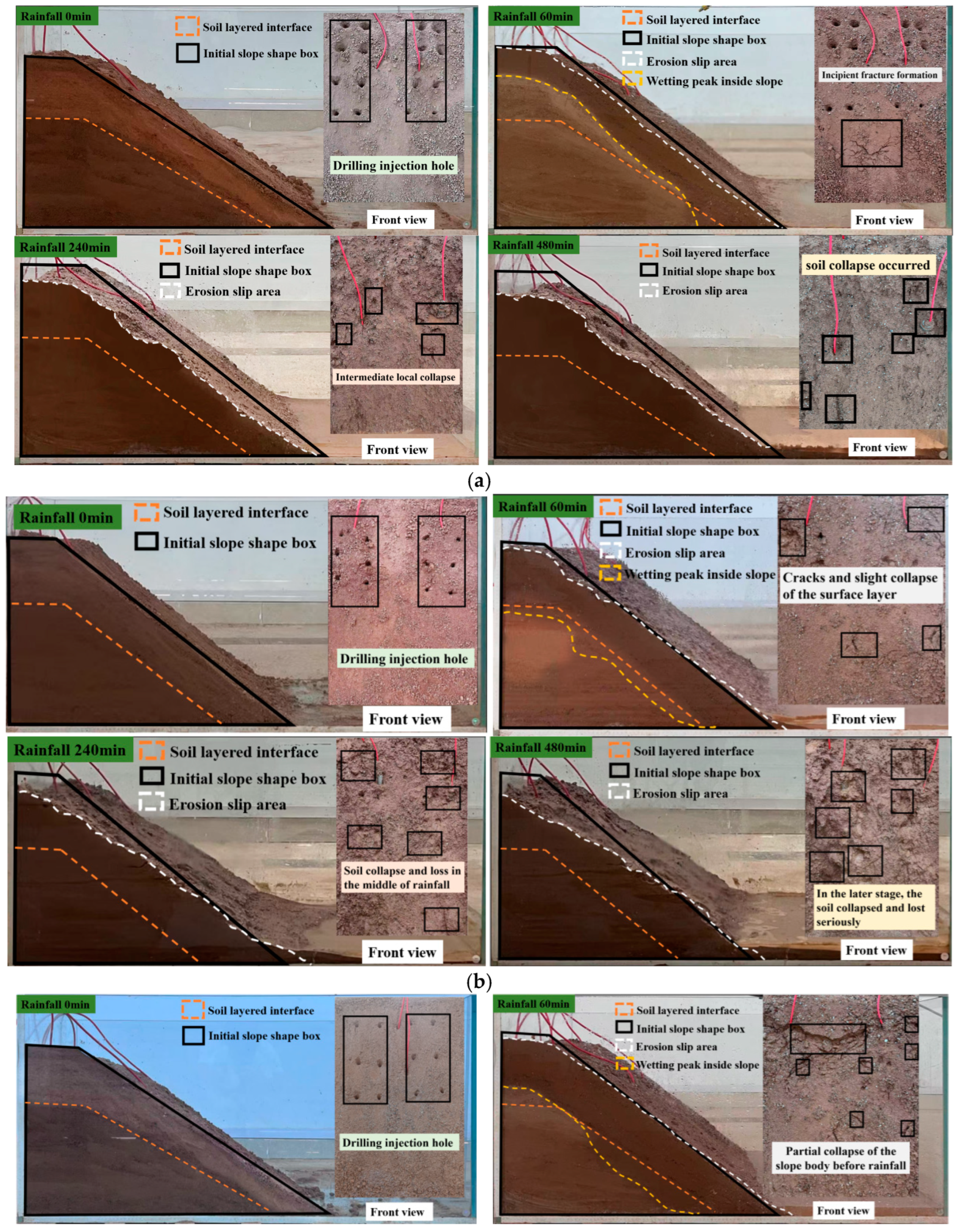
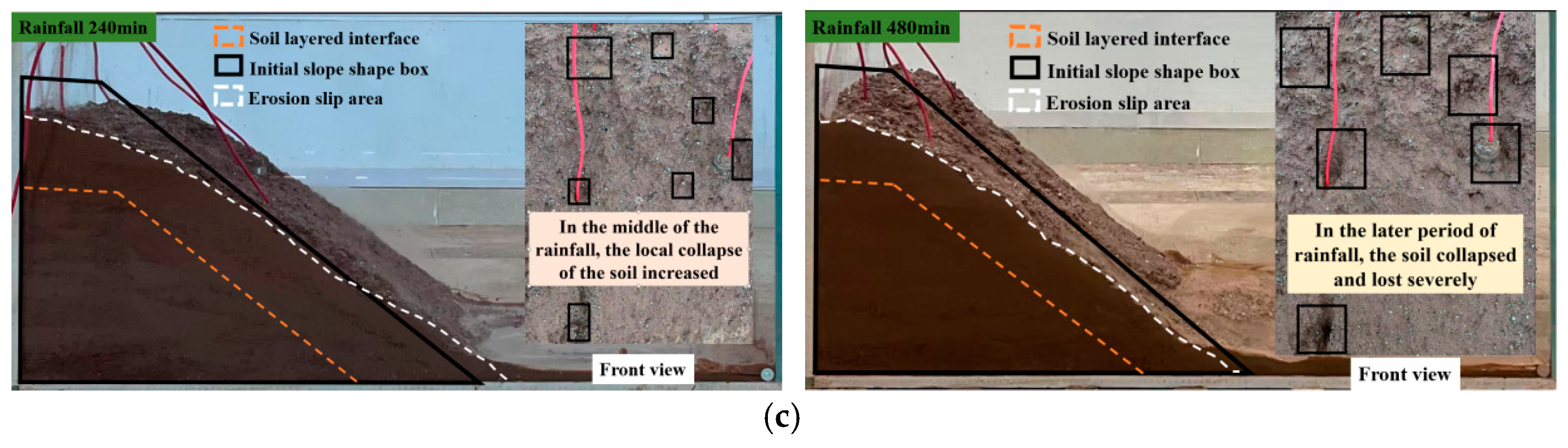
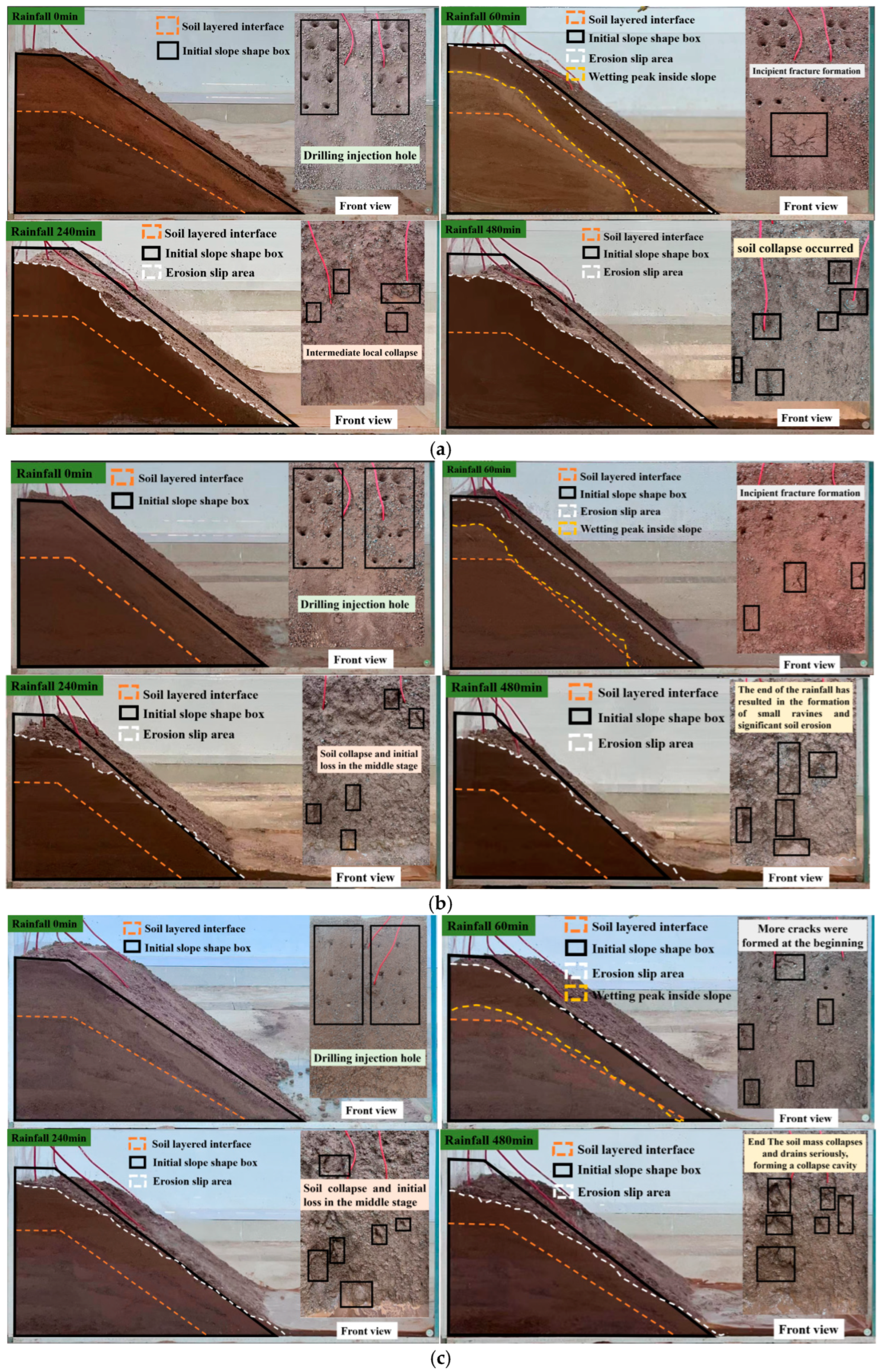
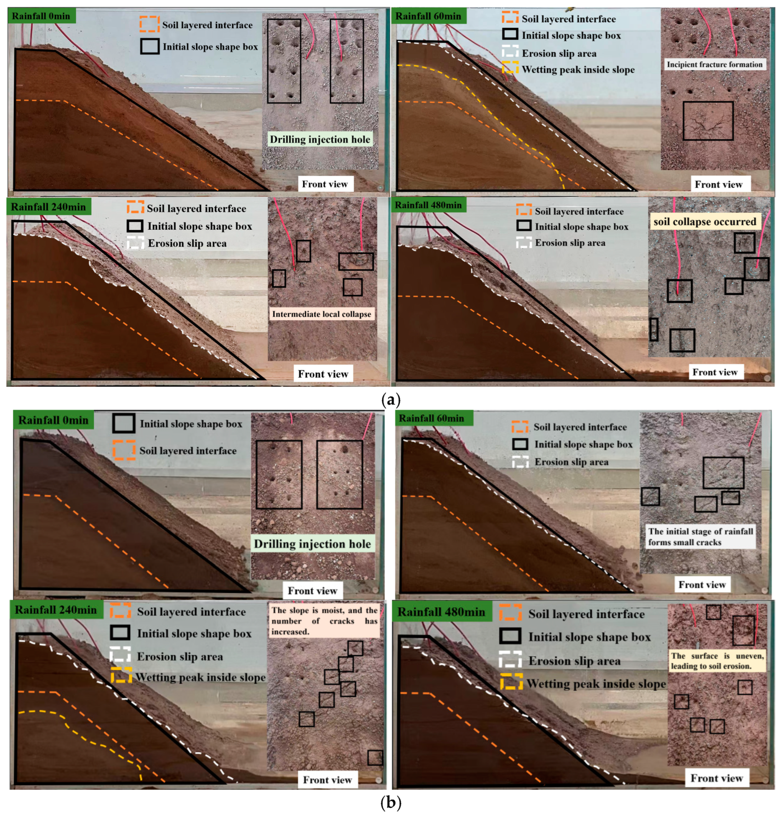
- Variation Law of Slope Morphology
- (2)
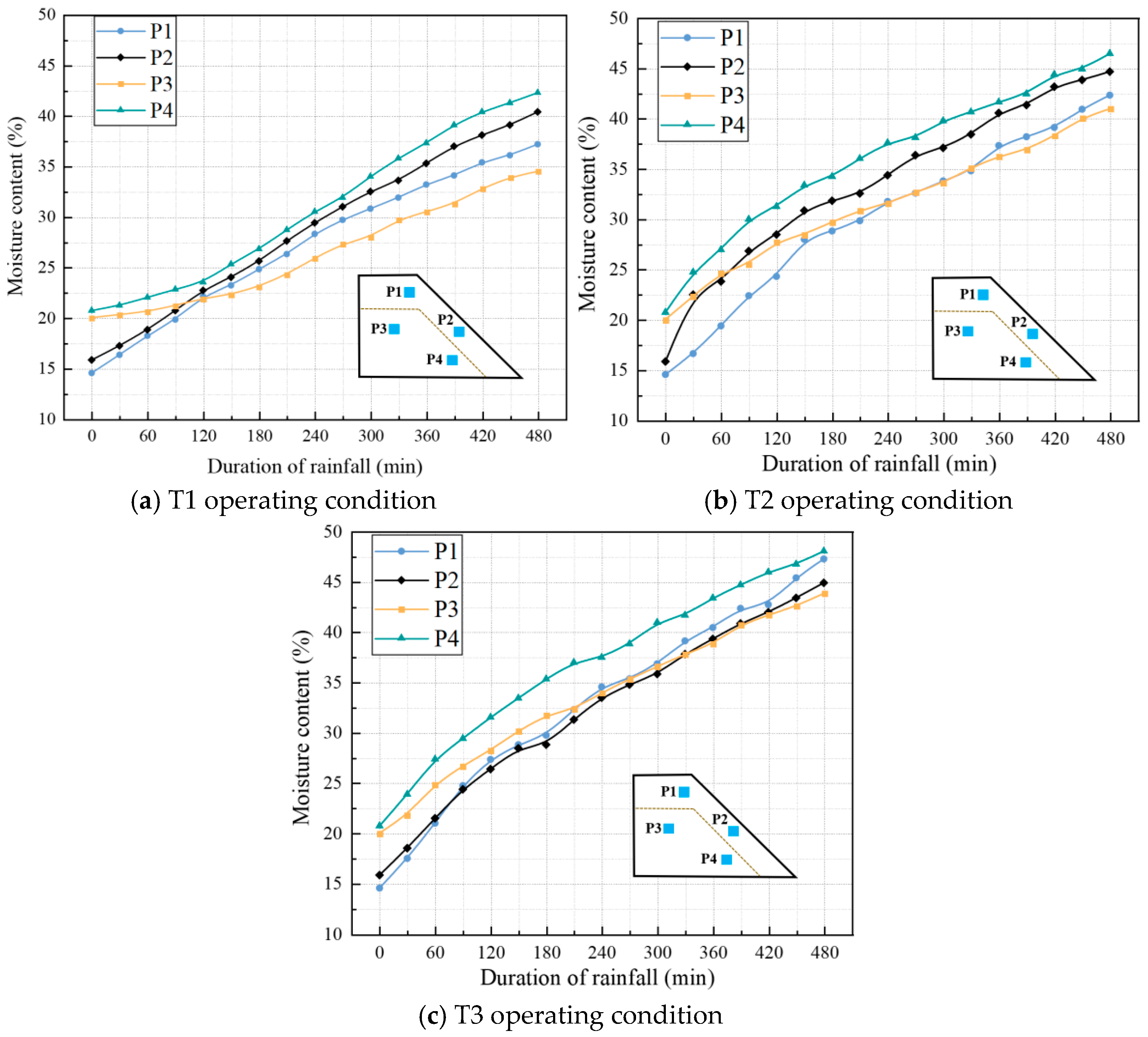
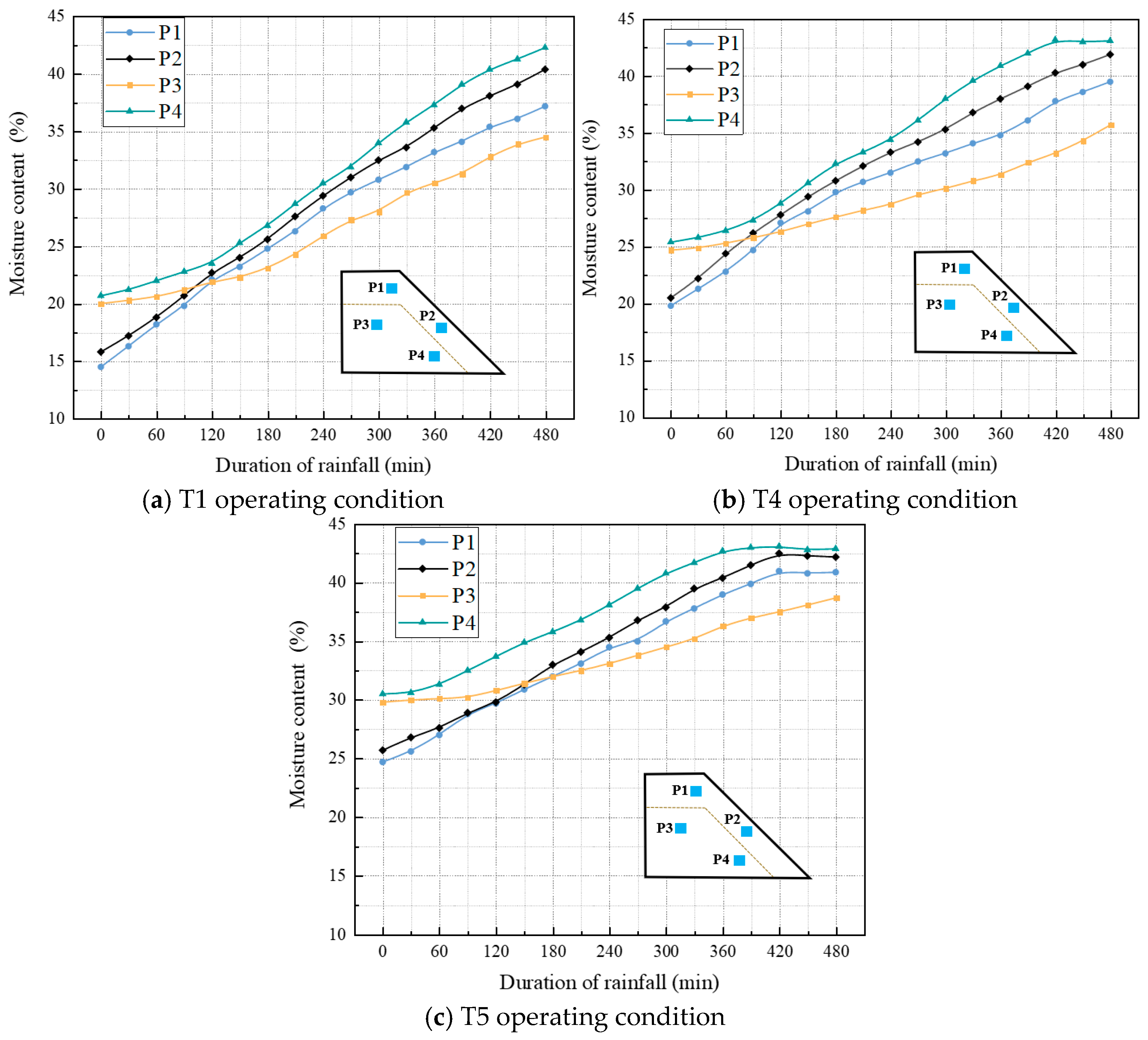
- Variation law of moisture content
- (3)
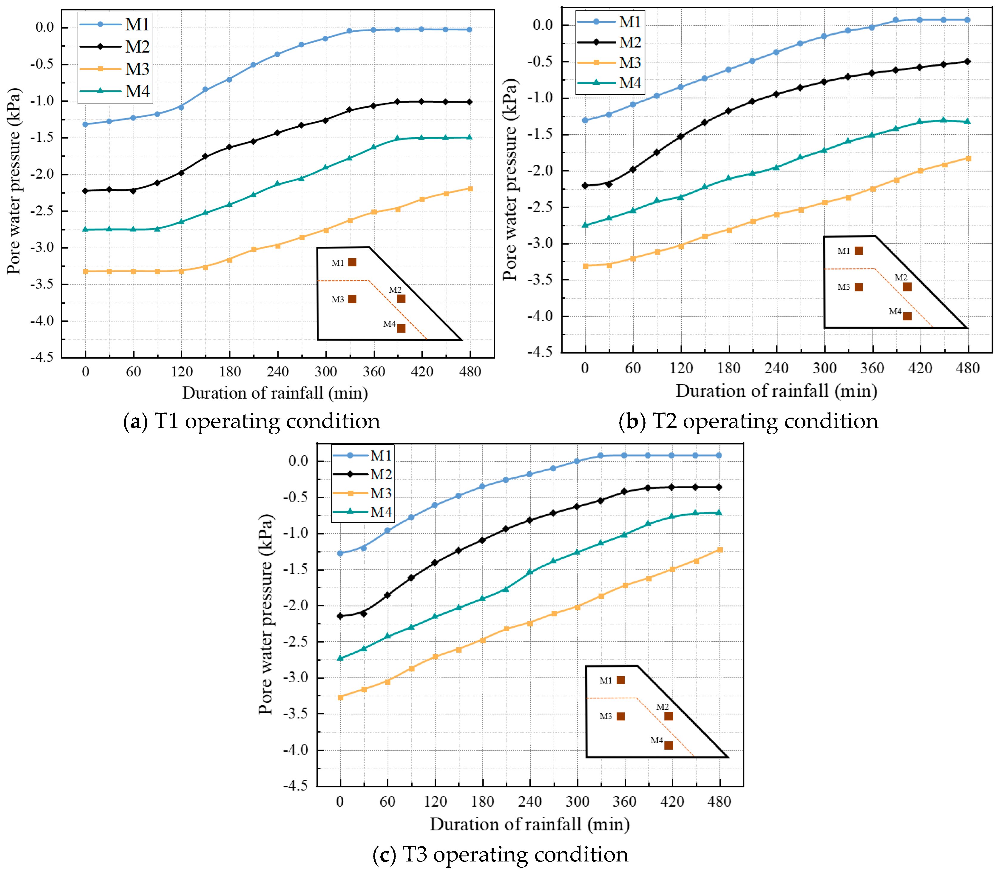
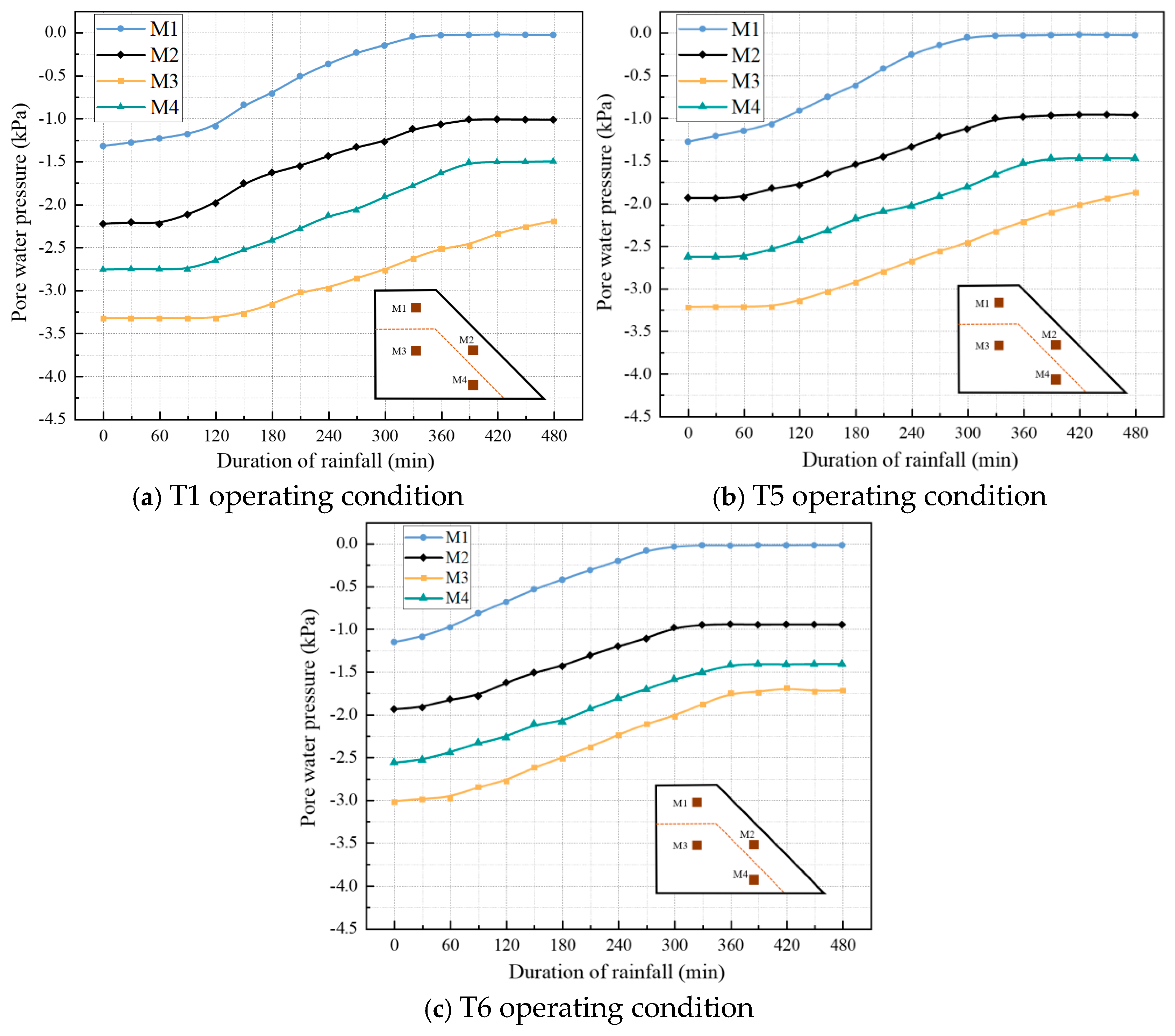
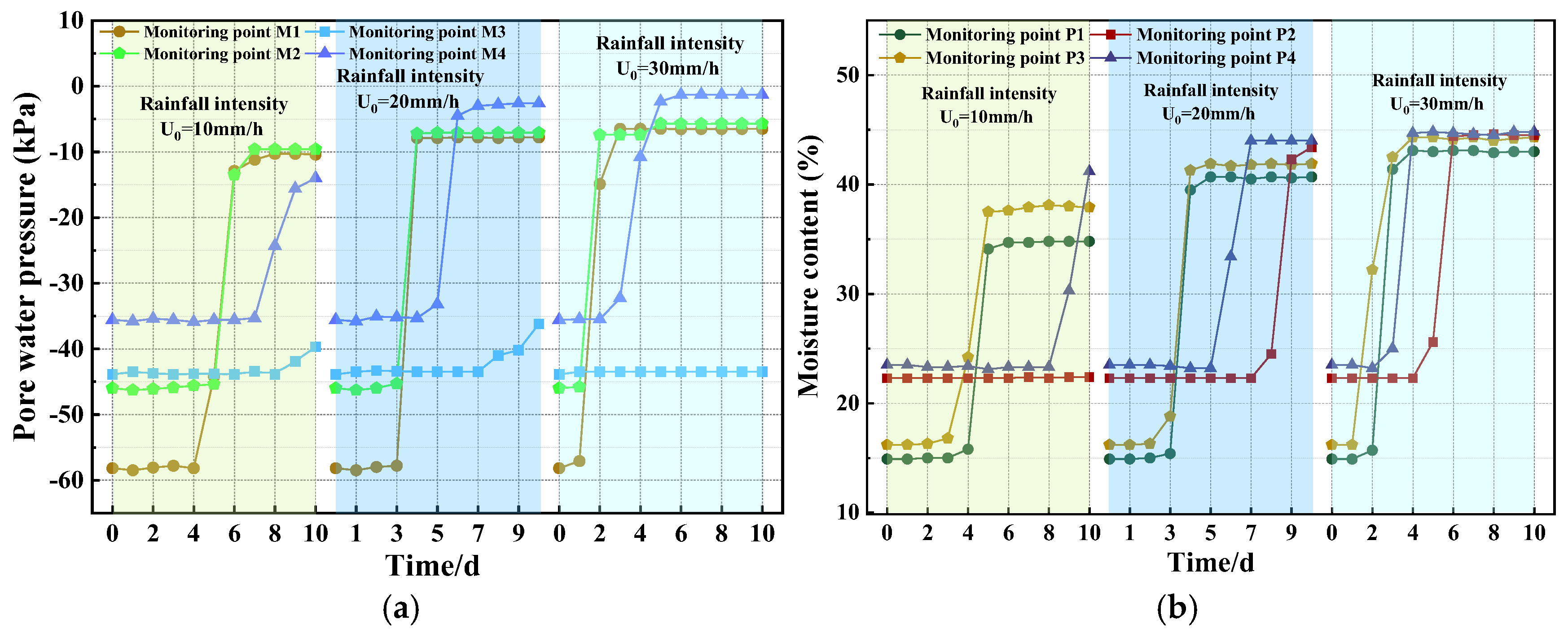
- Variation Law of Pore Water Pressure
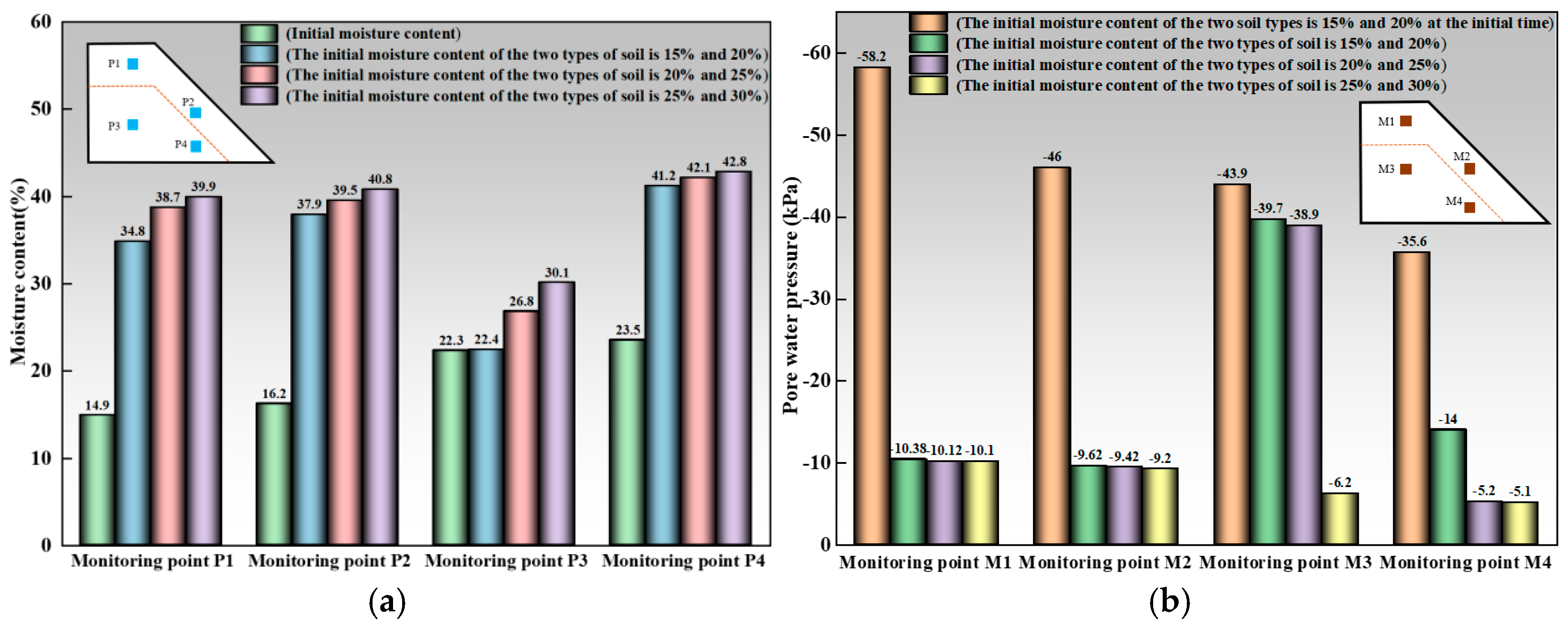
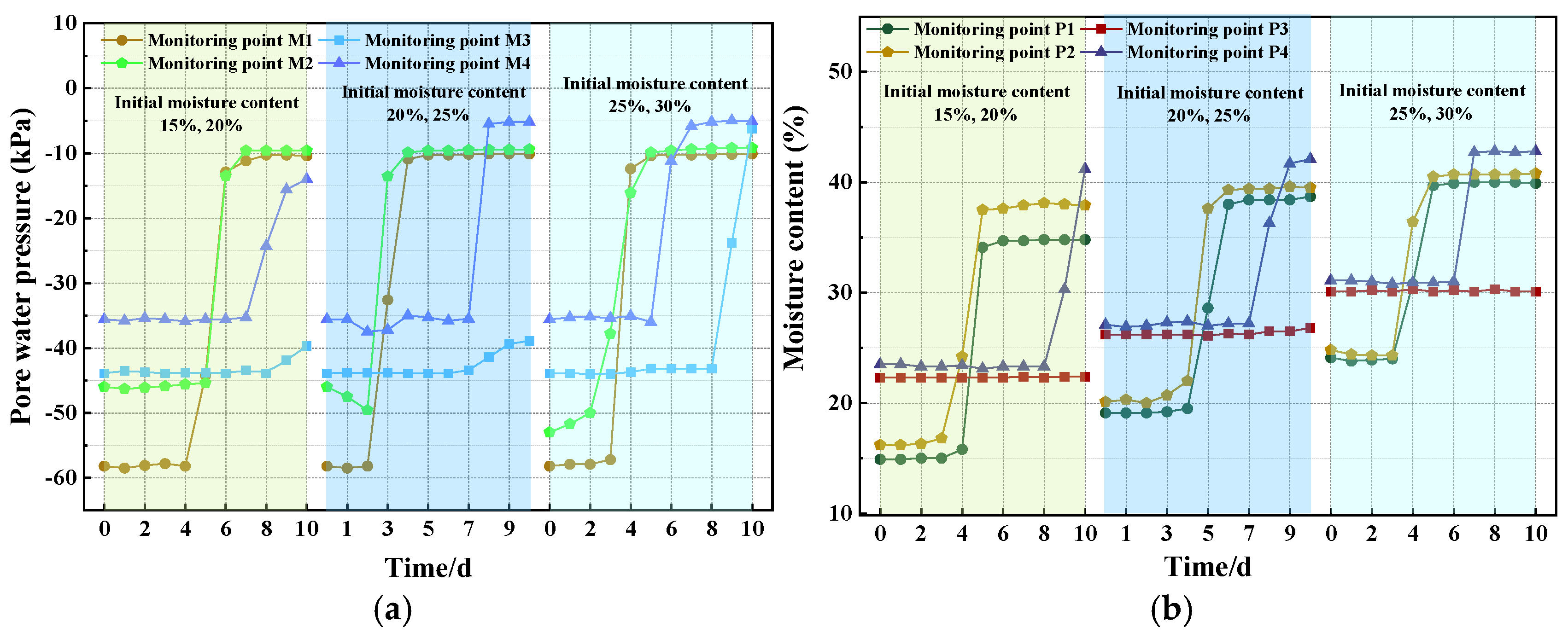
3.2. Different Initial Moisture Content Conditions
- Variation law of slope morphology
- 2.
- Variation law of moisture content
- 3.
- Variation Law of Pore Water Pressure
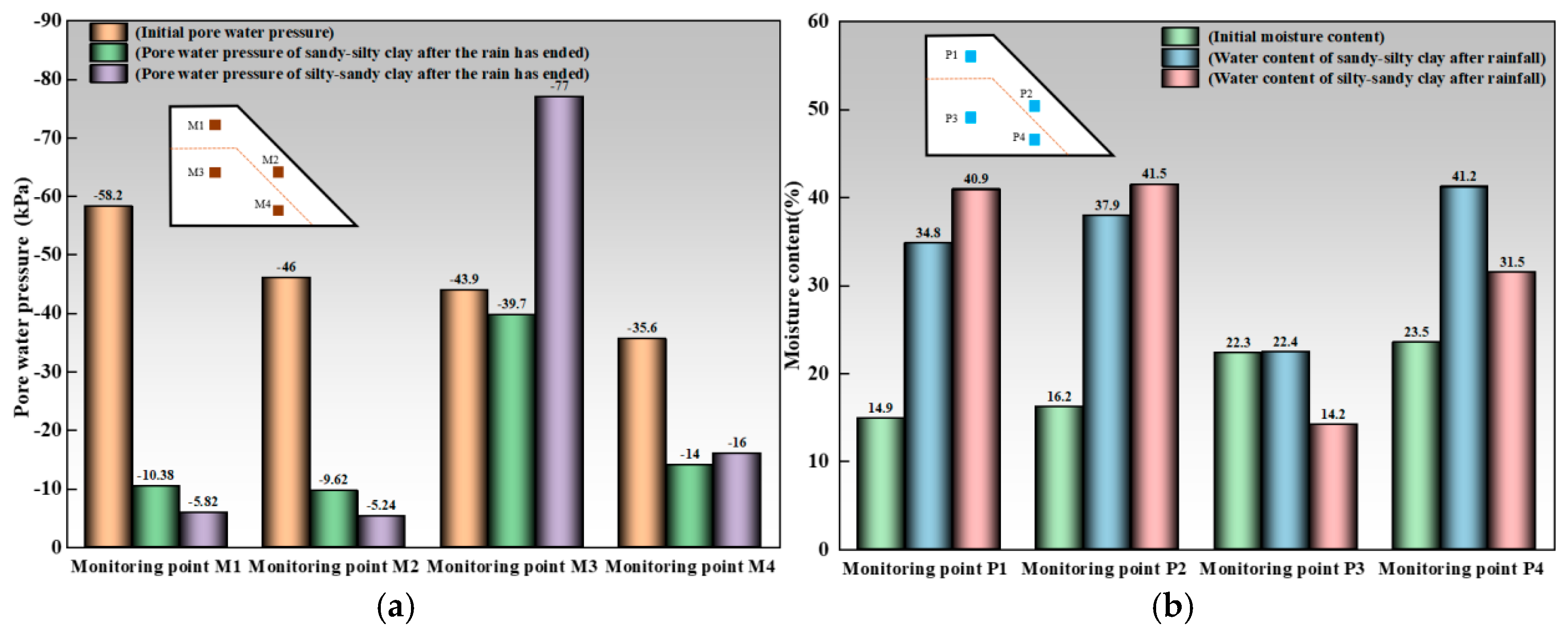
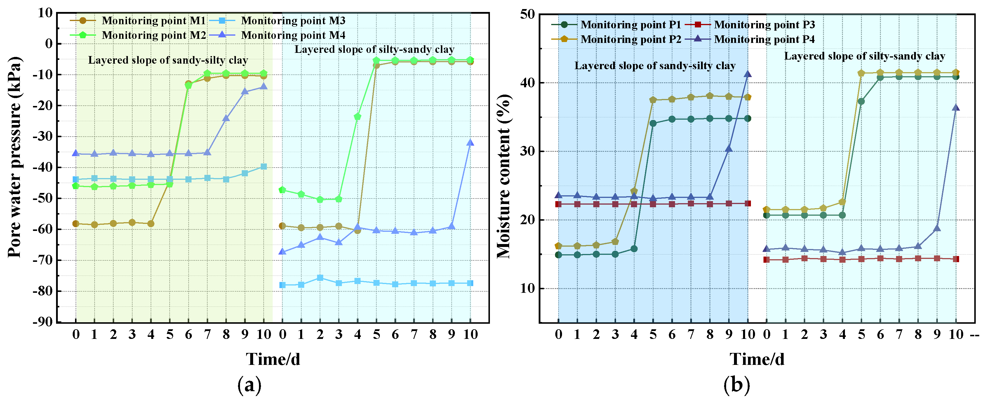
3.3. Different Layering Sequence Conditions
- 4.
- Variation law of slope morphology
- 5.
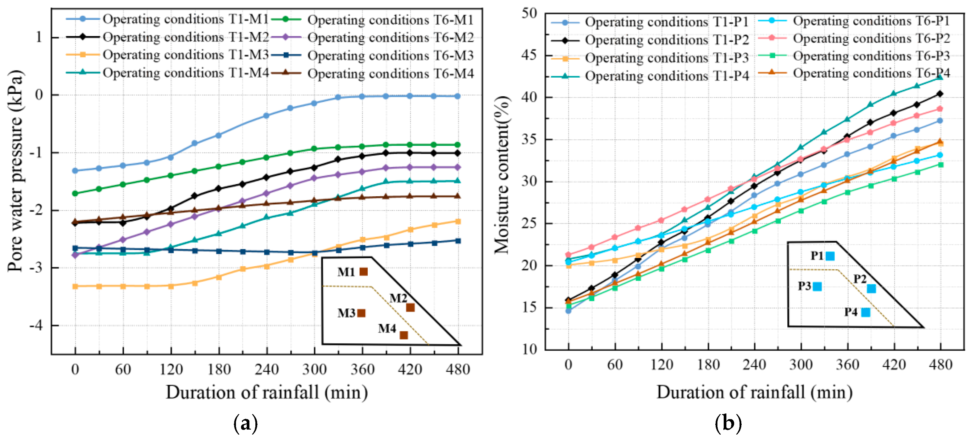
- Variation in water content and pore water pressure
4. Numerical Simulation Analysis
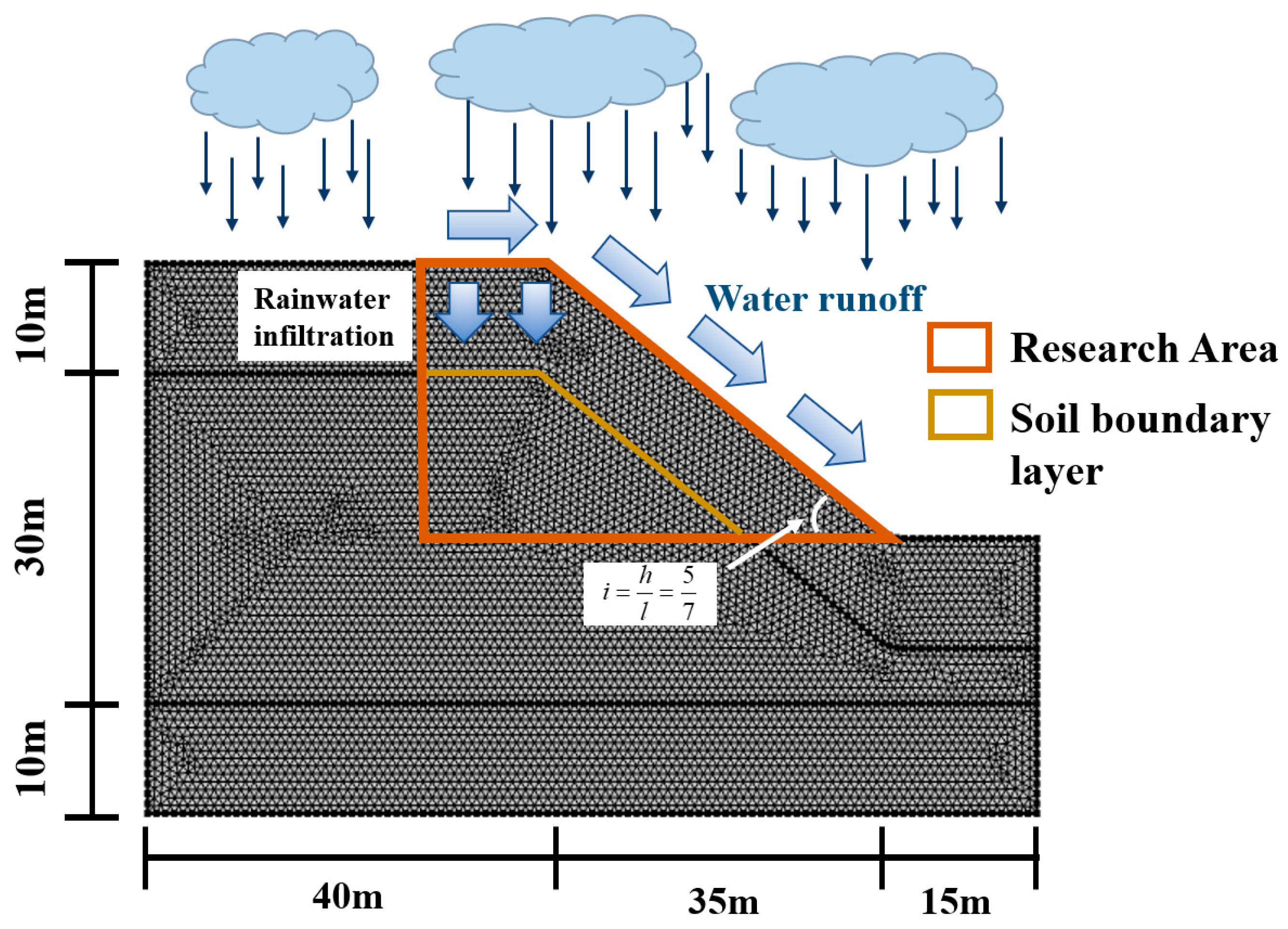
4.1. Establishment of Numerical Model
4.2. Numerical Simulation Condition Design
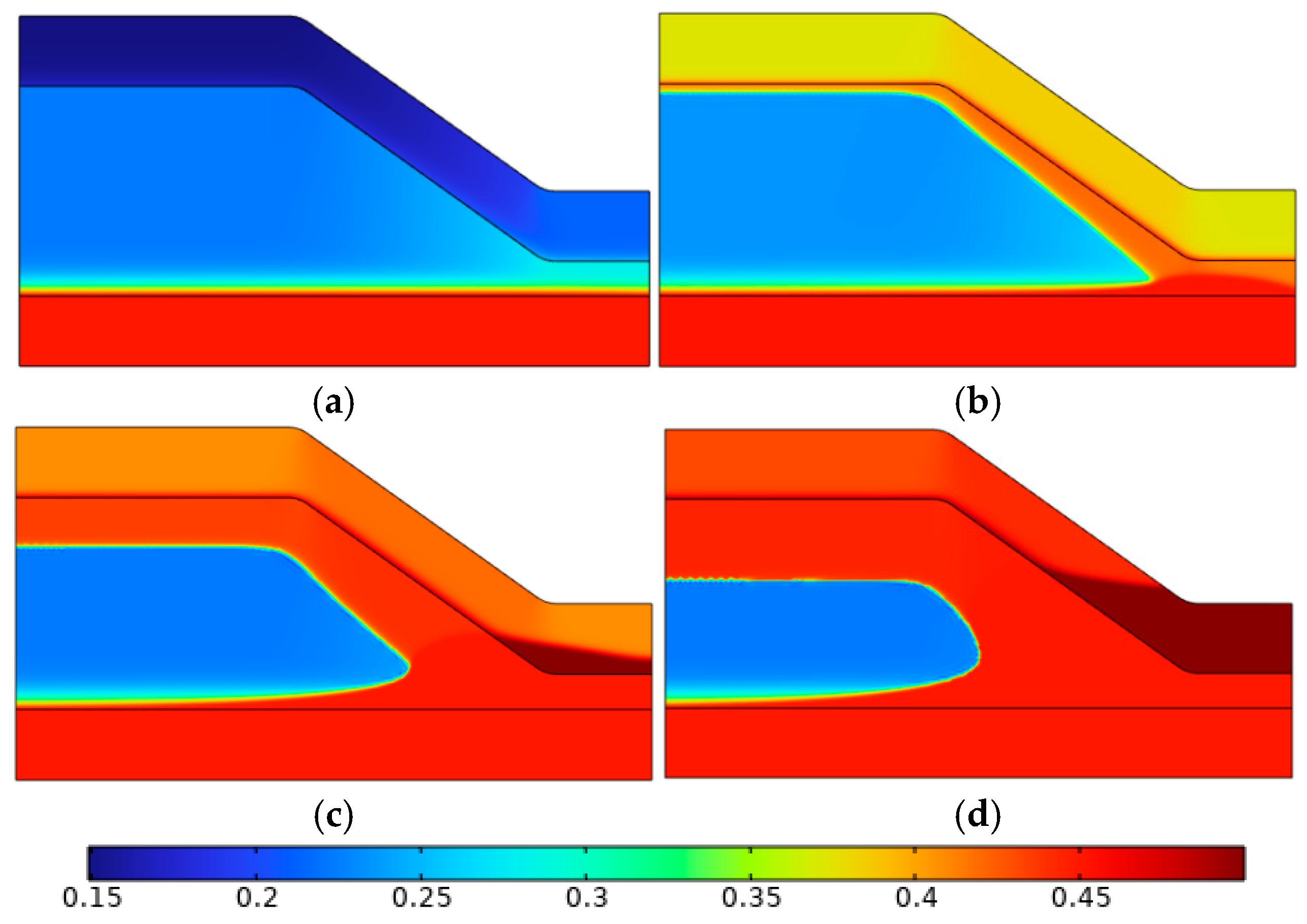
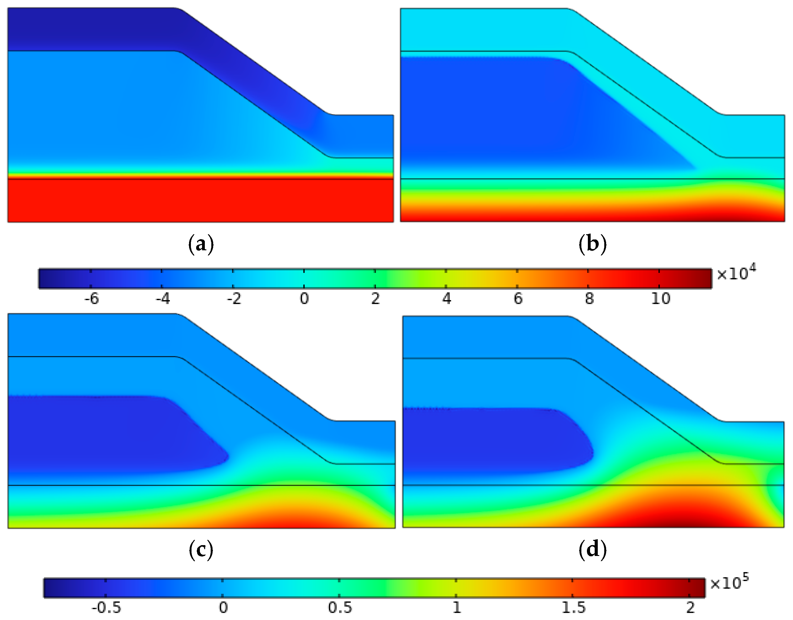
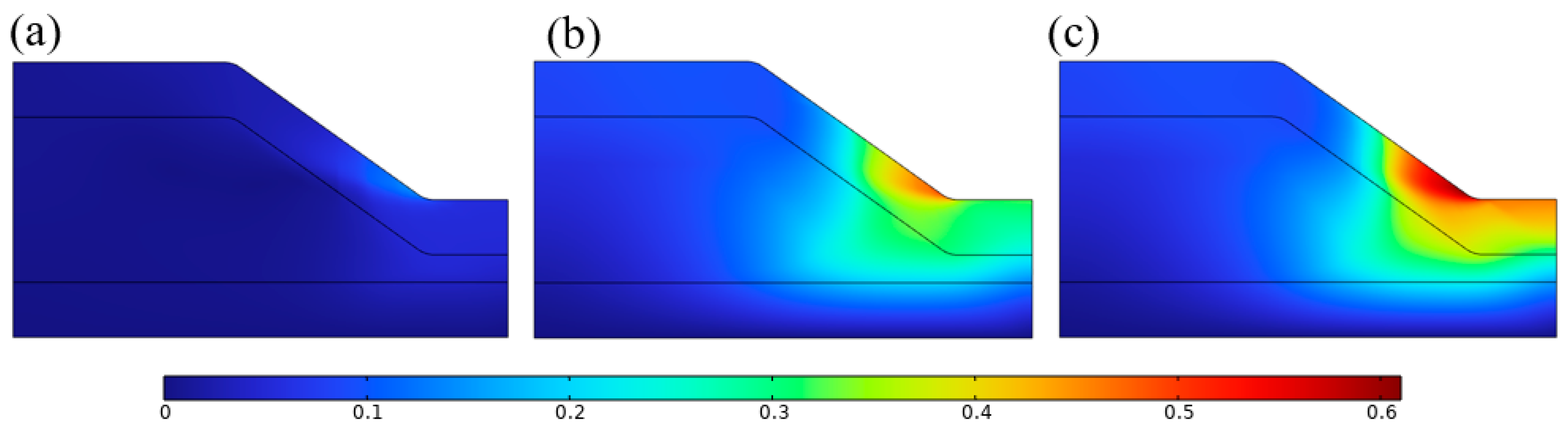
4.3. Different Rainfall Intensities
4.4. Different Initial Moisture Content
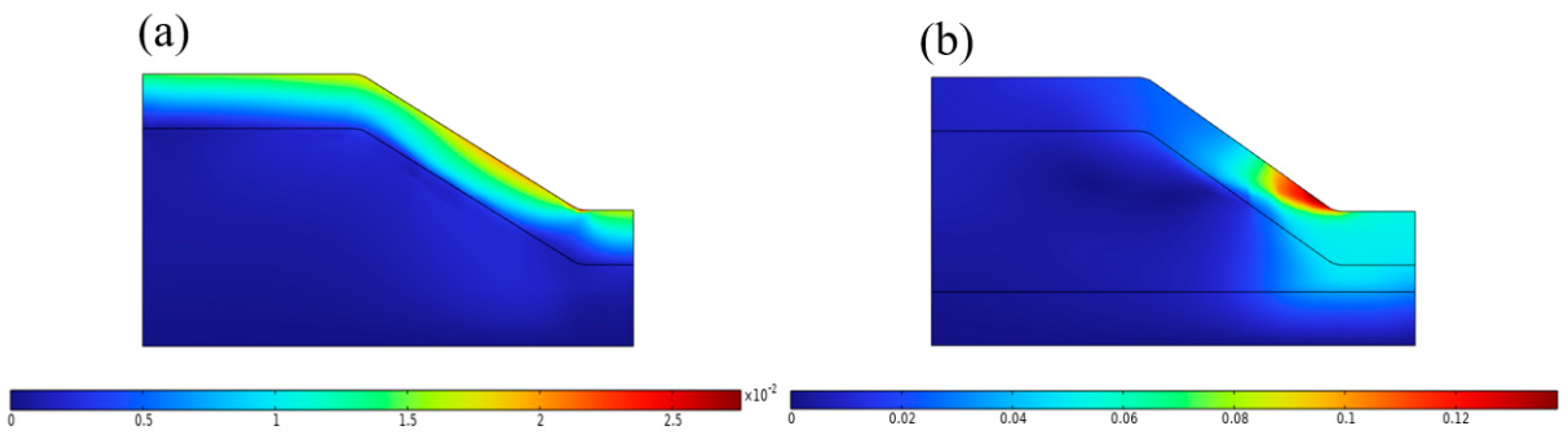
4.5. Different Layering Sequences
5. Comparison and Analysis of the Stability of Layered Slopes
5.1. Strength Theories and Criteria
5.2. Displacement Analysis of Layered Slopes
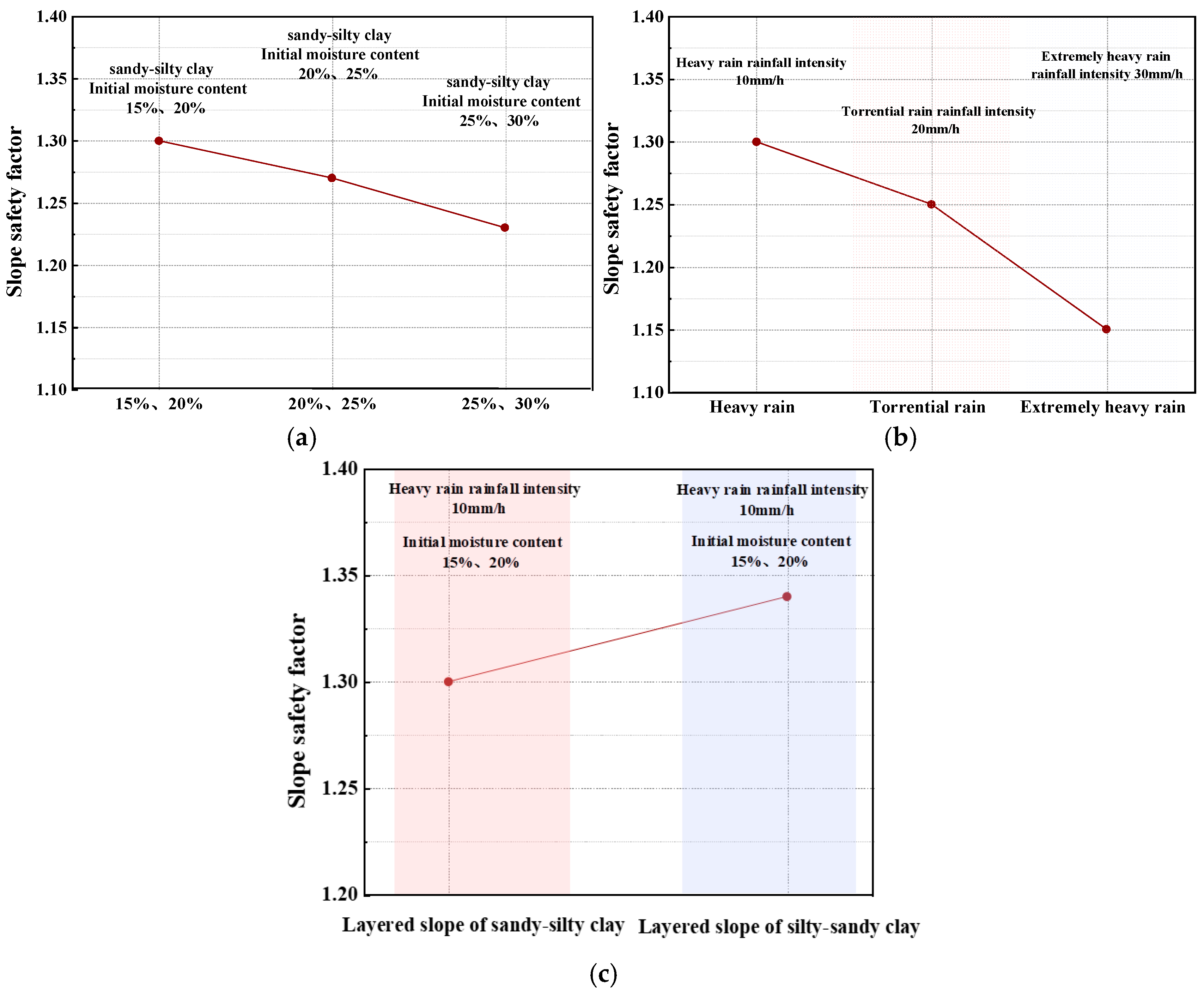
5.3. Analysis of Safety Factor of Layered Slope
6. Conclusions
- (1)
- Injection leaching and rainfall are key driving factors influencing ion-type rare earth mining landslides. The initial moisture contents and rainfall intensities significantly alter the slope’s hydraulic response and failure characteristics. The layering sequence changes the rainfall infiltration path and the distribution pattern of hydraulic coupling, thereby affecting the slope failure mode.
- (2)
- As rainfall intensity increases, the accumulation of pore water pressure and the rise in moisture content significantly intensify, leading to more pronounced water stagnation in the slope. The higher the rainfall intensity, the earlier the slope destabilizes, and the landslide failure range expands significantly. Under heavy rainfall and extreme rainfall conditions, the rate of pore water pressure increase is significantly faster than moderate rainfall conditions.
- (3)
- The initial moisture content reflects the duration and stage of leaching mining. Under conditions of lower initial moisture content, the slope has a stronger ability to absorb water. Rainfall infiltration is rapid, causing significant increases in pore water pressure and moisture content, while the stability is weakened to a lesser extent. In conditions with higher initial moisture content, the soil is close to saturation, resulting in smaller increases in pore water pressure triggered by rainfall. However, the overall reduction in shear strength is more pronounced, making deep slip failure more likely.
- (4)
- In sand–silty clay layered slopes, the high permeability of the upper sandy clay allows rainwater to quickly infiltrate into the silty clay layer, causing the formation of a saturated stagnation zone at the interface, where pore water pressure rises sharply. Landslide failure is mainly concentrated near the interface.
- (5)
- In silty–sand clay layered slopes, the low permeability of the upper silty clay leads to a longer retention time of rainwater at the surface, forming a distinct wet stagnation zone. The slope failure mode is dominated by surface crack propagation and local slippage at the slope toe.
Author Contributions
Funding
Data Availability Statement
Acknowledgments
Conflicts of Interest
References
- Guo, Z.Q.; Zhou, J.R.; Xu, H.; Zhou, K.F.; Jin, J.F. Research Progress on the Weakening of Ion-type Rare Earth Strength and Landslides under Leaching Effects. Chin. Rare Earths 2022, 43, 9–22. [Google Scholar]
- Fan, Y.Q.; Lu, Y.; Jian, W.X.; Niu, G.L. Deformation and Failure Modes of Slopes in Southern Jiangxi and Countermeasures. Geol. Sci. Technol. Inf. 2017, 36, 205–211. [Google Scholar]
- Deng, Y.; Wan, Y.; Kang, S.; Yang, J.; Yu, H. Study on the Influence of Ionic Rare Earth Element Transport Pattern on the Ecological Environment of Slopes and Protection Strategy. Appl. Math. Nonlinear Sci. 2024, 9, 1–15. [Google Scholar] [CrossRef]
- Guo, Z.Q.; Jin, X.F.; Wang, G.S.; Qing, Y.H.; Wang, X.J.; Zhao, K. Basic Theoretical Research on the Leaching Dynamics of Weathered Crust Leachate in Rare Earth Mining. Nonferrous Met. Sci. Eng. 2017, 8, 127–132. [Google Scholar]
- Sarkar, S.; Chakraborty, M. Stability Analysis for Two-layered Slopes by Using the Strength Reduction Method. Int. J. Geo-Eng. 2021, 12, 24. [Google Scholar] [CrossRef]
- Daraei, A.; Zare, S. Effect of Water Content Variations on Critical and Failure Strains of Rock. KSCE J. Civ. Eng. 2018, 22, 3331–3339. [Google Scholar] [CrossRef]
- Li, Y.; Xue, K.; Zhao, Y.; Wang, C.; Bi, J.; Wang, T.; Wang, S.; Zhang, B. Study on the Stability and Disaster Mechanism of Layered Soil Slopes under Heavy Rain. Bull. Eng. Geol. Environ. 2023, 82, 272. [Google Scholar] [CrossRef]
- Tang, X.Z.; Li, M.N.; Yang, D. Landslides in Ion-type Rare Earth In-situ Leaching Mining Areas and Its Countermeasures. Met. Mines 2000, 289, 6–8. [Google Scholar]
- Rao, R.; Li, M.C.; Zhang, S.B.; Rao, Y.Z.; Zhong, J.M. Landslide Characteristics and Prevention and Control Experiments in Ion-type Rare Earth In-situ Leaching Mining Areas. Rare Earths 2016, 37, 26–31. [Google Scholar]
- Deng, W.J.; Rao, Y.Z.; Wang, D.; Xu, W.F.; Chen, J.L. Study on the Influence of Rainwater Infiltration on the Stability of Ion-type Rare Earth Slopes. Min. Res. Dev. 2019, 39, 6–12. [Google Scholar]
- Li, S.H.; Jiang, Z.L.; Que, Y.; Chen, X.; Ding, H.; Liu, Y.; Dai, Y.; Xue, B. Water Field Distribution Characteristics under Slope Runoff and Seepage Coupled Effect Based on the Finite Element Method. Water 2021, 13, 3569. [Google Scholar] [CrossRef]
- Geng, J.; Wang, Z.; Lan, X.; Li, X.; Zhang, D. Numerical Simulation and Safety Distance Analysis of Slope Instability of Ionic Rare Earth Tailings in Different Rainy Seasons. Geomat. Nat. Hazards Risk 2023, 14, 2277127. [Google Scholar] [CrossRef]
- Dai, G.Y.; Zhang, F.; Wang, Y. Stability Analysis of Layered Slopes in Unsaturated Soils. Front. Struct. Civ. Eng. 2022, 16, 378–387. [Google Scholar] [CrossRef]
- Jiang, S.H.; Yuan, Z.R.; Liu, X.; Huang, J.S.; Zhou, C.B. Rainfall Infiltration Model and Slope Stability Analysis Considering Transitional Layer Spatial Variability. Chin. J. Geotech. Eng. 2024, 46, 1–9. [Google Scholar]
- Jiang, S.H.; Liu, X.; Huang, F.M.; Huang, J.S. Rainfall Infiltration Slope Instability Mechanism and Reliability Analysis Considering Multi-parameter Spatial Variability. Chin. J. Geotech. Eng. 2020, 42, 900–907. [Google Scholar]
- Jiang, S.H.; Liu, X.; Huang, J.S.; Zhou, C.B. Improved Green-Ampt Model for Rainfall Infiltration Analysis in Multi-layer Heterogeneous Slopes. Chin. J. Geotech. Eng. 2024, 46, 1177–1186. [Google Scholar]
- Zhou, X.P.; Zhu, B.Z.; Juang, C.H.; Wong, L.N.Y. Stability Analysis of a Layered-Soil Slope Based on Random Field. Bull. Eng. Geol. Environ. 2019, 78, 2611–2625. [Google Scholar] [CrossRef]
- Ren, L.D.; Huang, M.B.; Fan, J. Research on the Water Holding Capacity of Different Types of Layered Soils. Trans. Chin. Soc. Agric. Eng. 2013, 29, 105–111. [Google Scholar]
- Li, Y.; Ren, X.; Horton, R. Influence of Soil Texture and Interlayer Position on Rainwater Infiltration in Layered Soils. J. Drain. Irrig. Mach. Eng. 2012, 30, 485–490. [Google Scholar]
- Li, A.J.; Merifield, R.S.; Lyamin, A.V. Limit Analysis Solutions for Three-Dimensional Undrained Slopes. Comput. Geotech. 2009, 36, 1330–1351. [Google Scholar] [CrossRef]
- Li, A.J.; Merifield, R.S.; Lyamin, A.V. Three-Dimensional Stability Charts for Slopes Based on Limit Analysis Methods. Can. Geotech. J. 2010, 47, 1316–1334. [Google Scholar] [CrossRef]
- Shiau, J.S.; Merifield, R.S.; Lyamin, A.V.; Sloan, S.W. Undrained Stability of Footings on Slopes. Int. J. Geomech. 2011, 11, 381–390. [Google Scholar] [CrossRef]
- Qian, Z.G.; Li, A.J.; Merifield, R.S.; Lyamin, A.V. Slope Stability Charts for Two-Layered Purely Cohesive Soils Based on Finite-Element Limit Analysis Methods. Int. J. Geomech. 2014, 15, 06014022. [Google Scholar] [CrossRef]
- Liu, S.Q.; Xu, S.H.; Li, X.P.; Yan, Y.F.; Zhao, Y.C.; Liu, J.L. Research Progress on the Effects of Soil Configuration on Soil Water and Nitrogen Transport. Soil 2016, 48, 219–224. [Google Scholar]
- Tsia, C. Modeling of Layered Infinite Slope Failure Triggered by Rainfall. Environ. Earth Sci. 2013, 68, 1429–1434. [Google Scholar] [CrossRef]
- Guo, Z.Q.; Liu, Q.Q.; Liu, L.F.; Wang, H.X.; Liu, Y.S. Experimental Study on Landslide Simulation of Ion-Type Rare Earth Mine Under Rainfall-Leaching Condition [J]. Non Metals 2025, 15, 129–139. [Google Scholar]
- Fan, Y.W.; Huang, N.; Ma, X.Y. Application of HYDRUS-1D to Simulate Infiltration Characteristics of Sandy Interlayer Soils. Soil 2016, 48, 193–200. [Google Scholar]
- Chen, R.X.; Fu, H.P.; Song, Y.; Wang, T.W.; Gao, B. Landslide Characteristics and Genesis in Rare Earth Leaching Mining Areas. Jiangxi Build. Mater. 2021, 1, 183–185. [Google Scholar]
- Ziadat, F.M.; Taimeh, A.Y. Effect of Rainfall Intensity, Slope, Land Use, and Antecedent Soil Moisture on Soil Erosion in an Arid Environment. Land Degrad. Dev. 2013, 24, 582–590. [Google Scholar] [CrossRef]
- Shen, H.O.; Zheng, F.L.; Wen, L.L.; Han, Y.; Hu, W. Impacts of Rainfall Intensity and Slope Gradient on Rill Erosion Processes at Loessial Hillslopes. Soil Tillage Res. 2016, 155, 429–436. [Google Scholar] [CrossRef]
- Zhang, X.; Wang, Z.; Chen, W. Optimisation of synergistic ventilation between dust and gas in a gas tunnel. Sci. Rep. 2024, 14, 27582. [Google Scholar] [CrossRef] [PubMed]
- Liu, C.D.; Zhang, R.; Wang, Z.; Zhang, X.P.; Wang, H. Research on the fire extinguishing performance of new gel foam for preventing and controlling the spontaneous combustion of coal gangue. Environ. Sci. Pollut. Res. 2023, 30, 88548–88562. [Google Scholar] [CrossRef] [PubMed]
- Shao, W.; Bogaard, T.; Bakker, M. How to Use COMSOL Multiphysics for Coupled Dual-Permeability Hydrological and Slope Stability Modeling. In Proceedings of the Third Italian Workshop on Landslides; ScienceDirect: Naples, Italy, 2014. [Google Scholar]
- Yao, Y.Q.; Zeng, R.Q.; Ma, J.H.; Meng, X.P. Rainfall Infiltration Slope Reliability Analysis Considering Dominant Flow Effects. Rock Soil Mech. 2022, 43, 2305–2316. [Google Scholar]
- Dou, Z.; Liu, Y.M.; Zhou, Z.F.; Zhuang, C.; Wei, Y.B. Improvement of Rainfall Boundary Treatment for Single and Dual Permeability Media. Rock Soil Mech. 2022, 43, 789–798. [Google Scholar]
- Van Genuchten, M.T. A Closed-Form Equation for Predicting the Hydraulic Conductivity of Unsaturated Soils. Soil Sci. Soc. Am. J. 1980, 44, 892–898. [Google Scholar] [CrossRef]
- Fredlund, D.G.; Rahardjo, H. Soil Mechanics for Unsaturated Soils; John Wiley & Sons: Ottawa, ON, Canada, 1993. [Google Scholar]
- Gao, F.; Li, X.J.; Chi, M.J. Stability Analysis of Single and Double-Sided Slopes Based on the Finite Element Strength Reduction Method. J. Eng. Geol. 2020, 28, 650–657. [Google Scholar]


| Soil | Young’s Modulus E/ MPa | Poisson Ratio μ | Moisture Content ω/ % | Porosity n | Unit Weight γ/kN/m3 | Saturation Permeability Coefficient Ks/ m/s | Cohesion c/ kPa | Internal Friction Angle φ/ ° |
|---|---|---|---|---|---|---|---|---|
| Silty clay | 2.23 | 0.3 | 21.23 | 0.45 | 15.6 | 1.25 × 10⁻⁵ | 24.3 | 18 |
| Sandy clay | 6 | 0.3 | 12.31 | 0.50 | 17.5 | 4.5 × 10⁻⁵ | 18.2 | 25 |
| Test Number | T1 | T2 | T3 | T4 | T5 | T6 |
|---|---|---|---|---|---|---|
| Slope Layering Order | Sandy–silty clay | Sandy–silty clay | Sandy–silty clay | Sandy–silty clay | Sandy–silty clay | Silty–sandy clay |
| Rainfall intensity (mm/h) | 30 | 60 | 90 | 30 | 30 | 30 |
| Initial moisture content of sandy clay (%) | 15 | 15 | 15 | 20 | 25 | 15 |
| Initial moisture content of silty clay (%) | 20 | 20 | 20 | 25 | 30 | 20 |
| Duration of rainfall (min) | 480 | 480 | 480 | 480 | 480 | 480 |
| Test Number | Type of Precipitation | Rainfall Intensity/(mm·h−1) | Types of Layered Slope Models | Initial Moisture Content of Two Types of Soil. (%) | Duration of Rainfall/d |
|---|---|---|---|---|---|
| Q1 | Heavy rain | 10 | Sandy–silty clay | 15, 20 | 10 |
| Q2 | Torrential rain | 20 | Sandy–silty clay | 15, 20 | 10 |
| Q3 | Extremely heavy rain | 30 | Sandy–silty clay | 15, 20 | 10 |
| Q4 | Heavy rain | 10 | Sandy–silty clay | 20, 25 | 10 |
| Q5 | Heavy rain | 10 | Sandy–silty clay | 25, 30 | 10 |
| Q6 | Heavy rain | 10 | Silty–sandy clay | 15, 20 | 10 |
Disclaimer/Publisher’s Note: The statements, opinions and data contained in all publications are solely those of the individual author(s) and contributor(s) and not of MDPI and/or the editor(s). MDPI and/or the editor(s) disclaim responsibility for any injury to people or property resulting from any ideas, methods, instructions or products referred to in the content. |
© 2025 by the authors. Licensee MDPI, Basel, Switzerland. This article is an open access article distributed under the terms and conditions of the Creative Commons Attribution (CC BY) license (https://creativecommons.org/licenses/by/4.0/).
Share and Cite
Guo, Z.; Liu, Y.; Liu, Q.; Zhong, M.; Liu, Q. Model Test and Numerical Analysis of Landslides in Layered Ion-Type Rare Earth Ore Under Rainfall and Mineral Leaching Conditions. Water 2025, 17, 1469. https://doi.org/10.3390/w17101469
Guo Z, Liu Y, Liu Q, Zhong M, Liu Q. Model Test and Numerical Analysis of Landslides in Layered Ion-Type Rare Earth Ore Under Rainfall and Mineral Leaching Conditions. Water. 2025; 17(10):1469. https://doi.org/10.3390/w17101469
Chicago/Turabian StyleGuo, Zhongqun, Yanshuo Liu, Qiqi Liu, Manqiu Zhong, and Qiangqiang Liu. 2025. "Model Test and Numerical Analysis of Landslides in Layered Ion-Type Rare Earth Ore Under Rainfall and Mineral Leaching Conditions" Water 17, no. 10: 1469. https://doi.org/10.3390/w17101469
APA StyleGuo, Z., Liu, Y., Liu, Q., Zhong, M., & Liu, Q. (2025). Model Test and Numerical Analysis of Landslides in Layered Ion-Type Rare Earth Ore Under Rainfall and Mineral Leaching Conditions. Water, 17(10), 1469. https://doi.org/10.3390/w17101469