Abstract
The characteristics of linear hydroelastic waves propagating in a channel covered with compressed ice are investigated. The channel has a rectangular cross-section and is assumed to be infinite in length. The fluid in the channel is non-viscous and incompressible; its flow is potential. The ice cover is modelled by an elastic plate of constant thickness frozen to the channel walls. Principal attention is paid to the investigation of the influence of ice compression on the parameters of hydroelastic waves. The problem is solved in a coupled hydroelastic formulation. The profiles of propagating waves in the channel are sought in the form of series on the normal modes of a dry plate. The modes are defined analytically through trigonometric and hyperbolic functions. It is shown that compression in the longitudinal and transverse directions has different effects on the dispersion relations of these hydroelastic waves, their shape and phase, as well as on the critical velocities and strains distribution.
1. Introduction
The problem of flexural-gravity waves in ice sheets has been actively studied in recent decades in connection with climate warming, which has caused the melting of ice at high latitudes and opened up the possibility of using the Northern Sea Route during several months of the year (see [1], for example). The majority of papers on flexural-gravity wave propagation, starting with Greenhill [2], Kheysin [3,4] and Nevel [5], have been conducted for ice sheets of infinite extent. The flow beneath the ice plate was assumed potential. The deflection of the ice cover was described by the linear equation of elastic plate. The thickness of the plate was constant and negligible compared with the depth of the fluid. A detailed review of research on wave loads on a floating ice plate carried out up to 1996 is given in [6]. The investigation of waves in an unbounded ice sheet has continued to the present day. The effects of steady or accelerated load motion over or under the ice sheet was investigated in [7,8,9,10,11,12,13,14,15,16,17,18]. The presence of underwater obstacles, walls, legs of bridges or oil platforms and other engineering structures was considered in [19,20,21,22,23,24,25]. The influence on propagation of flexural-gravity waves and formation of cracks are studied in [26,27,28,29]. In addition, ice sheet models are becoming more complex. Visco-elastic or poro-elastic floating plate models are being considered [30,31,32,33,34]. Nonlinear models are also being developed [35,36,37,38,39].
However, most ice tanks in which scientific and technical experiments with floating ice cover are conducted have a finite size and rectangular cross-section. The hydroelastic waves in such a channel are combinations of waves propagating along the channel and sloshing waves across the channel, due to multiple reflections from the channel walls. Hence, the study of the wave characteristics in channels and their distinction from waves in infinite sheets seems to be very relevant. In addition, channels are a simplified model of rivers. In the northern countries, rivers are frozen in winter and can be used for the transportation of peoples and goods, providing accessibility to remote areas. This leads to many questions related to the conditions of preservation and/or destruction of the ice cover, including under the influence of propagating waves and moving loads [40,41,42,43]. It is well known that boundary conditions on the channel walls significantly affect the results of these studies (see [19,21,24], for example).
It was shown in papers [44,45,46,47] that the presence of the channel walls leads to the formation of waves of various forms across the channel. The number of these propagating waves is countable in linear theory, but in reality only the first few are visible, due to energy dissipation on the ice sheet or in the fluid. Each of these forms depends on the channel size, ice thickness and boundary conditions and has its own dispersion curve, phase and group, and, consequently, critical velocities. In the papers (except for [46]), the solution to the problem was constructed by the method of normal modes, which were determined analytically. Using this method, the problem of periodic waves was reduced to an infinite system of linear equations with zero right-hand side. By reduction, the eigenvalues of this system were found and the dispersion relations, forms of waves, their group and phase velocities were determined with their help.
In papers [48,49,50], the motion of a load along an ice-covered channel was considered for a viscoelastic ice plate. The wave field from a moving load at large times was determined in the framework of the elastic plate model [51]. These papers showed the importance of the presence of several dispersion curves and critical velocities for each of them on the formation of the hydroelastic wave response to the moving load. In these pieces of research, the problems after the Fourier transform at each time instant was also solved using the normal mode method. The deflection of the ice cover and the bending stresses in it were obtained numerically by inverse Fourier transform. The influence of the physical parameters of the problem, such as the speed of moving load, the width and depth of the channel, the damping coefficient and others on the hydroelastic response of the ice plate was studied.
In papers [52,53,54,55,56,57,58,59], the effect of ice compressibility on a boundless ice cover was studied. In papers [4,53], it was mentioned that the ice cover can be compressed by wind or currents. Although the values of this compression in nature are not very large, the mathematical model of compressed ice at high values of compression leads to interesting effects, such as the existence of not just one but two or even three waves of different lengths with the same frequency. In this situation, the case of zero group velocity, and hence the velocity of energy propagation from the load with such a frequency, called Blocking waves, is possible. The limiting compression leads to the dispersion curve and phase velocity becomes zero at a certain wave number. Kheisin, 1967, described that after exceeding the compression limit the ice plate shatters [4]. In the paper by Kerr [52], this critical value of compression was called the "buckling limit", and following Kerr many authors referred to this name in problems on compressed floating plates investigating and describing the peculiarities of these phenomena [29,60].
2. Formulation of the Problem
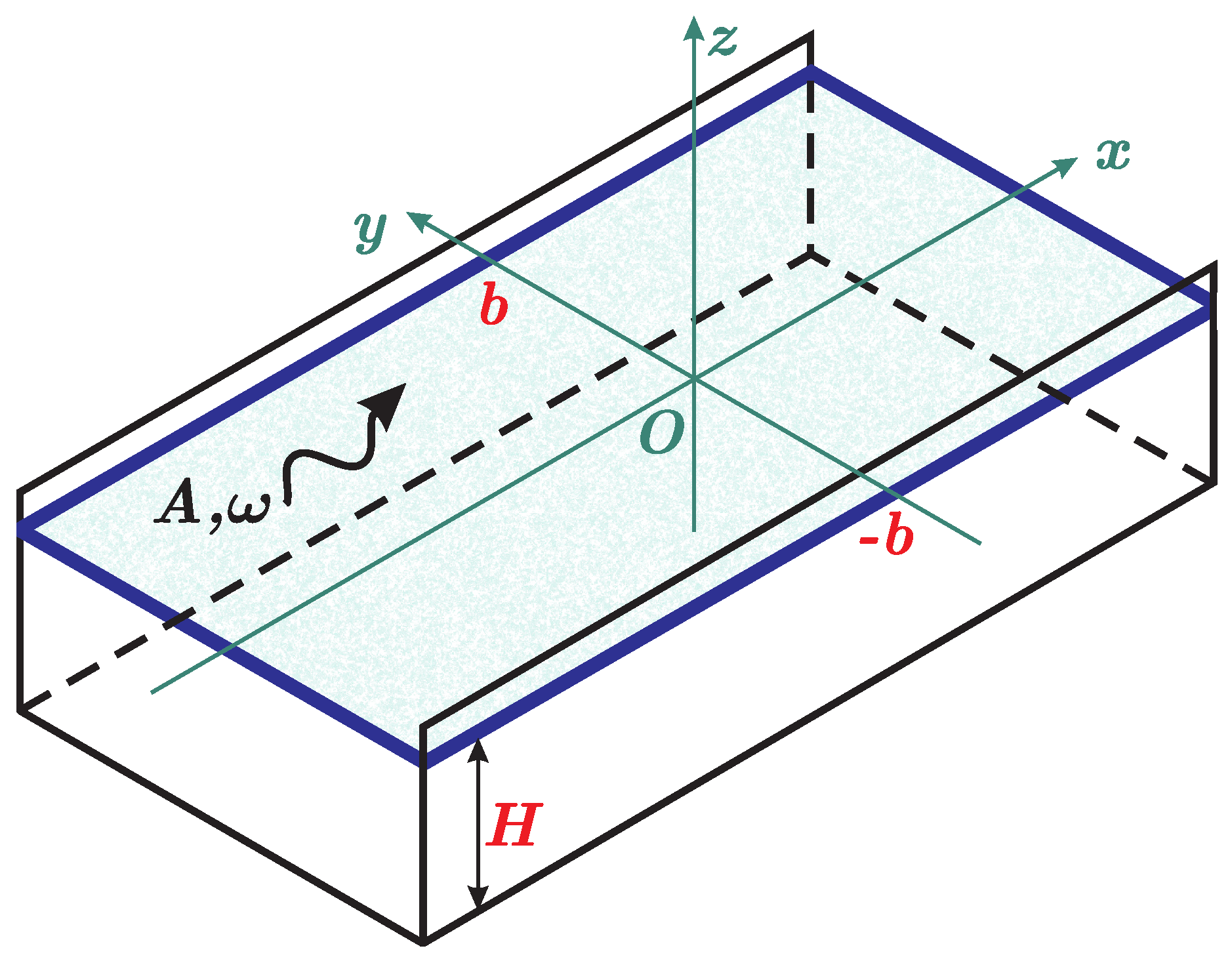
The propagation of steady-state hydroelastic waves in an ice cover channel of infinite extent is considered. Ice is compressed. The channel is of rectangular cross-section with width and depth H. The scheme of the problem and the coordinate axes directions are shown in Figure 1. The liquid in the channel is homogeneous, ideal and incompressible with density . The ice cover is of constant thickness and density . The ice cover is modelled by a thin homogeneous Kirchhoff–Love elastic plate. The ice thickness is assumed to be much less than the channel depth, . The edges of the plate are clamped to the walls of the channel. It is assumed that the plate is uniformly compressed by transverse (from the channel walls) and/or longitudinal (along the channel) constant compressive forces.
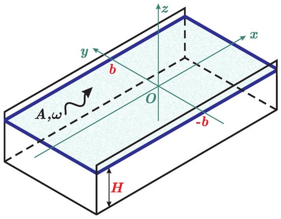
Figure 1.
Scheme of the channel.
The problem is considered within the framework of linear hydroelastic wave theory. It is assumed that flexural-gravity waves with frequency propagate along the ice-covered channel. The maximum of the ice plate deflection is taken as the wave amplitude, A. The liquid flow is assumed to be potential. The liquid velocity and the ice deflection are small. The lower surface of the ice plate is always in contact with the liquid.
The motion of the median ice plate surface, , under compression and hydrodynamic loads is described by the linear plate equation [52],
with clamped boundary conditions along the channel sides,
Here, , where E, , , is the Young’s modulus, thickness, density and Poisson’s ratio of the elastic plate. and are the longitudinal and transverse stress, ( corresponds to compression and to stretching in x and y directions); is the water density, g is the acceleration due to gravity and is the hydrodynamic pressure determined by the linearized Bernoulli equation:
The fluid flow is described by velocity potential , which satisfies Laplace’s equation
and boundary conditions
Furthermore, dimensionless variables are used with the notation being preserved. The length scale is taken as half of the channel width, b, the ratio is the time scale, the amplitude, A, is the scale of ice cover displacements, is the scale of velocity potential. The dimensionless depth of the channel is denoted as h (), and the dimensions of the channel cross-section are .
Solutions to problem (6), (2), (4), (5) are sought in the form of a waves propagating along the channel,
where is a dimensionless wave number (, k is the dimension wave number), then the dimensional length of the wave is .
The hydroelastic waves (7) in a channel are described by the function , the so-called waveform, which is the amplitude function of the plate deflection. Due to the linearity of the problem under consideration, the normalisation condition on the function is chosen as ,
Substitution (7) in (6) lead us to the equation
where the primes stand for derivatives with respect to y. Then, the boundary conditions of (2) are
Therefore, the problem under investigation is formulated as follows: for the known inertia-elastic characteristics of the ice cover and channel parameters, describe the influence of longitudinal and transverse compression of the ice on the hydroelastic waveform , their corresponding dispersion relations, phase and group velocities, as well as deformations and stresses in the ice cover.
3. Solution to the Problem by Normal Modes Method
The solution to the problem is constructed using the method of normal modes, which was described, for example, in [44]. In this method, the deflection of the plate is presented in the form of a series,
where coefficients are to be defined and functions are solutions of the spectral problem,
with orthonormality conditions
The analytical solution to this problem is given in [44]. The functions are either even or odd, which allows us to divide the solution to the problem into two independent parts. The function is found in the form of
where the functions are solutions of the problems
In turn, the functions are defined by separation of variables using the dependence on the transverse coordinate y in the form of even/odd Fourier series, according to the functions.
After substituting (11) and (13) into the Equation (10), multiplying by and integrating by , taking into account (12), we obtain a homogeneous system of linear algebraic equations for the =coefficients ,
where all matrices are symmetric,
The coefficients of matrices and are obtained by analytical formulae in [44] (Formulas (20)–(29)).
The second term in square brackets is due to the compression of the ice cover across the channel and along the channel . A nontrivial solution to the obtained system of linear Equation (14) exists only when the determinant of the matrix is zero. It depends on the parameter . There is a countable set of such values of , and hence of frequencies , for each value of ; see [44,45]. This leads to the set of dispersion curves for hydroelastic waves . To each frequency corresponds the vector (14), which specifies the shape of the oscillations with this frequency in the decomposition of (11). The components of are normalised so that the absolute maximum value of the function is equal to one. The physical characteristics of the ice cover and channel dimensions are included in the coefficients of all matrices and parameters , .
Strains in the Ice Cover
Since ice is a rather brittle material, the stress values leading to ice plate failure are reached before the plate deformations go beyond the linear theory for small amplitude waves. In the linear theory of the plate, the stresses are proportional to the strain and vary linearly through the ice thickness and are zero at the middle of the plate thickness. At any location, the maximum strain is achieved at the surface of the ice plate.
The solution to the problem is sought in the form of waves propagating along the channel (7), so it is a periodic function with respect to phase ,
The absolute maximum of strain in the plate is a function of the dimensionless parameters and can be calculated by the formula
where
The scale of the strains is taken as .
The strains field in the ice plate is described in terms of the strain tensor [44], which is given by the form
where is a non-dimensional variable across the ice thickness, . To evaluate the maximum strain at the point of the ice sheet, we need to identify the principal strain and find its absolute maximum. The principal strain, , can be found through the eigenvalues of the strain tensor, , by the formula
where
As mentioned above, in the framework of linear theory the maximum strains are reached at the ice surface, at . The functions (17) are smooth functions on the variable , so the maximum of (16) is reached at one of their extremum points and are determined from the condition
The maximum principal strain modules along the wavelength are determined from the solution of Equation (18) as (see [47])
where
Note that, in fact
and corresponds to the maximum transverse or longitudinal strains with respect to the channel axis. The value corresponds to maximum strains that are neither longitudinal nor transverse and form a non-zero angle with the channel axis.
4. Numerical Results
Calculations of linear hydroelastic waves in the channel are performed for freshwater ice with density , Young’s modulus and Poisson’s ratio . The thickness of the ice cover is m, the channel width is m and the channel depth is m. The results of calculations for waves with lengths greater than 6 m () and periods greater than 0.3 s are presented below. Under these conditions, .
The solution to the algebraic system (14) was constructed by the reduction method. The results of calculations show that the usage of 20 modes, , in the decomposition of the cross-sectional deflection forms (11), is enough to obtain dispersion relations, elastic strain and strain distributions with a high degree of accuracy in the considered ranges of wave numbers, k, and frequencies, .
To determine the dispersion relations relating the frequency of the bending-gravity-tatation wave, , and the wave number, k, we calculated the values at fixed , for which the determinant of the system matrix (14) turned to zero. Then, for each root of this algebraic equation, the dependences for the corresponding form were determined. Note that the dispersion relations are obtained separately for even and odd forms of . The two first forms of each type were considered. The following numeration by form is then used: the first form, , is the first even form, the second form, , is the first odd form, the third form, , is the second even form and the fourth form, , is the second odd form. The same numeration is applied to the dispersion relations for each form.
It is convenient to introduce compression parameters , , similarly as it was done in [57].
Three separate cases of plate compression are considered. The first of them is for longitudinal compression, along the channel, with , , the second one is for transverse compression, from the channel walls with , and the third one is for uniform compression with .
4.1. Compression along the Channel (Longitudinal Compression)
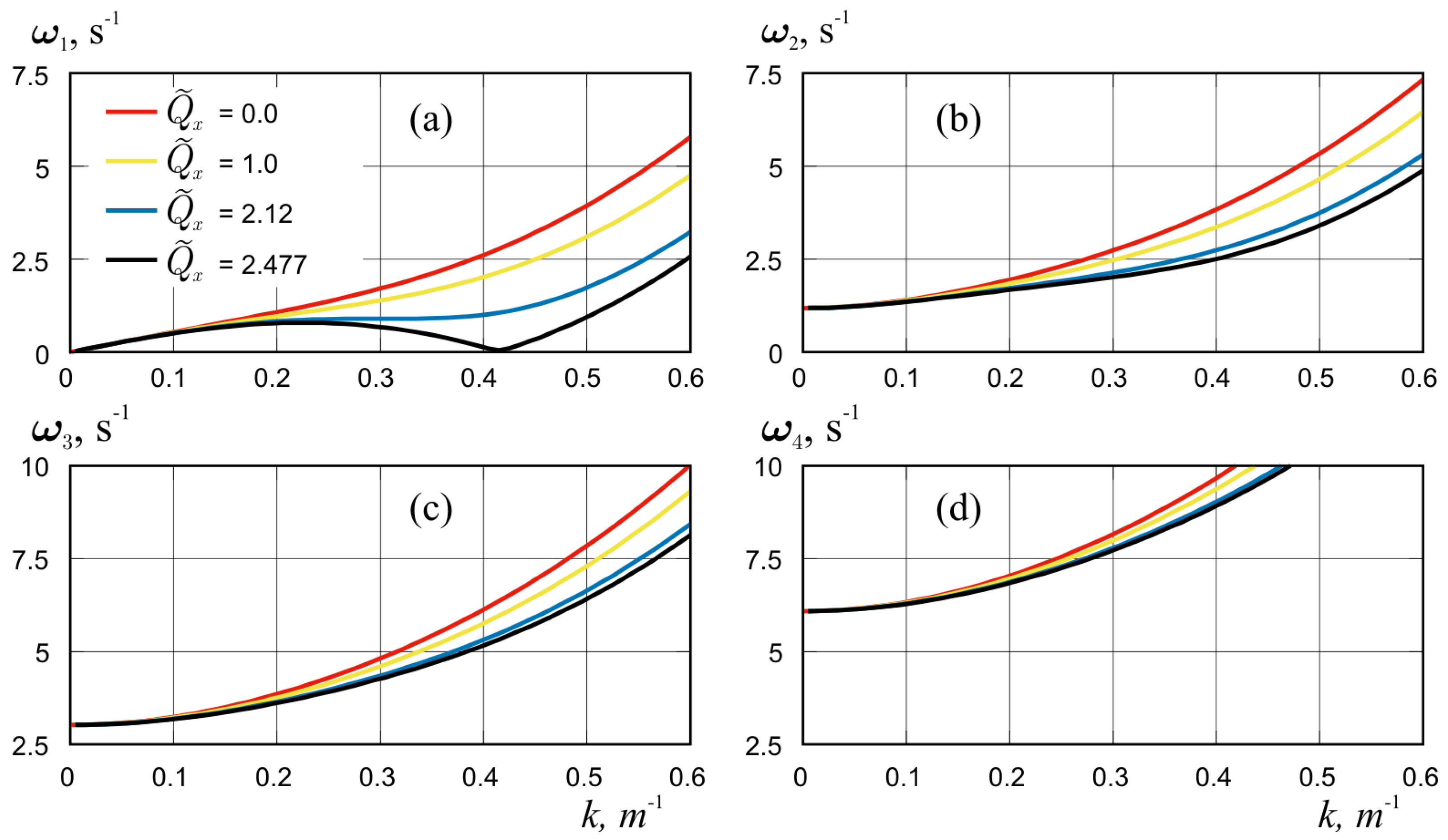
In this subsection, the influence of increasing at on parameters of flexural-gravity waves is investigated. As in the case of waves in the ice cover of a channel without ice compression [44], the dispersion relation for each k has a countable set of solutions. Each branch of the solution represents a wave of a certain form across the channel, with its own dispersion curve. Figure 2 shows the dispersion relations, , for the four first forms, , of hydroelastic vibrations of ice at four different values of longitudinal compression, . The red lines for the case without compression are the same as in [44]. It is easy to see that, for any value of compression considered here, the curves with number n are lower than the curves with number , as it was in [44]. Figure 2 demonstrates that as compression increases, the frequencies of all forms become smaller for shorter wavelengths, while for long wavelengths (small k) the frequency values do not change significantly and have the same limit as in the absence of compression.
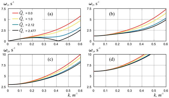
Figure 2.
Dispersion curves in the case of longitudinal compression for four values, , and for the first four waveforms, , n = 1–4, plots (a–d), correspondingly.
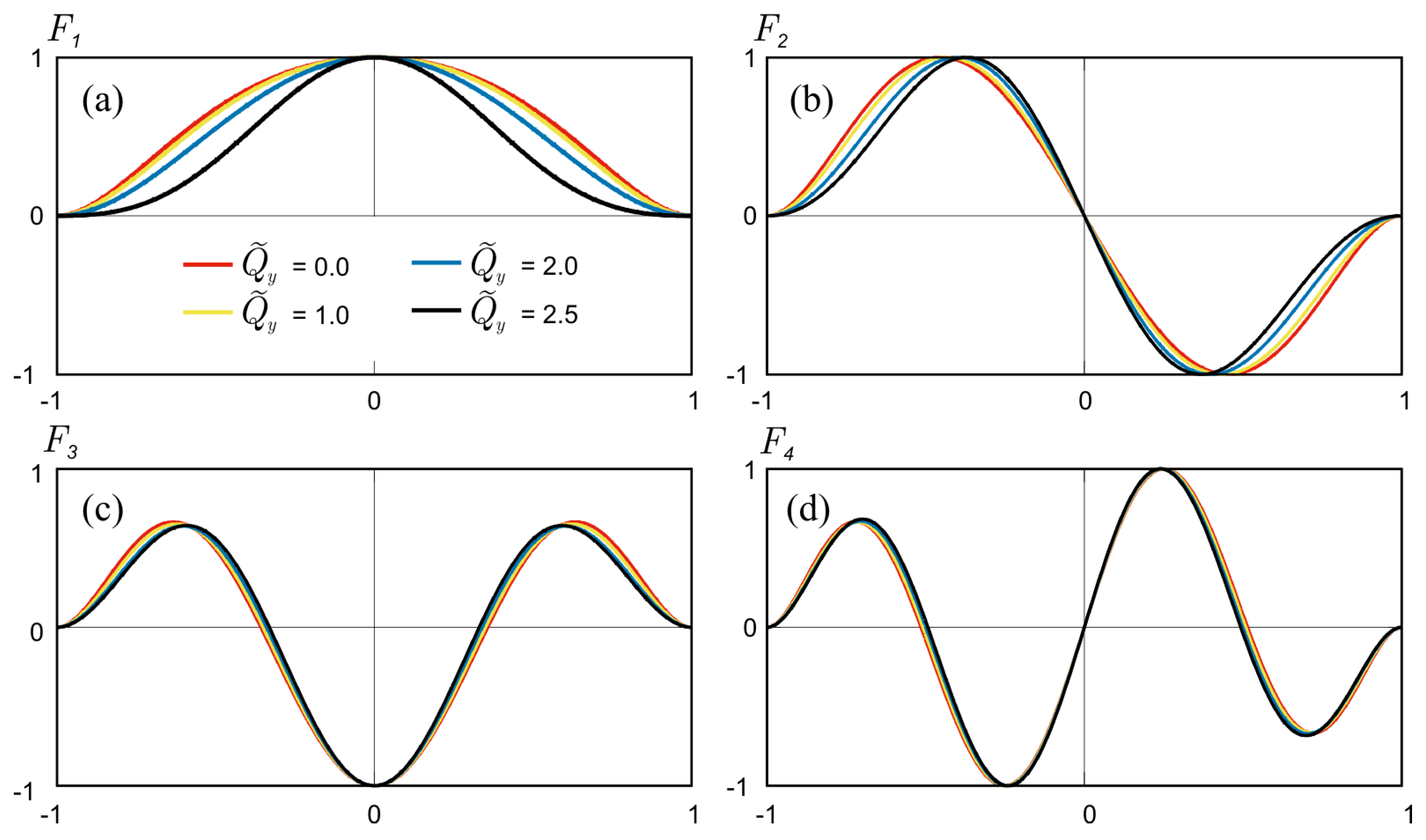
Figure 3 compares the forms of oscillations across the channel under two conditions: without compression and with compression (). The case without compression is referenced in Figure 7 [44]. In both cases, the wave number and the data have been normalized so that the highest value is 1. For this particular case of longitudinal compression, no significant changes in the form of the oscillations were observed.

Figure 3.
Deflection of the plate across the channel for even hydroelastic wave forms , (a) and odd waveforms , (b) without longitudinal compression (solid lines) and with compression (dashed lines) in dimensionless variables.
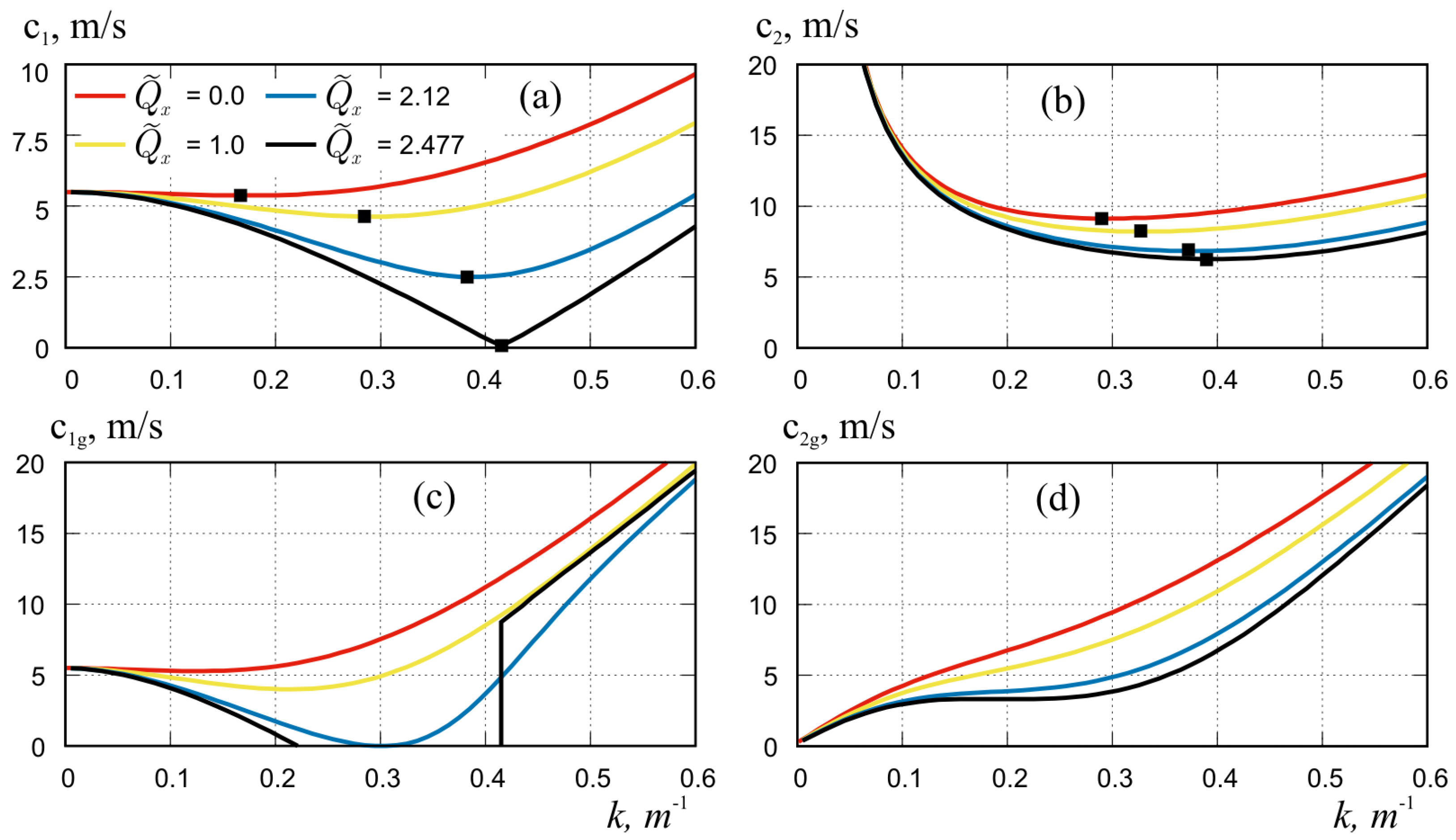
The behaviour of the dispersion curves, , for the first waveform, , in Figure 2a is of special interest. It corresponds to the behaviour of dispersion curves for unbounded ice (see, for example, [57,60]). At small compression , the dispersion curves increase and their derivative of k is positive. This case corresponds to the normal behaviour of the dispersion curves. At the value (blue curve), an inflection point of the curve appears on it , which is defined as the threshold of “blocking”. At that point, the group velocity, , and its derivative of k turn to zero (see Figure 4c).
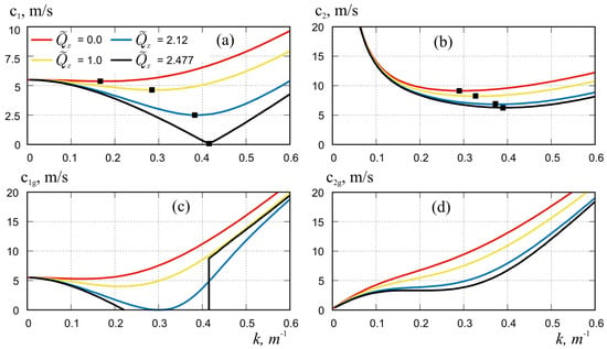
Figure 4.
Phase velocities (a,b) and group velocities (c,d) for the first (a,c) and second (b,d) waveforms in longitudinal compression, for . Symbols show the critical velocities.
With further increase of compression, for a non-monotonic behaviour of the dispersion curve, indicating anomalous dispersion with the existence of three waves of different wave numbers and the same frequency. At on the dispersion curve there is a specific point with wave number , when the frequency turn to zero, than phase velocity also turn to zero and no oscillations with this wave number exist. In the paper by Kerr [52], the value of compressible force for which phase velocity becomes zero was indicate as the “buckling limit” of the floating structure. It is also specified by Kheysin [4] as “static force which causes the loss of stability of the ice plate”. These critical values of the longitudinal compression of the channel ice cover along which the hydroelastic wave propagates are slightly higher than the corresponding values for the unbounded plate ( and 2, respectively; see [4,7]), which can be explained by the influence of clamped boundary conditions on the channel walls. Further increases of compression lead to an interval of wave numbers for which there are no hydroelastic waves with positive frequencies. According to Kheysin [4], such regimes are called “unstable regimes”. Note that this effect exist for the first form of hydroelastic waves only and does not occur for other waveforms; see Figure 2b–d.
The phase and group velocities for the first and second hydroelastic waveforms at longitudinal compression for are shown in Figure 4. It can be seen that with increasing compression, all velocities of both waveforms decrease. We found similar behaviour for higher modes as well. For the long waves, at the velocities are almost independent of compression. For medium wavelengths, at , the effect of compression on the velocity change is the strongest and increases with increasing k. For short waves, at compression also leads to a decrease in velocities, but the relative difference in values for compressed and uncompressed plates is smaller than for medium-length waves.
The dependence of group and phase velocities changes most significantly for the first waveform. For them, at maximum compression, , the critical velocity (minimum phase velocity) goes to zero at (Figure 4a). For the group velocity, at a slightly lower compression, , also reaches zero for the first waveform with and becomes negative for the whole range of k when the compression is further increased (Figure 4c), which indicates the abnormal behaviour of this curves. The group and phase velocities for the first waveform on Figure 4a,c, their minima and discontinuities are consistent with the specific behaviour of the dispersion curves for this waveform on Figure 2a.
The phase velocity minima, marked in Figure 4a,b, indicate the critical velocities of flexural-gravity wave propagation for the corresponding forms and values of compression. For these values of k, the group and phase velocities are equal and waves propagate without radiating energy. Therefore, when the load moves with a velocity equal to the critical velocity, the amplitude of deflections for the system without dispersion increases to infinity, and in the presence of dispersion the amplitudes of deflections and stresses in the floating plate have well pronounced maxima (see [48,49,50,51]). Since the dispersion curves for the first waveform at large compression have abnormal behaviour, we can indicate the critical velocities only if . A detailed analysis of such a phenomenon is given, for example, in [60].
4.2. Compression across the Channel (Transverse Compression)
In this subsection, we consider the case of transverse compression from the channel walls with , . This compression can arise, for example, due to the expansion of the ice volume when the channel freezes.
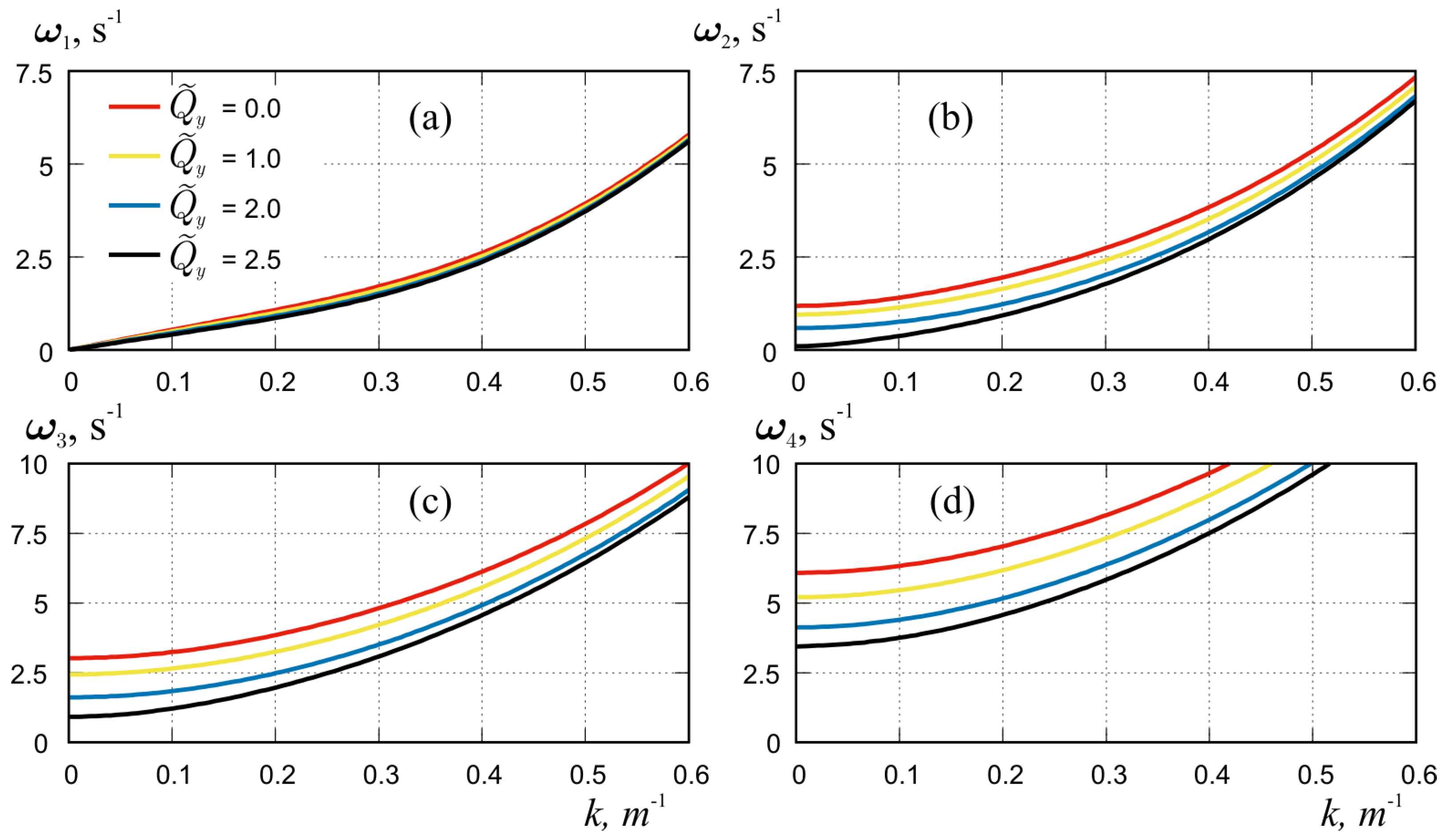
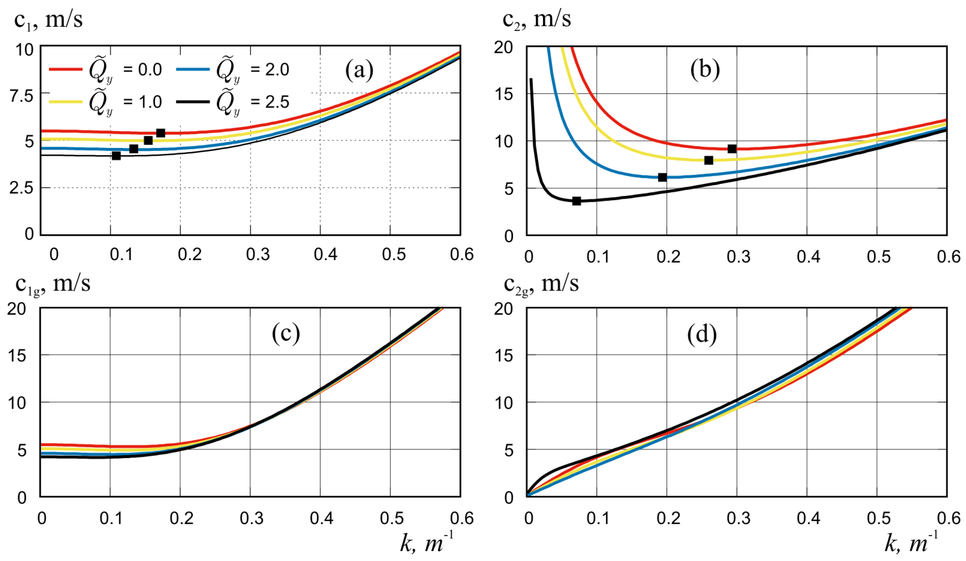
Figure 5 shows the dispersion relations, , for four first forms of hydroelastic oscillations of ice at different values of transverse compression, . As in the case of longitudinal compression, in this case there is a reduction of frequencies for all forms with increasing compression. It is weakest for the first form. However, for the other forms a significant decrease of frequencies with increasing compression can be observed. However, unlike in the case of longitudinal compression, the frequencies of all forms become significantly smaller for the long wavelength (small values of wave numbers k).
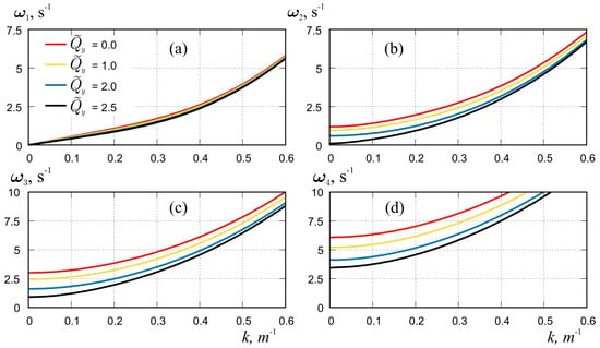
Figure 5.
Dispersion curves, , in the case of transverse compression for four values, , and for first four forms, , n = 1–4, plots (a–d), correspondingly.
In Figure 6a, the dispersion curves for the first and second forms of compressed waves are plotted on an enlarged scale for . It can be seen that the frequency values for the second form on a short interval, , are smaller than for the first form, . Thus, at transverse compression, waves of the first form can propagate along the ice cover of the channel with the same or higher frequency as waves of the second form. This is different from their usual behaviour in the absence of compression or in the case of compression.

Figure 6.
Dispersion curves (a) and phase velocities (b) in the case of transverse compression for first and second waveforms at .
Figure 7 shows the amplitudes of oscillation across the channel for the first four hydroelastic waves, , under transverse compression of the ice cover, , at wave number .
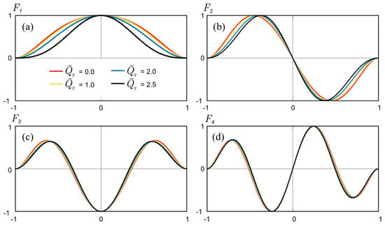
Figure 7.
Deflection of the plate across the channel for hydroelastic waveforms , n = 1–4, plots (a–d), correspondingly, under transverse compression, for in dimensionless variables.
It can be seen that with increasing transverse compression, the curvature of forms near the clamped edges of the plate decreases, and near the peaks it increases. These changes are mainly observed for the first two forms, , and . The other forms are little affected by compression. Calculations have shown that with increasing wave number, k, the influence of compression becomes even less. As noted above, longitudinal compression of the ice cover has practically no effect on the forms of ice cover oscillations.
In Figure 8, the phase and group velocities for the first and second forms of hydroelastic waveforms at transverse compression for are shown. For this case, the phase velocities of the waves of both waveforms also decrease with increasing compression (Figure 8a,b). This effect is especially strong for the second form. Moreover, the phase velocity of the second form in the interval , for compression , is smaller than that of the first one (see Figure 6b for details). Thus, at such transverse compression, waves of the first form can propagate along the ice cover of the channel faster than waves of the second form, which differs from their usual behaviour without compression. Note that the critical velocities (phase velocity minima) for the first waveform change slightly during transverse compression of ice, whereas for the second form the changes in critical velocities are significant. The group velocities for transverse compression (Figure 8c,d) are slightly different from the group velocities in the uncompressed case, unlike that for longitudinal compression (see Figure 4c,d).
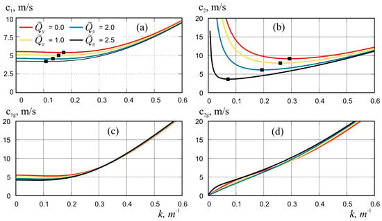
Figure 8.
Phase velocities (a,b) and group velocities (c,d) for the first (a,c) and second (b,d) waveforms in transverse compression, for . Symbols show the critical velocities.
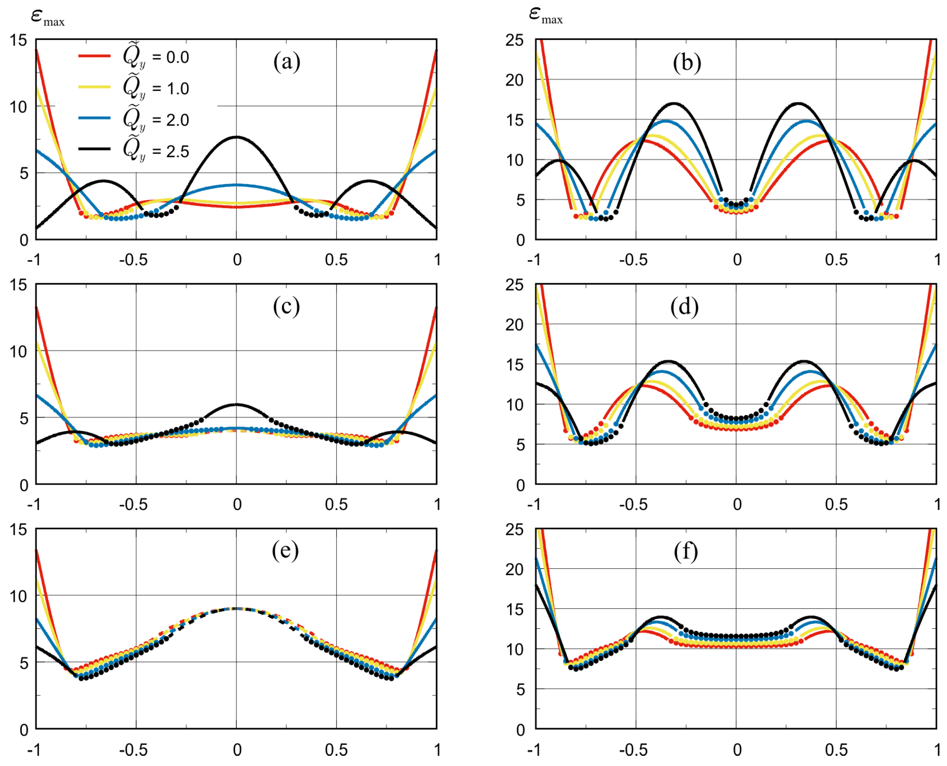
Figure 9 shows the distributions of the dimensionless strains (see (16)) for the hydroelastic waves of the first two waveforms, and (see Figure 7a,b), with wave numbers under transverse compression . The reason for choosing these values of the calculation parameters is due to the fact that the compression forces have the greatest influence on the shape of waveforms in transverse compression, especially for the first and second forms (see Figure 3 and Figure 7). In addition, the forces of transverse compression have a particularly strong effect on frequencies for long wavelengths (small k) (see Figure 5). The performed calculations have shown that for other forms and wave numbers, k, the strain distributions for compressed ice are not significantly different from the uncompressed ice case.
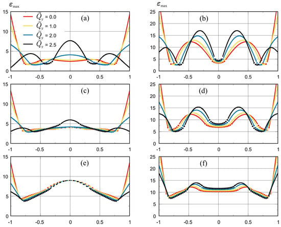
Figure 9.
The scaled distributions of strain maximum in ice cover across the channel, , for transverse compression , for the first form (a,c,e) and second form (b,d,f) of hydroelastic waves, (a,b), (c,d), (e,f). Solid lines are for transverse strains, dashed lines for longitudinal, markers for combined strains.
The solid parts of the curves on Figure 9 correspond to transverse strains, , dashed lines are for longitudinal strains, , dotted lines are for combined strains, . With the channel dimensions and ice thickness used in the calculations, the scale of strains is .
It can be seen that the maximum strain along the dimensionless channel width for both forms at uncompressed ice, , are achieved at the edges of the ice cover, , and correspond to transverse strains. With increasing compression, , the strains at the edges decrease but increase inside the channel. At , there is a sharp change in the strains distribution pattern; specifically, the maximum strains are reached inside the channel, at the points of local extrema of the forms and (see Figure 7a,b). For small and , these internal maxima correspond to transverse strains (Figure 9a–d). As k increases, the internal maxima at some values start to correspond to longitudinal strains. For the first form it will be at (Figure 9e), for the second form at . Then, as well as for uncompressed ice, as k increases the internal longitudinal strain in the ice cover increases rapidly, exceeding the transverse strain at the edges. Note that the combined strains (dotted lines) do not become absolutely maximum in any of the graphs.
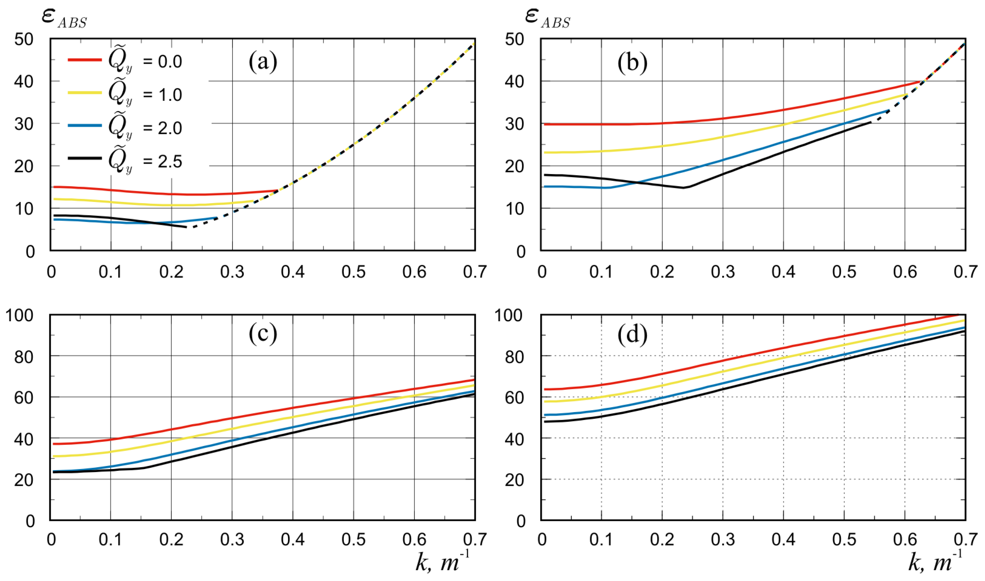
Figure 10 shows the distributions of the absolute strain maxima, (15), in the ice sheet as functions of the wave number, k, of the first four forms of hydroelastic waves at different values of transverse compression, . The solid parts of the curves correspond to transverse strains, , dashed lines are for longitudinal strains, . It can be seen that with increasing transverse compression all absolute strains decrease, which corresponds to the well-known fact that an elastic plate becomes stiffer under compression. At small compression, , all curves are similar to those for uncompressed ice, ; specifically, at small k there are parts of the curves where the absolute maximum strains are transverse and are reached at the edges of the plate (solid lines). For the first and second waveforms, Figure 10a,b, as k increases all curves join into one common curve corresponding to longitudinal strains inside the plate (dashed line). For strong compression, , at small values of wave number k, special regions corresponding to transverse elongations inside the plate at the points of waveforms extrema are observed on the curves, Figure 10a,b. However, as k increases the curves tend to return to the normal regime with a maximum of transverse elongations at the edges followed by a maximum of longitudinal strains inside the plate. The absolute maxima for the higher forms, Figure 10c,d, decrease monotonically with increasing compression, without any special behaviour at small k.
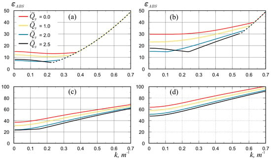
Figure 10.
The scaled absolute strain maxima, , in the ice sheet as functions of the wave number k of the first four forms of hydroelastic waves (a–d) for transverse compression, . Solid lines are for transverse strains, dashed lines are for longitudinal strains.
In investigating the maximum stresses, one should keep in mind the yield strength of the material, generally defined as the strain, , at which the material begins to deform plastically. It is required that the strain in the ice sheet is below the yield strain, , of ice, to prevent our elastic model from being unrealistic. In this study, we take an estimate of (see [19]) and limit the wave amplitude, A, for given and for the first mode is then . When transverse compression is increased, the strain, , is reduced, Figure 10a, so a large wave amplitude is allowed, which does not lead to ice plastic deformations and breakup.
4.3. Compression with Longitudinal and Transverse Components
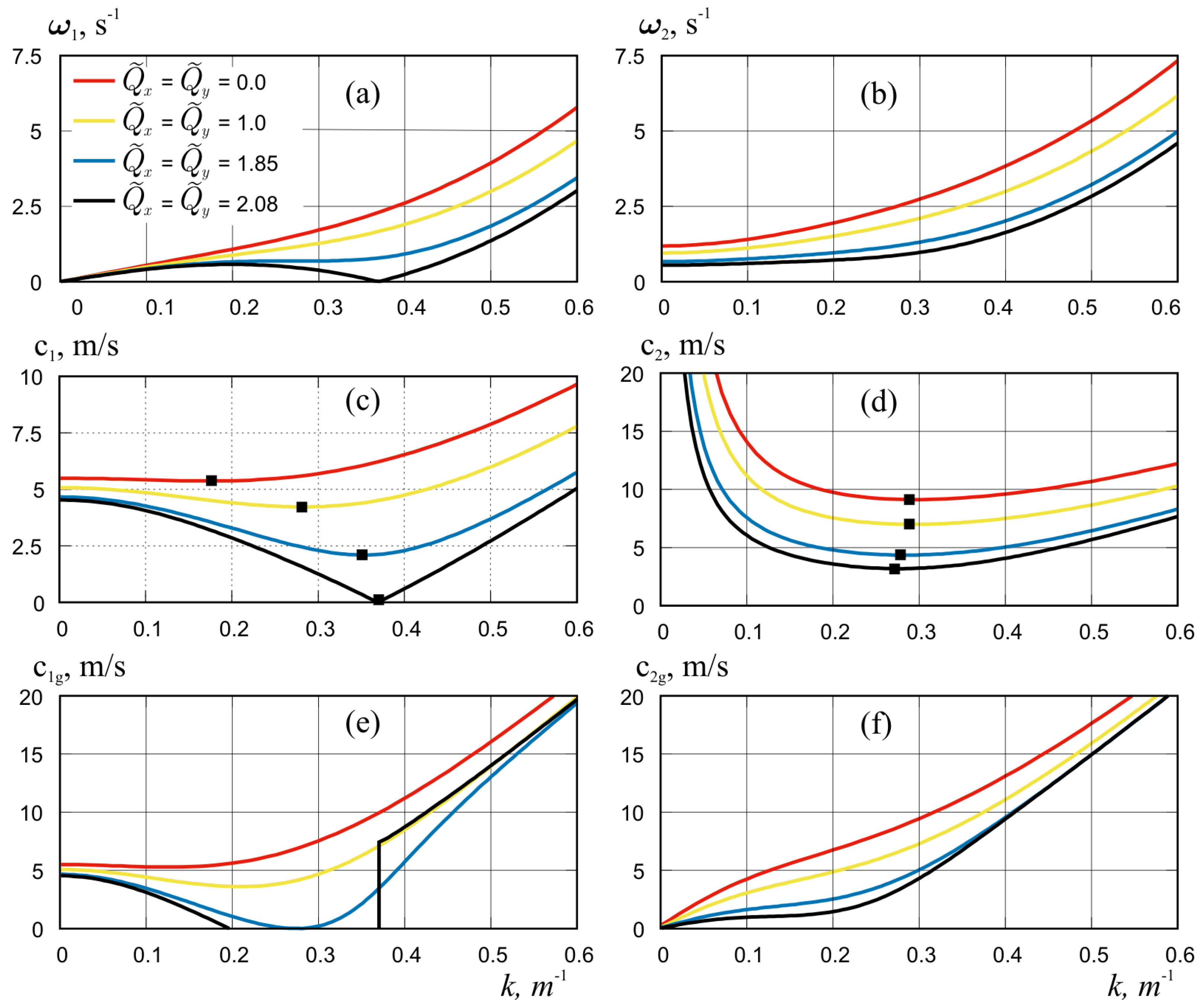
To investigate the effect of ice cover compression on hydroelastic wave propagation, modelling calculations were performed for the case of identical longitudinal and transverse compression. Figure 11 shows the results of calculating the dispersion curves, phase and group velocities for the first two waveforms, because they are the most sensitive to ice compression.
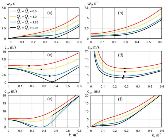
Figure 11.
Dispersion curves (a,b), phase velocities (c,d) and group velocities (e,f) for the first (a,c,e) and second (b,d,f) waveforms in homogeneous longitudinal and transverse compression, for . Symbols show the critical velocities.
It can be seen that for the first waveform the strongest influence on the hydroelastic characteristics is caused by the longitudinal compression of the ice, because the behaviour of all the curves shown in Figure 11a,c,e generally repeats similar results for the case of longitudinal compression only (Figure 2a and Figure 4a,c). However, the longitudinal compression forces corresponding to the “blocking” phenomenon and “buckling limit” have slightly lower values in the presence of transverse compression than in its absence: vs. and vs. . The influence of transverse compression has a stronger effect on the characteristics of the second form, Figure 11b,d,f, especially for long wavelengths at small values of wave number k.
5. Conclusions
The present study is concerned with the propagation of flexural-gravity waves in ice channels. The main attention was paid to the effect of ice compression forces on the propagating wave parameters, namely, on the dispersion relations of these hydroelastic waves, their form, phase and the critical velocities, as well as on the strain in the plate. Three cases were investigated: compression in the longitudinal or transverse direction and uniform compression. The problem was solved in the framework of the linear theory of hydroelasticity. The solution to the considered problem is obtained in the form of a series of the vibration modes of an elastic beam without compression. The obtained system of algebraic equations for the mode decomposition coefficients was solved numerically.
It was shown that the compression forces and their direction significantly affect the propagation of flexural-gravity waves. In all considered cases, the dispersion curves showing the value of frequencies as a function of wave number decrease with increasing compression. However, specific features are found in each case. Thus, at compression along the channel the main effect is related to the propagation of the first waveform. Abnormal behaviour of the dispersion curves, as well as “buckling” and “blocking” phenomenon, previously obtained for waves in unbounded ice [4,52] and described in more detail in later work, (see, for example, [57,60]), have been observed. In this case, the “buckling limit” and the magnitude of compression at the point where the “blocking phenomenon” appears became higher due to the increased stiffness of the ice cover caused by the clamped conditions at the channel walls. At the same time, the forms of propagating waves themselves remained practically unchanged. The dispersion curves for all forms for long waves also did not change, but they decreased for short waves. The abnormal behaviour of the dispersion curves caused a decrease in the group and hence in the critical velocities.
For the case of transverse compression, abnormal behaviour of the dispersion curves was not detected. The dispersion curves for all forms decreased not only for short waves but also for long waves. In particular, this leads to the fact that at strong compression the values of frequencies and phase velocities for the second form became slightly lower than for the first form. That is, waves of the first form can propagate through the ice cover of the channel with the same or higher frequency and velocity than waves of the second form.
In the case of uniform compression, the main effects are obtained and seen to be the similar to compression along the channel. That is, the dispersion curves for the first mode are close to those in the case of longitudinal compression, but the “buckling limit” and the magnitude of compression at the point where the “blocking phenomenon” occurs are slightly lowered and approached the values for unbounded ice. At the same time, transverse compression affected the curves for the higher forms.
The greatest influence of compression forces on the strain distribution was observed in transverse compression, especially for the first and second waveforms and long waves. It is shown that for very long waves the maximum strains are achieved at the channel walls at low compression, and they correspond to transversal strains, i.e., cracks in the ice can form along the channel walls. With decreasing wavelength and increasing compression, the maxima move to the centre of the channel and correspond to longitudinal strains, i.e., cracks in the ice can form across the channel. It was observed that the combined strains did not become absolutely maximal in any of the cases considered.
The results of the study show that the force of compression and compression direction both have a major effect on the propagation of the first two forms of waves, on both the shape and speed of propagation and on the strain distribution within the ice plate.
Author Contributions
Conceptualization, T.K. and E.B.; methodology, T.K. and E.B.; software, E.B.; validation, E.B.; formal analysis, T.K. and E.B.; investigation, T.K. and E.B.; resources, T.K. and E.B.; writing—original draft preparation, T.K. and E.B.; writing—review and editing, T.K. and E.B.; visualization, E.B. All authors have read and agreed to the published version of the manuscript.
Funding
This study was supported by RFBR and TUBITAK according to the research project 20-58-46009 “Loads on engineering structures in sea ice”.
Data Availability Statement
Data of numerical calculations are available upon request.
Conflicts of Interest
The authors declare no conflicts of interest.
References
- Aksenov, Y.; Popova, E.E.; Yool, A.; Nurser, A.J.G.; Williams, T.D.; Bertino, L.; Bergh, J. On the future navigability of Arctic sea routes: High-resolution projections of the Arctic Ocean and sea ice. Mar. Policy 2017, 75, 300–317. [Google Scholar] [CrossRef]
- Greenhill, A.G. Wave motion in hydrodynamics. Am. J. Math. 1886, 9, 62–96. [Google Scholar] [CrossRef]
- Kheysin, D.Y. Moving load on an elastic plate which floats on the surface of an ideal fluid. Izv. Akad. Nauk SSSR Otd. Tekh. Nauk Mekh. i Mashinostr. 1963, 1, 178–180. (In Russian) [Google Scholar]
- Kheysin, D.Y. Dinamika ledyanogo pokrova (Dynamics of Floating Ice Covers). In Leningrad: Gidrometeorologicheskoe Izdatel’stvo; Technical Translation FSTC-HT-23-485-69; US Army Foreign Science and Technology Center: Charlottesville, VA, USA, 1967. [Google Scholar]
- Nevel, D.E. Moving Loads on a Floating Ice Sheet; No. CRREL-RR-261; US Army Cold Regions Research and Engineering Lab.: Hanover, NH, USA, 1970. [Google Scholar]
- Squire, V.A.; Hosking, R.; Kerr, A.; Langhorne, P.J. Moving Loads on Ice Plates; Kluwer: Dordrecht, The Netherlands, 1996. [Google Scholar]
- Schulkes, R.M.S.M.; Hosking, R.J.; Sneyd, A.D. Waves due to a steadily moving source on a floating ice plate. Part 2. J. Fluid Mech. 1987, 180, 297–318. [Google Scholar] [CrossRef]
- Hosking, R.J.; Sneyd, A.D.; Waugh, D.W. Viscoelastic response of a floating ice plate to a steadily moving load. J. Fluid Mech. 1988, 196, 409–430. [Google Scholar] [CrossRef]
- Squire, V.A.; Robinson, W.H.; Langhorne, P.J.; Haskell, T.G. Vehicles and aircraft on floating ice. Nature 1988, 333, 159–161. [Google Scholar] [CrossRef]
- Hinchey, M.; Colbourne, B. Research on low and high speed hovercraft icebreaking. Can. J. Civ. Eng. 1995, 22, 32–42. [Google Scholar] [CrossRef]
- Zhestkaya, V.D. Numerical solution of the problem of an ice sheet under a moving load. J. Appl. Mech. Tech. Phys. 1999, 40, 770–775. [Google Scholar] [CrossRef]
- Yeung, R.W.; Kim, J.W. Effects of a translating load on a floating plate—Structural drag and plate deformation. Fluids Struct. 2000, 14, 993–1011. [Google Scholar] [CrossRef]
- Kashiwagi, M. Transient responses of a VLFS during landing and take-off of an airplane. J. Mar. Sci. Technol. 2004, 9, 14–23. [Google Scholar] [CrossRef]
- Pogorelova, A.V. Wave Resistance of an Air-Cushion Vehicle in Unsteady Motion over an Ice Sheet. J. Appl. Mech. Tech. Phys. 2008, 49, 71–79. [Google Scholar] [CrossRef]
- Meylan, M.H.; Sturova, I.V. Time-dependent motion of a two-dimensional floating elastic plate. J. Fluids Struct. 2009, 25, 445–460. [Google Scholar] [CrossRef]
- Pogorelova, A.V.; Kozin, V.M.; Matyushina, A.A. Stress-strain state of ice cover during aircraft takeoff and landing. J. Appl. Mech. Tech. Phys. 2015, 56, 920–926. [Google Scholar] [CrossRef]
- Tkacheva, L.A. Behavior of a semi-infinite ice cover under a uniformly moving load. J. Appl. Mech. Tech. Phys. 2018, 59, 258–272. [Google Scholar] [CrossRef]
- Johnsen, K.; Kalisch, H.; Părău, E.I. Ship wave patterns on floating ice sheets. Sci. Rep. 2022, 12, 18931. [Google Scholar] [CrossRef]
- Brocklehurst, P.; Korobkin, A.A.; Pǎrǎu, E.I. Interaction of hydro-elastic waves with a vertical wall. J. Eng. Math. 2010, 68, 215–231. [Google Scholar] [CrossRef]
- Brocklehurst, P.; Korobkin, A.; Pǎrǎu, E.I. Hydroelastic Wave Diffraction by a Vertical Cylinder. Philos. Trans. R. Soc. A 2011, 369, 2832–2851. [Google Scholar] [CrossRef] [PubMed]
- Bhattacharjee, J.; Guedes Soares, C. Flexural Gravity Wave over a Floating Ice Sheet near a Vertical Wall. J. Eng. Math. 2012, 75, 29–48. [Google Scholar] [CrossRef]
- Korobkin, A.A.; Malenica, S.; Khabakhpasheva, T. Interaction of Flexural-Gravity Waves in Ice Cover with Vertical Walls. Philos. Trans. R. Soc. A. 2018, 376, 20170347. [Google Scholar] [CrossRef]
- Ren, K.; Wu, G.X.; Ji, C.Y. Diffraction of Hydroelastic Waves by Multiple Vertical Circular Cylinders. J. Eng. Math. 2018, 113, 45–64. [Google Scholar] [CrossRef]
- Tkacheva, L.A. Oscillations of a Cylinder beneath an Ice Cover in the Neighborhood of a Vertical Wall. Fluid Dyn. 2020, 55, 300–313. [Google Scholar] [CrossRef]
- Disibuyuk, N.B.; Yilmaz, O.; Korobkin, A.A.; Khabakhpasheva, T.I. An Iterative Method for Interaction of Hydro-Elastic Waves with Several Vertical Cylinders of Circular Cross-Sections. J. Mar. Sci. Eng. 2022, 10, 723. [Google Scholar] [CrossRef]
- Evans, D.V.; Porter, R. Wave scattering by narrow cracks in ice sheets floating on water of finite depth. J. Fluid Mech. 2003, 484, 143165. [Google Scholar] [CrossRef]
- Porter, D.; Evans, D. Diffraction of flexural waves by finite straight cracks in an elastic sheet over water. J. Fluids Struct. 2007, 23, 309–327. [Google Scholar] [CrossRef]
- Tkacheva, L.A. Wave motion in an ice sheet with crack under uniformly moving Load. Fluid Dyn. 2019, 54, 14–32. [Google Scholar] [CrossRef]
- Barman, S.C.; Das, S.; Sahoo, T.; Meylan, M.H. Scattering of flexural-gravity waves by a crack in a floating ice sheet due to mode conversion during blocking. J. Fluid Mech. 2021, 916, A11. [Google Scholar] [CrossRef]
- Wang, R.; Shen, H.H. Gravity waves propagating into an ice-covered ocean: A viscoelastic model. J. Geophys. Res. Oceans 2010, 115. [Google Scholar] [CrossRef]
- Meylan, M.; Bennetts, L.; Peter, M. Water-wave scattering and energy dissipation by a floating porous elastic plate in three dimensions. Wave Motion 2017, 70, 240–250. [Google Scholar] [CrossRef]
- Chen, H.; Gilbert, R.P.; Guyenne, P. Dispersion and attenuation in a porous viscoelastic model for gravity waves on an ice-covered ocean. Eur. J. Mech.-B/Fluids 2019, 78, 88–105. [Google Scholar] [CrossRef]
- Zavyalova, K.N.; Shishmarev, K.A.; Korobkin, A.A. The response of a poroelastic ice plate to an external pressure. J. Sib. Fed. Univ. Math. Phys. 2021, 14, 87–97. [Google Scholar] [CrossRef]
- Wu, Q.Y.; Khabakhpasheva, T.I.; Ni, B.Y.; Korobkin, A.A. Small-amplitude waves in a floating poroelastic plate forcing by vertical pitching plate. Phys. Fluids 2023, 35, 117127. [Google Scholar] [CrossRef]
- Pǎrǎu, E.I.; Dias, F. Nonlinear effects in the response of a floating ice plate to a moving load. J. Fluid Mech. 2002, 460, 281–305. [Google Scholar] [CrossRef]
- Marchenko, A. Nonlinear Phenomena in Resonant Excitation of Flexural–Gravity Waves. J. Ship Ocean Technol. Soc. Nav. Archit. Korea 2003, 7, 1–12. [Google Scholar]
- Plotnikov, P.I.; Toland, J.F. Modelling nonlinear hydroelastic waves. Philos. Trans. R. Soc. Lond. A Math. Phys. Eng. Sci. 2011, 369, 2942–2956. [Google Scholar] [CrossRef] [PubMed]
- Dinvay, E.; Kalisch, H.; Părău, E.I. Fully dispersive models for moving loads on ice sheets. J. Fluid Mech. 2019, 876, 122–149. [Google Scholar] [CrossRef]
- Ni, B.Y.; Khabakhpasheva, T.I.; Semenov, Y.A. Nonlinear gravity waves in the channel covered by broken ice. Phys. Fluids 2023, 35, 102118. [Google Scholar] [CrossRef]
- Van der Sanden, J.J.; Short, N.H. Radar satellites measure ice cover displacements induced by moving vehicles. Cold Reg. Sci. Technol. 2017, 133, 56–62. [Google Scholar] [CrossRef]
- Kozin, V.M.; Pogorelova, A.V. Wave resistance of amphibian aircushion vehicles during motion on ice fields. J. Appl. Mech. Tech. Phys. 2003, 44, 193–197. [Google Scholar] [CrossRef]
- Zhestkaya, V.D.; Kozin, V.M. Ice Breaking with Air-Cushion Vessels Using a Resonant Method; Dal’nauka: Vladivostok, Russia, 2003; 160p. (In Russian) [Google Scholar]
- Kozin, V.M. The Resonant Method of Ice Breaking: Inventions and Experiments; Academy of Natural Sciences: Moscow, Russia, 2007. (In Russian) [Google Scholar]
- Korobkin, A.A.; Khabakhpasheva, T.I.; Papin, A.A. Waves propagating along a channel with ice cover. Eur. J. Mech.-B/Fluids 2014, 47, 166–175. [Google Scholar] [CrossRef]
- Batyaev, E.A.; Khabakhpasheva, T.I. Hydroelastic waves in a channel covered with a free ice sheet. Fluid Dyn. 2015, 50, 775–788. [Google Scholar] [CrossRef]
- Ren, K.; Wu, G.X.; Li, Z.F. Hydroelastic waves propagating in an ice-covered channel. J. Fluid Mech. 2020, 886, A18. [Google Scholar] [CrossRef]
- Shishmarev, K.; Zavyalova, K.; Batyaev, E.; Khabakhpasheva, T. Hydroelastic waves in a frozen channel with non-uniform thickness of ice. Water 2022, 14, 281. [Google Scholar] [CrossRef]
- Shishmarev, K.A.; Khabakhpasheva, T.I.; Korobkin, A.A. The response of ice cover to a load moving along a frozen channel. Appl. Ocean Res. 2016, 59, 313–326. [Google Scholar] [CrossRef]
- Shishmarev, K.A.; Khabakhpasheva, T.I.; Korobkin, A.A. Ice response to an underwater body moving in a frozen channel. Appl. Ocean Res. 2019, 91, 101877. [Google Scholar] [CrossRef]
- Zeng, L.D.; Korobkin, A.A.; Ni, B.Y.; Xue, Y.Z. Moving load in an ice channel with a crack. Appl. Ocean Res. 2022, 121, 103086. [Google Scholar] [CrossRef]
- Khabakhpasheva, T.I.; Shishmarev, K.A.; Korobkin, A.A. Large-time response of ice cover to a load moving along a frozen channel. Appl. Ocean Res. 2019, 86, 154–165. [Google Scholar] [CrossRef]
- Kerr, D. The critical velocities of a load moving on a floating ice plate that is subjected to in-plane forces. Cold Reg. Sci. Technol. 1983, 6, 267–274. [Google Scholar] [CrossRef]
- Bukatov, A.E. Influence of a longitudinally compressed elastic plate on the non-stationary wave motion of a homogeneous liquid. Fluid Dyn. 1980, 15, 687–693. [Google Scholar] [CrossRef]
- Bukatov, A.E.; Zharkov, V.V.; Zav’yalov, D.D. Three-dimensional bent-gravity waves with non-uniform compression. J. Appl. Mech. Tech. Phys. 1991, 32, 867–872. [Google Scholar] [CrossRef]
- Eyov, E.; Klar, A.; Kadri, U.; Stiassnie, M. Progressive waves in a compressible-ocean with an elastic bottom. Wave Motion 2013, 50, 929–939. [Google Scholar] [CrossRef]
- Il’ichev, A.T. Solitary wave packets beneath a compressed ice cover. Fluid Dyn. 2016, 51, 327–337. [Google Scholar] [CrossRef]
- Stepanyants, Y.; Sturova, I. Waves on a compressed floating ice plate caused by motion of a dipole in water. J. Fluid Mech. 2021, 907, A7. [Google Scholar] [CrossRef]
- Stepanyants, Y.; Sturova, I. Hydrodynamic Forces Exerting on an Oscillating Cylinder under Translational Motion in Water Covered by Compressed Ice. Water 2021, 13, 822. [Google Scholar] [CrossRef]
- Sturova, I.V. Motion of a load over an ice sheet with non-uniform compression. Fluid Dyn. 2021, 56, 503–512. [Google Scholar] [CrossRef]
- Das, S.; Sahoo, T.; Meylan, M.H. Dynamics of flexural gravity waves: From sea ice to Hawking radiation and analogue gravity. Proc. R. Soc. A 2018, 474, 20170223. [Google Scholar] [CrossRef]
Disclaimer/Publisher’s Note: The statements, opinions and data contained in all publications are solely those of the individual author(s) and contributor(s) and not of MDPI and/or the editor(s). MDPI and/or the editor(s) disclaim responsibility for any injury to people or property resulting from any ideas, methods, instructions or products referred to in the content. |
© 2024 by the authors. Licensee MDPI, Basel, Switzerland. This article is an open access article distributed under the terms and conditions of the Creative Commons Attribution (CC BY) license (https://creativecommons.org/licenses/by/4.0/).

