Article

Dynamic Response of PCCP under the Rockfall Impact Based on the Continuous–Discontinuous Method: A Case Study

1
Institute of Water Resources and Hydro-Electric Engineering, Xi’an University of Technology, Xi’an 710048, China
2
Northwest Engineering Corporation Limited, Xi’an 710048, China
*
Author to whom correspondence should be addressed.
Water 2024, 16(6), 801; https://doi.org/10.3390/w16060801
Submission received: 17 February 2024 / Revised: 2 March 2024 / Accepted: 5 March 2024 / Published: 7 March 2024

Abstract

:
Rockfalls are major geological hazards threatening prestressed concrete cylinder pipes (PCCPs) in water diversion projects. To accurately assess the impact of large deformation movements of rockfalls on PCCPs, this study utilized the continuous–discontinuous method to investigate the dynamic response of a PCCP under a rockfall. The impact mode of rockfalls, the mechanical characteristics of PCCP, and the nonlinear-contact characteristics between soil and PCCP were considered in this study. The advantages of continuous and discontinuous numerical simulation methods were utilized to establish a continuous and discontinuous coupling model of “tube-soil-rock” considering the interaction of soil and structure. The impact mechanism and process of PCCP under the rockfall were investigated by simulating the rockfall process and analyzing its spatiotemporal evolution. The influence of PCCP under rockfalls with different heights and radii was studied to clarify the effects of these two parameters on the PCCP. Combined with a practical application example of large-scale water transfer projects, there is a tendency of center flattening under static load and dynamic impact load, and the PCCP part directly below the impact point is the most dangerous. This investigation provided a comprehensive understanding of the impact mechanism of the PCCPs under rockfall. The findings of this study have significant implications for the design of the protection engineering of PCCPs and ensuring the safe operation of water diversion projects.

1. Introduction

China possesses abundant water resources. However, the distribution of water resources still has the characteristics of uneven spatial and temporal distribution, i.e., more in the south and less in the north, as well as large inter-annual variation, which exacerbates water shortages. Water scarcity is a critical constraint on economic development and social well-being in arid and semi-arid regions. Consequently, a series of ambitious water transfer projects have been launched, including the Central Yunnan Water Transfer Project, the Yangtze–Huaihe River Diversion Project, and the Han–Huaihe River Diversion Project. To ensure the success of these projects, selecting materials for long-distance water transmission pipelines is crucial to their safe and efficient operation. Commonly used materials include steel pipes, concrete pipes, and prestressed steel cylinder concrete pipes (PCCPs). Among these materials, the PCCP is a new composite pipe made of a steel cylinder, prestressing wire, a concrete core, and a mortar coating. The PCCP boasts an ideal combination of the tensile strength and impermeability of steel pipes with the superior compression and corrosion resistance of concrete pipes [1,2,3], and is the preferred choice for large-diameter transmission pipelines for long-term projects at high working pressures and high soil cover, as well as municipal, industrial, and agricultural water supply and drainage works. Due to the long distance of pipeline burial and the diverse geological units in water diversion projects, especially in western China, the main battlefield of the Belt and Road Initiative, pipelines face harsh natural environments such as complex terrain, active tectonic movements, and frequent mountain hazards [4,5]. Among them, rockfalls are one of the typical disasters that causes pipeline damage and failure. Therefore, analyzing and researching the dynamic response of PCCPs under rockfall impacts will greatly enhance the protection and overall safe operation of long-distance water transfer projects, which has significance for scientific research and value for engineering practice.
In recent years, numerous domestic scholars have utilized various numerical simulation methods to explore the safety characteristics of PCCPs. A finite element calculation model was established by Yu et al. [6] to investigate the interaction between a PCCP and its foundation. They analyzed the stress distribution of the pipe body under different water pressures during backfilling. A new wire-wrapping model was proposed by Xiong et al. [7] which uses the nonlinear finite element method (FEM) to simulate the wire-wrapping prestress process of embedded prestressed concrete tubes. They replaced the resultant stress, which was obtained by another FEM and affected by tensile stress in the prestressing wire, with the equivalent radial pressure around the pipe. The equivalent load method was utilized by Gomez et al. [8] to replace the wire prestress, and failure criteria were proposed to evaluate a PCCP through finite element simulation of prestress loss analysis. Advanced numerical modeling by nonlinear finite elements was used to model the effect of the number and location of broken wire wraps on the structural performance of PCCPs by Hajali et al. [9]. The full interaction between adjacent pipes with harnessed joints, as well as combined internal and external loading with full soil–pipe interaction, were considered in this model. Additionally, the reinforcement effect of the lining structure on PCCPs for different numbers of broken wires was simulated by Ge and Sinha [10]. In order to address the issue of rockfalls’ impacts on the safe operation of prestressed concrete cylinder pipes (PCCPs), a “rock-soil-pipe” model for buried PCCP subjected was established by Mao et al. [11] for spherical rockfall impact by employing the finite element theory. The process of rockfall impact on buried PCCPs was simulated, and the stress and plastic strain patterns of the pipeline under various rockfall impact loads were analyzed. Such research holds great significance for comprehending the operational behavior of PCCPs. However, most studies have focused on static load analysis, and few have investigated the dynamic response of PCCPs under impact loads, such as rockfalls. This lack of investigation makes it difficult to meet the requirements for the protection of long-distance water diversion projects.
In studies involving rockfall impacting pipelines, most theoretical analysis methods [12,13,14] simplify the dynamic problem of buried pipelines under impact load as a static problem, which is inconsistent with the actual situation of impact load of a single pulse type. The test methods of rockfall impact [15,16] usually have the problems of heavy workload, high cost, and long duration, resulting in less relevant test research. In the realm of numerical simulation, numerous scholars have explored the dynamic response process of buried pipelines under the vertical impact of rockfalls through the FEM. They have also analyzed the influence of rockfall parameters (impact velocity, radius, eccentric distance), pipeline parameters (internal pressure, wall thickness, diameter, buried depth), and location on the pipeline. For instance, Zhang et al. used numerical simulation methods to investigate the buckling behavior of pipelines under the impact of square [17] and spherical [18] rockfalls, and explored the influence of pipeline and rockfall parameters on the stress and plastic strain of buried pipelines. A three-dimensional finite element model of a buried pipeline under the impact of a rockfall was established by Xiong et al. [19], and the effects of the rockfall’s scale, suspended height, and falling point on pipeline safety were studied. The response of buried steel pipes under impact loading was simulated by Tavakoli Mehrjardi and Karimi [20] based on tests, and a series of parameter analyses were conducted to evaluate the influences of factors such as buried pipe depth, falling point height, impact zone radius, and soil damping. Leine et al. [21] studied the effect of rock geometry on rockfall dynamics through two well-chosen numerical simulations and found that rock shape had a crucial influence on rockfall dynamics. The behavior of a natural gas pipeline impacted by falling objects was studied by Liu and Yang [22] using numerical modeling. The analysis showed that the maximum pipeline stress decreased with increasing relative stiffness of the pipeline and soil. The dynamic process of the response of buried pipelines impacted by high-speed falling rock was simulated by Deng et al. [23] using the discrete element method (DEM). However, the above numerical simulation research revealed the dynamic response law of buried pipelines under the impact of rockfalls only to a certain extent, while it failed to consider the interaction between rockfalls and soil from the perspective of large deformation. During the impact process of rockfalls and soil, large deformation phenomena such as rockfall disintegration and soil extrusion occur, accompanied by complex mechanical behaviors such as viscosity, hardening, and friction energy dissipation. Thus, traditional continuous numerical simulation methods cannot accurately describe the physical and mechanical processes that change rockfall, soil, and buried pipelines.
As for the continuous–discontinuous numerical simulation method, some relevant scholars have applied it to the study of the load on rock impact tunnel structures and buried pipelines. Huang et al. [24] used the discrete element–finite difference coupling calculation method to study and analyze the dynamic response of the shed cave–wall structure in the study area under the impact of falling rocks of different shapes, sizes, impact velocities, and impact angles. Wang et al. [25] adopted the discrete element–finite difference coupling algorithm, in which the discrete element simulates the sand cushion and the finite difference method simulates the concrete structure of the shed cave, and carried out a numerical simulation study on the dynamic response of the shed cave cushion hit by rolling stone at different angles and speeds, revealing the dynamic response characteristics of the shed cave’s structure. Hou et al. [26] used a discrete and continuous interface coupling numerical model to simulate and analyze the loading process of buried pipelines. They utilized the discrete element method to simulate the soil filling around pipes, and the finite difference element method was used to simulate the buried pipelines and the undisturbed soil foundation. In addition, this method has also been widely used in the study of soil and structure failure processes in the key research areas of shield and tunnel engineering [27,28], slope stability research, and other studies. It is sufficient to show that the continuous–discrete coupling algorithm can be used to study the change law of force and displacement and the failure mechanism processes of key regions or structures from the mesoscale. It can also achieve good results and has good application value. However, in the existing literature, there are few reports on the continuous–discontinuous method for buried pipelines under rockfall impact.
In summary, considering the multilayer material characteristics of PCCP and its complex stress system, continuous numerical simulation methods are used in most existing studies to simulate and analyze PCCP, and there are few studies on the dynamic response of PCCP under rockfall impact loads, making it difficult to meet the protection requirements of long-distance water transfer projects. Therefore, the continuous numerical simulation method was adopted in this study to accurately simulate PCCP prestressed steel wire, a mortar protective layer, a socket steel ring, a steel cylinder, and other structures so as to consider the interactions between and influences on different materials and to accurately analyze the dynamic response of PCCP [29,30]. At the same time, considering the large deformation and discontinuous media problems, such as material slip, swelling, or collapse, that may be caused by rockfall impact [31,32], a discontinuous numerical simulation method suitable for large deformation problems should be selected to fully simulate the discontinuous properties of real soil, so as to provide an effective basis for the protection design of rockfalls and the safe operation of PCCP pipelines.

2. Principle of the Continuous–Discontinuous Coupling Method

2.1. Principles of Discrete Element Method (DEM) and the Contact Model

Numerical simulation methods can be divided into continuous medium methods and discontinuous medium methods. The discontinuous medium methods include the particle discrete element method, block discrete element method, and discontinuous deformation analysis method. The discrete element method is based on the assumption of a discontinuous medium, and can simulate the fracture and separation of solid materials. It shows great superiority in simulating the large deformation, discontinuity, and failure separation of granular materials, and is suitable for studying the mechanical behavior between granular materials [33,34,35].
The DEM describes the force–deformation response between the spheres by defining a contact model and forms aggregates to simulate the macroscopic and microscopic characteristics of the backfill, which can greatly reflect the discontinuous mechanical characteristics of the soil. This is achieved through a dynamic action calculation between elements that brings the system towards equilibrium, as depicted in Figure 1 [36,37]. During this calculation, the DEM updates the motion and rotational state of each particle based on unbalanced contact forces by utilizing Newton’s second law and force–displacement relationship theory. Subsequently, it updates the contact force and moment between elements based on the same theory, repeating the calculation until the unbalanced contact force reaches zero.
Various contact models are available in the context of the DEM, such as the linear contact model, Hertz contact model, and parallel contact model. The linear contact model is particularly suitable for simulating the linear elastic behavior between particles. Considering that the backfill soil is mostly non-cohesive sand material, the linear contact model was used to simulate the material properties of backfill soil. The basic principle is shown in Figure 2. The red dotted rectangle is the contact position of the ball.
The contact force is composed of linear ( F n l + F s l ) and damping parts ( F n d + F s d ). The linear part governs the linear elasticity and friction behavior, while the damping part regulates the viscous behavior. Specifically, the linear spring ( k n k s ), with normal stiffness and shear stiffness, generates the linear contact force. Notably, the linear spring cannot endure tension, whereas the shear force adheres to the Coulomb criterion and friction coefficient ( μ ) to control the slip conditions. The  g s  is defined as the surface clearance, that is, the difference between the contact clearance and the reference clearance. The contact force between particles [38,39] can be calculated as:
F = F n + F s
where  F n = F n l + F n d  and  F s = F s l + F s d  denote the normal and tangential contact force components, respectively.  F n l  and  F n d  represent the linear and damping parts of the normal contact force, while  F s l  and  F s d  denote the linear and damping parts of the tangential contact force. The linear part of the normal contact force ( F n l ) is obtained from the normal displacement  U n  of the particle and the normal stiffness  k n  of the contact point, which can be defined as Equation (2).
F n l = k n U n
The damper generates the damping force, which is directly proportional to the normal and shear critical damping ratios ( β n  and  β s ). The normal contact force ( F n d ), which is one of the components of damping, can be mathematically expressed as:
F n d = 2 β n v n m 1 m 2 m 1 + m 2 k n
where  v n  is the relative normal velocity of two contact bodies.  m 1  and  m 2  represent the masses of two contact particles.
Similarly, the linear ( F s l ) and damping ( F s d ) parts of the tangential contact force share certain similarities with the aforementioned calculation method. Notably, due to the absence of cohesive force between backfill particles, the particles tend to slip when the shear force surpasses their shear strength. Specifically, when  F s > μ F n , the particles slip, and the tangential contact force remains constant at a value of  μ F n .

2.2. Principle of the Continuous–Discontinuous Coupling Method

In general, the discontinuous method requires a large number of particles, and the computational efficiency is low. The continuum analysis method mainly includes the finite element method and the finite difference method. It can accurately and efficiently simulate the physical and mechanical properties of large-scale structures through a limited number of element grids and material constitutive models. However, it cannot reflect the evolution processes of soil contact separation, soil particle rotation, or particle damage, and cannot simulate the large deformation of the structure well [40,41]. Accordingly, a singular approach utilizing either a continuous or discontinuous medium analysis cannot holistically characterize the dynamic response of PCCPs subjected to rockfall impacts. To address this issue, we propose a coupled continuous–discontinuous methodology for the numerical simulation of a PCCP under a rockfall. The backfill above the pipeline constitutes a combination of heterogeneous particles and is prone to fragmentation, dispersion, and other significant deformation patterns following a rockfall. Therefore, in the key area of rockfall-impacted backfill, the DEM is used for fine research, fully considering the discreteness of backfill particles and accurately reflecting the effect of rockfall impact on the contact between backfill particles and pipelines [42,43]. For the prestressed concrete cylinder pipes (PCCPs) and the surrounding bedrock, we utilize the finite difference method (FDM) of continuous medium analysis to simulate their physical and mechanical behavior across a broad spectrum, thereby enhancing the computational efficiency and numerical simulation accuracy. Our proposed continuous–discontinuous coupling method facilitates the calculation of stress and deformation in both the bedrock and PCCPs while also delving into the minutiae of soil particle–pipe interactions on a small scale. By amalgamating these diverse elements, our approach enables a precise analysis of the mechanical response of PCCPs under the impact of rockfalls, aligning closely with established engineering practices.
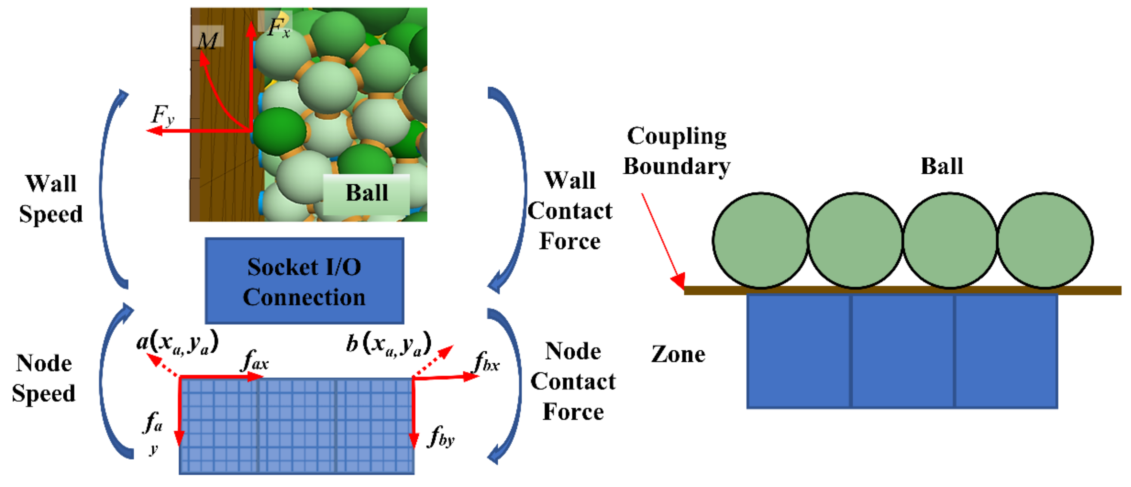
In this research, mechanical analysis of the continuous domain is conducted using the FDM based on the continuous medium analysis method, while mechanical analysis of the discontinuous domain is performed using the DEM based on the discontinuous medium analysis method. The coupling between these two domains occurs at their contact boundary, and the Scoket I/O interface is utilized to transfer calculation data between these domains (refer to Figure 3) [44,45]. During the analysis iteration, the discrete particles in the discontinuous domain produce contact forces and contact bending moments that act on the coupling boundary. These forces are distributed to the vertices of the coupling boundary using the equal force method. As the vertices of the coupling boundary attach to the mesh points of the solid element, the coupling boundary vertices move synchronously with the mesh points of the solid element and participate in the continuous domain analysis. Similarly, the deformation of nodes in the continuous domain also drives the movement of the coupling boundary, which transfers their positions and velocities to the particles in the discontinuous domain via the coupling boundary. These values are constantly updated and recycled to achieve continuous–discontinuous coupling calculations and analyses [46,47].
In Figure 3 x a y a x b , and  y b  are the x and y coordinates of point  a  and point  b , respectively.  F x  and  F y  denote the force components acting on the coupling boundary due to particles in the discontinuous domain, while  M  represents the resultant moment. Additionally, we consider the force components at node a and node b of the continuous domain element, which are denoted by  f a x f a y f b x , and  f b y . The coupling boundary utilizes an equivalent method to distribute the contact force of particles to the vertex force, and the forces on each node are  f a x = β F x f a y = β F y f b x = ( 1 β ) F x , and  f b y = ( 1 β ) F y . We determined the allocation parameter, denoted by β, through Expression (4).
β = M F y x b + F x x b F y ( x a x b ) F x ( y a y b )
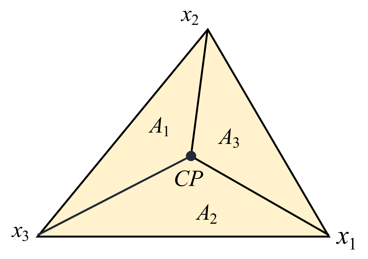
We present the continuous–discontinuous coupling boundary in Figure 4. The triangle represents a coupling boundary consistent with the shape of the solid element. The contact point with particles in the discontinuous region is denoted by  C P , and  C  is located on the coupling boundary corresponding to  C P . Due to the deformation of the contact part, the coupling boundary simultaneously undergoes tensile, shear, and torsional effects, and the positions of  C  and  C P  in space may be inconsistent. The vertex position of the triangle coupling boundary is denoted by  x i ( i = 1 , 2 , 3 ) , and the areas of the three representative triangles are given by  A i r i = C P x i  is defined by the distance between points CP and  x i . Additionally, the total contact force and general bending moment transferred from the contact to the continuous model element are  F  and  M , respectively. The general bending moment  M  can be expressed as:
M = M b + ( C C P ) × F
where  M b  is the bending moment in contact and  ( C C P ) × F  is the bending moment caused by the dislocation of the contact position. During the iteration process, as  F  and  M  are known, the concentrated forces and bending moments exerted on the continuous model elements at corner point  x i  by the contact coupling effect of node  C P  in the discontinuous domain are calculated using a weighted method, according to Expressions (6) and (7).
F i = A i / i = 1 3 A i   F
M i = r i   F i

3. Construction of the “Pipe-Soil-Rock” Continuous–Discontinuous Model

During construction and operation, long-distance buried water pipelines face challenges from harsh natural environments such as complex terrain, active tectonic movements, and a high incidence of mountain disasters. These conditions make pipelines susceptible to various types of engineering disasters, with rockfalls from high places being particularly concerning due to their high kinetic energy [48]. The impact of a rockfall transfers from the backfill to the pipeline, which brings great additional stress; causes pipe pits; adversely affects regular pipeline operation; and can even cause secondary disasters such as leakage and high-pressure water jet flow, posing severe threats to the lives and property of surrounding communities. The Han Wei River Diversion Project in central China is an example of such a water conveyance project. This project encompasses the 98.3 km Qinling water tunnel and a 190.0 km water transmission and distribution network that connects the Yangtze River in southern China to the Yellow River in northern China [49]. This is a major water conservancy construction project intended to achieve a spatial balance of water resource allocation in Shaanxi Province, China. The project is situated in the Qinling Mountains, near the north–south boundary of China, where the terrain and geological conditions are extremely complex; the project faces the threat of complex geological disasters such as rolling stones.
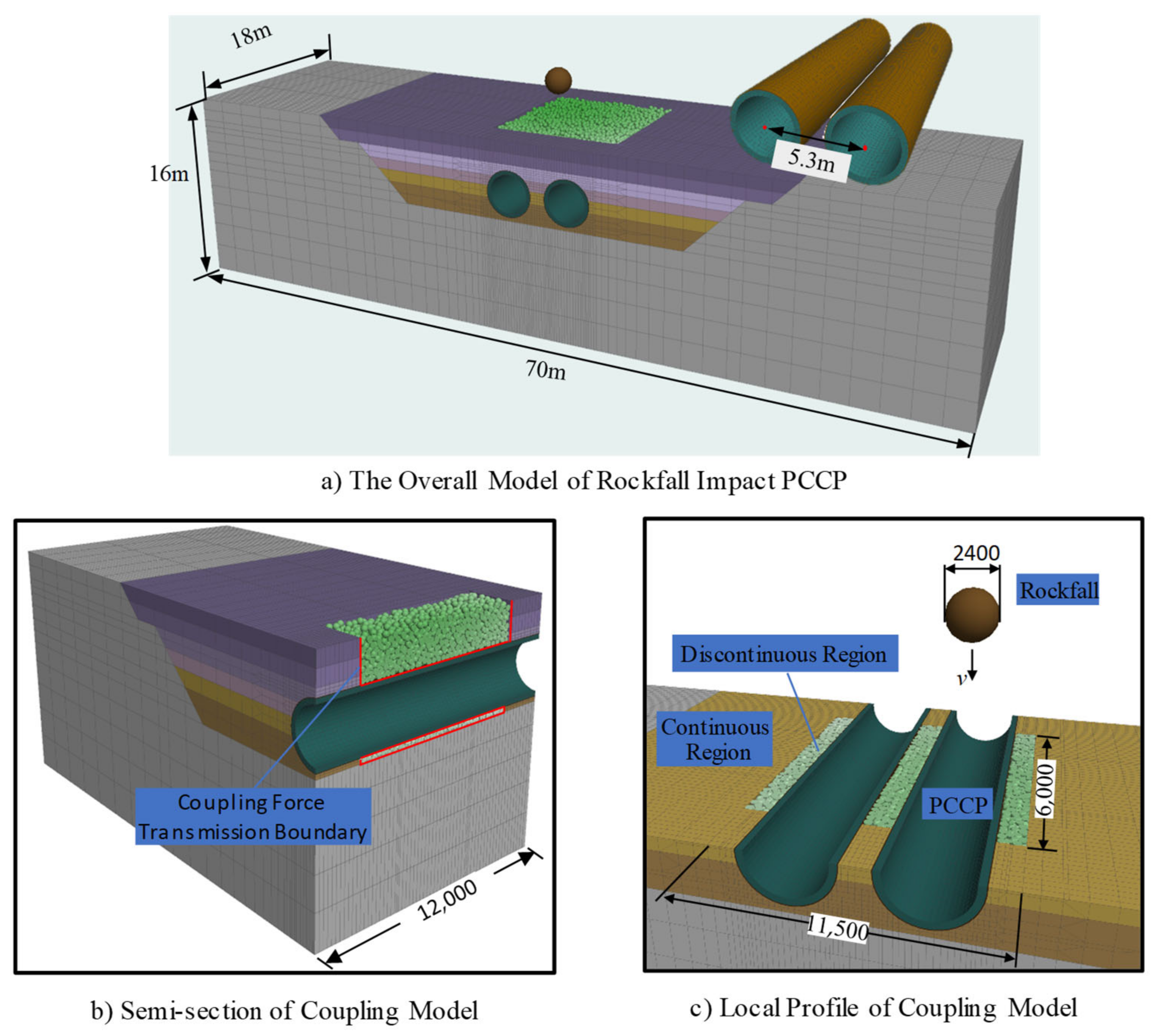
To investigate the dynamic response of a PCCP under the impact of a rockfall, this study used the double line DN3400 PCCP from the upper Huangchi intake tank to the Yangwu watershed of the Han to Wei River Diversion Project as a prototype. The “Pipe-Soil-Rock” model based on the continuous–discontinuous method is constructed in this paper, as shown in Figure 5. The model is introduced as follows: ① The overall model includes three parts: soil, double row PCCP, and rockfall. The soil modeling includes three parts: foundation, cushion, and backfill. ② A continuous simulation is established for the pipeline and surrounding soil, with three pipes (6  ×  3 = 18 m) as the analysis length, an inner diameter of 3.4 m, and a buried depth of 2.5 m. The modeling calculation of the pipeline trench and the 10 m soil around the pipeline trench is carried out [11]. ③ To ensure the accuracy of the simulation, only some backfill areas directly contacting the PCCP are simulated using the DEM, while PCCP and other large-scale foundation soil are simulated using the FDM, as shown in Figure 5b,c. ④ The continuous–discontinuous model is subject to normal constraints around the whole model and fixed constraints at the bottom.

3.1. Construction of the Continuous–Discontinuous Model of the Soil

Considering the simulation of soil fragmentation under rockfall impact, the DEM was utilized to model the cushion and backfill areas surrounding the PCCP, while the FDM was employed to simulate the remaining regions.
(1) Regarding the continuous model of the soil, Figure 5a shows that eight-node hexahedral solid elements were predominantly used to model the different soil segments. The foundation, which was 70 m long, 18 m wide, and 16 m high, was composed of 35,836 elements. The cushion, which was 1.8 m thick, was comprised of 9396 elements, while the backfill had five layers, with a total thickness of 5.9 m and a total of 24,490 units. The thickness of each layer varied, with the numbers of units for each layer as follows: 2732 (0.9 m), 3292 (1.1 m), 8592 (0.9 m), 2488 (1.0 m), and 2488 (1.0 m). The density, elastic modulus, and Poisson’s ratio values of each part of the soil mass are listed in Table 1; they were determined based on geological survey data.
(2) For the discontinuous model of the soil mass, Figure 5c shows that a 6.7 m thick area, including the 11.5 m long and 6 m wide cushion and backfill region around the PCCP, was selected for simulation using the DEM. The randomly distributed [50] particle generation method was used to generate the particles of the cushion and each backfill layer six times. As the calculation began, the particle system diffused and popped open, and the redundant particles in each layer were subsequently deleted after the calculation was balanced. The total number of particles in the simulated soil was 21,610. In terms of the contact model, a linear contact model was used to simulate the properties of the cohesionless sand material in the backfill, while a parallel bond model was employed to prevent bond failure at the coupling boundary during the impact process. The discrete element parameters used in the proposed model were determined based on previous research [51,52,53] results, and are shown in Table 2 and Table 3.

3.2. Construction of the PCCP Continuous Model

In this study, the FDM was utilized to simulate the behavior of a PCCP comprising concrete, a steel cylinder, prestressing wire, and a mortar coating. A segmented modeling approach was utilized to individually characterize the four components, and the PCCP model was based on the FDM, as depicted in Figure 6. The simulation process aimed at enhancing both accuracy and computational efficiency through the following key modifications: ① The prestressing wire was simulated by the independent wire rings using the cable structure element according to the study of Yulong. Three rings of prestressing wire were combined into one ring to improve the calculation efficiency. The diameter of the wire was 10.39 mm (the cross-sectional area was 3 times that of the single-ring prestressing wire), and the spacing of the wires was 37.23 mm. ② For the spigot-and-socket joint position, the influence of the water-stop rubber ring on the structure was ignored, while the role of the steel ring was focused. In this simulation, the steel ring was modeled using shell structure elements. The shell element had a length of 150 mm, with 20 mm and 10 mm thicknesses for the outer and inner layers, respectively. ③ The steel cylinder was attached to the surface of the zone of the inner layer concrete and was simulated using shell structure elements. The inner diameter of the steel cylinder was 3600 mm, and the thickness was 1.5 mm. ④ For the concrete core and mortar coating, the simulation used eight-node hexahedron solid elements, where the numbers of elements in the first and second sections of the PCCP were 2976 and 1008, respectively. The last PCCP modeling step simplified the end socket, and the numbers of material units were 2880 and 960, respectively. The material parameters of the different layers of the PCCP finite difference model are presented in Table 4.

3.3. Construction of the Discontinuous Model of Rockfall and Setting of Calculation Conditions

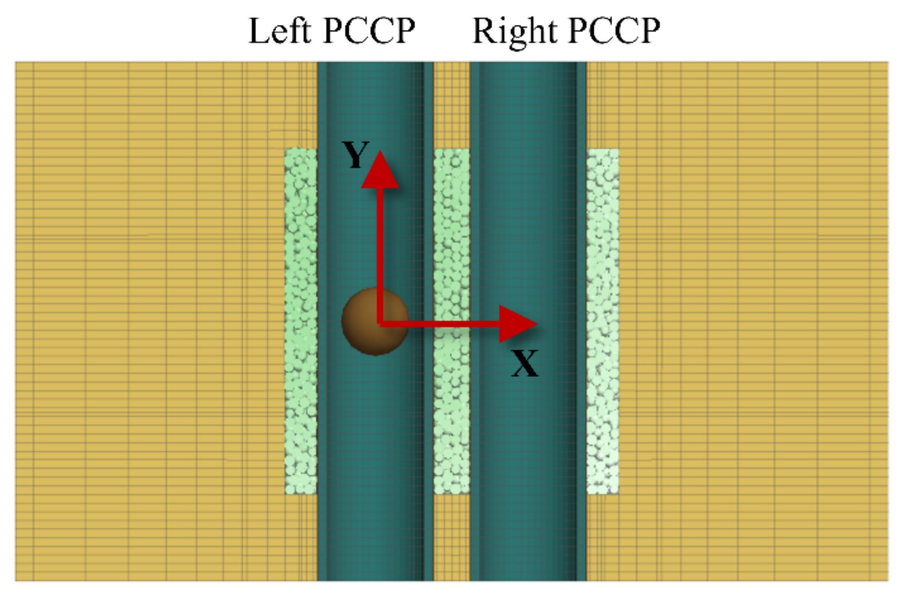
In the continuous–discontinuous model, the construction of a rockfall model of arbitrary shape generally requires the use of more complex wall elements to build a frame, and then requires the sphere to be filled with clump elements, which is more complicated. In this study, a single rigid ball was used to simulate falling rock, taking into account the influence of irregular rock shapes [18,21]. The acceleration due to gravity in the model was set to 9.8 m/s2, and the density of the rockfall was set to 2500 kg/m3. The impact of a rockfall on a PCCP is determined by rockfall parameters such as the rockfall’s radius and height. To investigate the impact mechanism of a rockfall on a PCCP, a coordinate system was established, and a comparison scheme of working conditions was set. The coordinate system was established with the center of the second PCCP on the left as the coordinate origin, the X-direction perpendicular to the pipe axis, and the Y-direction parallel to the pipe axis, as illustrated in Figure 7. According to the existing records on the collapse of water diversion projects, there are landslides and rockfall accidents in the middle, east and west lines of the South-to-North Water diversion project. The heights of the falling rocks are mostly concentrated in the ranges of 10~30 and 6~8 m, and there are also individual occurrences of about 2 m [54,55,56]. A total of 20 working conditions were set using the control variable method to study the influence of different falling radii and falling heights on the PCCP components. The working conditions are outlined in Table 5.

4. Analysis of the Spatial–Temporal Evolution of a PCCP under an Impact Load

4.1. The Simulation Results of the Rockfall Impact Process

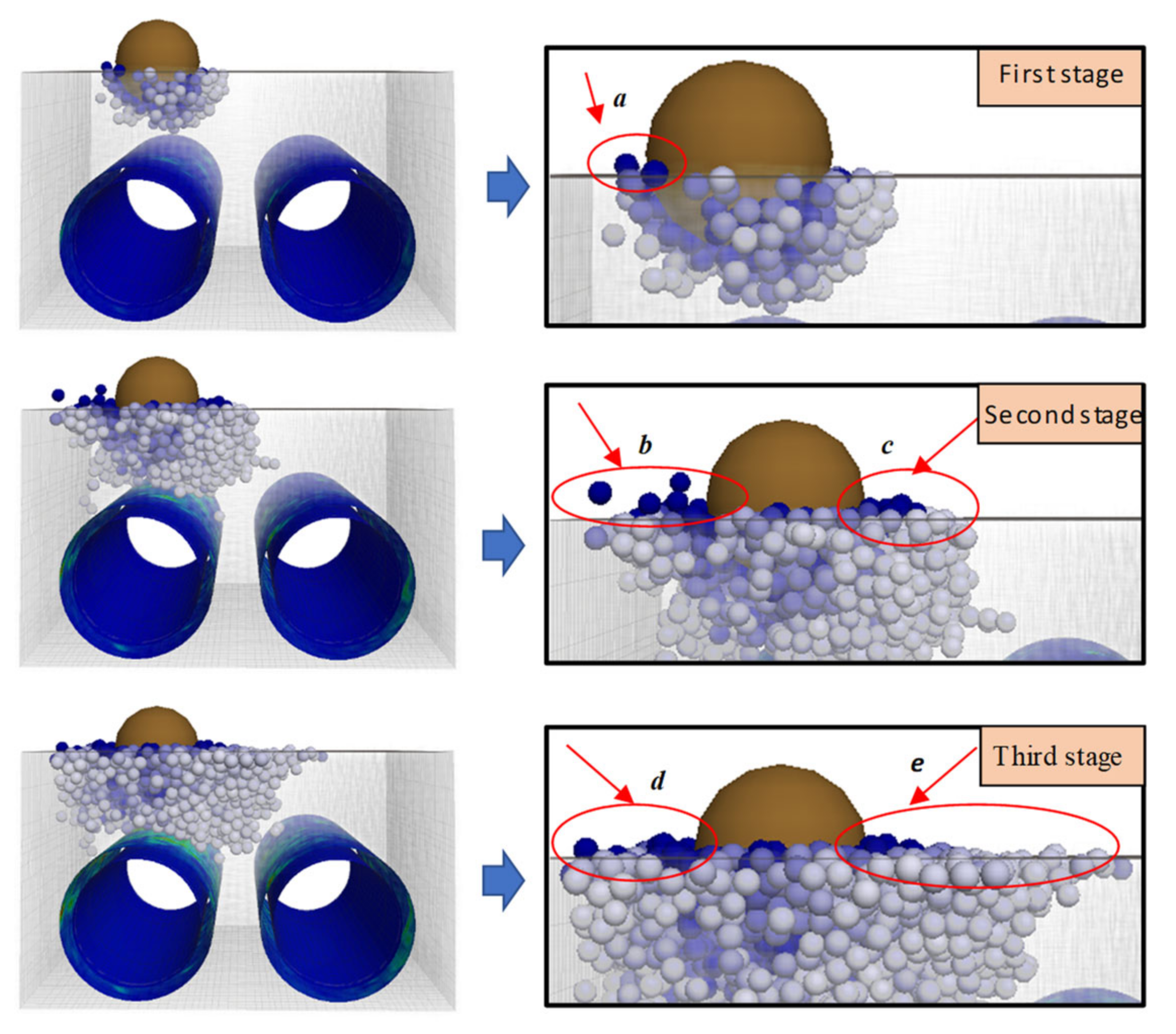
The contact state between balls and pipes at different times during a rockfall impact was simulated using the continuous–discontinuous method, as shown in Figure 8.
The vertical impact of the rockfall at a certain velocity on the ground initiated a small number of bulges and splashes in the initial contact stage, as illustrated in the first stage project in Figure 8, affecting only the neighboring balls in direct contact. However, with the increase in the penetration depth of the rockfall, as shown in the second stage of Figure 8, the affected zone gradually expanded to encompass the surrounding regions and the depth of the backfill. At this time, the backfill around the PCCP acted as both a load on the pipe and a load transfer medium. Under impact, the impact load was transmitted to the pipeline through the backfill, producing longitudinal compression on the top of the PCCP. During this process, more particles splashed and scattered around the rockfall. This underscores the efficacy of the continuous–discontinuous analysis method in simulating the large deformation phenomenon of discontinuous media, such as impact crushing, splashing, and dispersing of backfill under the impact of a rockfall. As the impact progressed to its final stage, as depicted in the third stage of Figure 8, the distribution of affected particles expanded and extended to the uppermost part of the pipeline due to a transfer of forces between balls. The resulting displacement nephogram of the pipeline clearly indicated a significant influence at its upper section, where ball scattering resulted in a noticeable bulge around the rockfall.

4.2. Analysis of a PCCP under an Impact Load

The rockfall’s impact load led to a sudden change in the stress of PCCP. Due to the multi-layer, complex structure of PCCP, the dynamic response process was more complicated. Therefore, it is necessary to focus on the components of PCCP and to study the impact load, as well as the influencing mechanism and degree of influence of each part and component layer of PCCP. Although the impacts of rockfall conditions with different radii and different falling heights on PCCP are different in value, their influences on the velocity and displacement of each component and each part are basically similar. Therefore, this paper will focus on the impact load of working condition 5. In condition 5, the spherical rockfall with a height of 8 m was set to fall freely, and the falling point was the backfill on the top of the pipe (0.0 m, 3.0 m), directly above the middle of the second-section PCCP on the left side. The monitoring and recording data originated from 3 m above the ground. Among them, the velocity and displacement directions were positive in the vertical direction and positive in the horizontal direction.
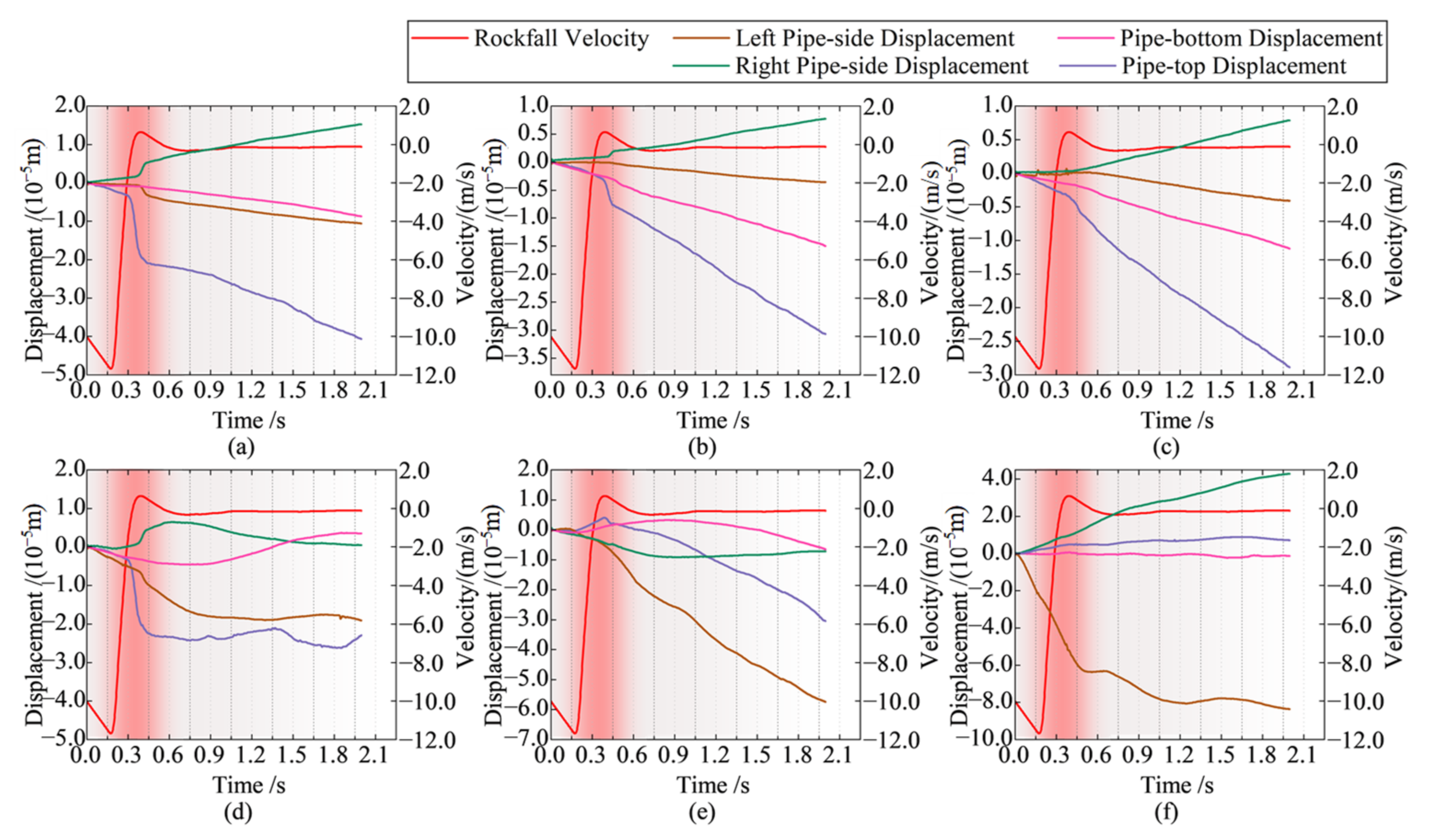
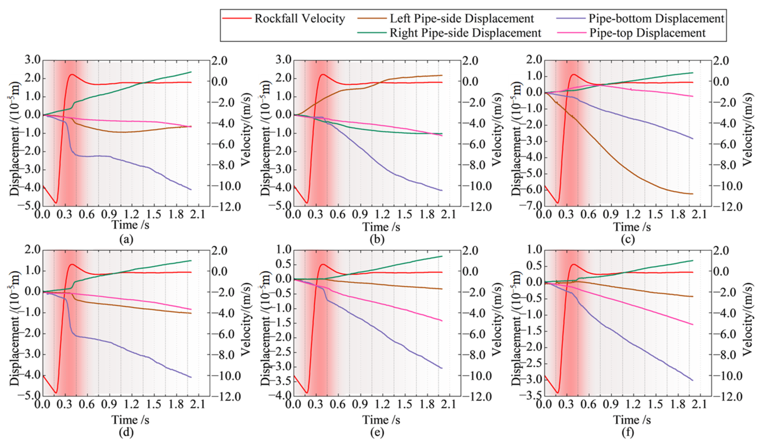
Figure 9 displays the time displacement changes in the positions of the midspan and joint of the concrete core and the mortar coating of the left PCCP. Figure 10 shows the time history of displacement changes at the same monitoring position of the cylinder and steel wire. The displacement changes before and after the impact of rockfall are recorded in Table 6. The displacement state of the concrete core, the mortar coating, the steel cylinder in the left PCCP, and the prestressing wire changed rapidly in a short time when impacted by rockfall. After soil adjustment and gravity settlement, the displacement changes exhibited a slowly increasing trend. The dynamic response temporal and spatial evolution laws of the rockfall and PCCP were as follows.
(1) The movement process of the rockfall impact was as follows. ① When the center of the rockfall was 3.0 m from the backfill land surface, the data were recorded, and the rockfall speed was 9.0 m/s. Subsequently, the falling rocks fell freely, the falling speed continued to increase, and the rockfall speed reached a maximum before touching the ground after approximately 11.7 m/s. ② After the falling rock contacted the backfill, its speed rapidly decreased to approximately 0.0 m/s within 0.2 s. ③ The falling rock fell again while its vertical downwards speed increased, and finally decreased to 0.0 m/s after falling and coming into contact with the backfill soil under gravity. ④ The red gradient in the figure represents the core time period of the entire impact, and the duration of the entire impact process did not exceed 0.3 s. It can be seen that the impact of the rockfall on the buried pipeline was a clear dynamic process.
(2) The temporal progression of displacement variations in the prestressed concrete cylinder pipe (PCCP) across its pipe-top, pipe-side, and pipe-bottom cross-sections unfolded as follows. ① As shown in Figure 9a–e, the displacement of the concrete core and steel cylinder at the pipe-top significantly increased, and the displacement change at the pipe-top surpassed 2.5 × 10⁻⁵ m within 1.5 s, irrespective of the midspan or joint position, which significantly surpassed the displacements observed at the pipe-side and pipe-bottom cross-sections. ② In reference to the mortar coating, the displacement of the pipe-top at the midspan position (Figure 9d) swiftly ascended to 2.3 × 10⁻⁵ m within 0.2 s, which was slightly greater than the displacement of both pipe-sides, while the displacement of both pipe-sides at the joint position was the largest, as shown in Figure 9e,f. ③ Regarding the prestressing wire, the displacements at the midspan position of the pipe’s apex (Figure 10a) and spigot position (Figure 10b) elevated to 3.1 × 10⁻⁵ m and 3.5 × 10⁻⁵ m within 1.5 s, respectively, surpassing the displacements at other positions. Concurrently, the displacement of the left pipe-side of the socket surged to 5.8 × 10⁻⁵ m within 1.5 s, a change significantly exceeding other sections at various positions of the mortar coating. Consequently, excluding the mortar coating at the joint position and the wire at the socket position, materials at other positions illustrated that the maximum displacement transpired in the pipe-top section.
(3) The spatial evolution of the displacement changes in the cross-sections of the pipe-top, pipe-side, and pipe-bottom of the PCCP can be described as follows. When subjected to rockfall, the top of the pipe was impacted, and settlement deformation occurred. The two sides of the pipe were squeezed out under pressure, and a certain settlement deformation also appeared at the bottom. This deformation was consistent with empirical observations. There were differences in the spatial distributions of displacements at the positions of individual materials, which may have been due to the complex multi-layer material structure of the PCCP. As the interaction relationship and influence degree were complex, the deformation relationship and amount may have been different.
(4) The evolution of displacement changes of the PCCP’s spigot, socket, and midspan position could be described as follows. As shown in Figure 9a,d and Figure 10a,d, a significant and abrupt displacement was observed in the midspan position, particularly evident at the pipe-top cross-section upon the rockfall impact. This phenomenon could be attributed to the direct impact of the rockfall at the mid-span position. Furthermore, materials located at the joint position primarily manifested gradual changes in displacement, largely attributable to ongoing adjustments of the soil and pipeline following the impact of the rockfall.
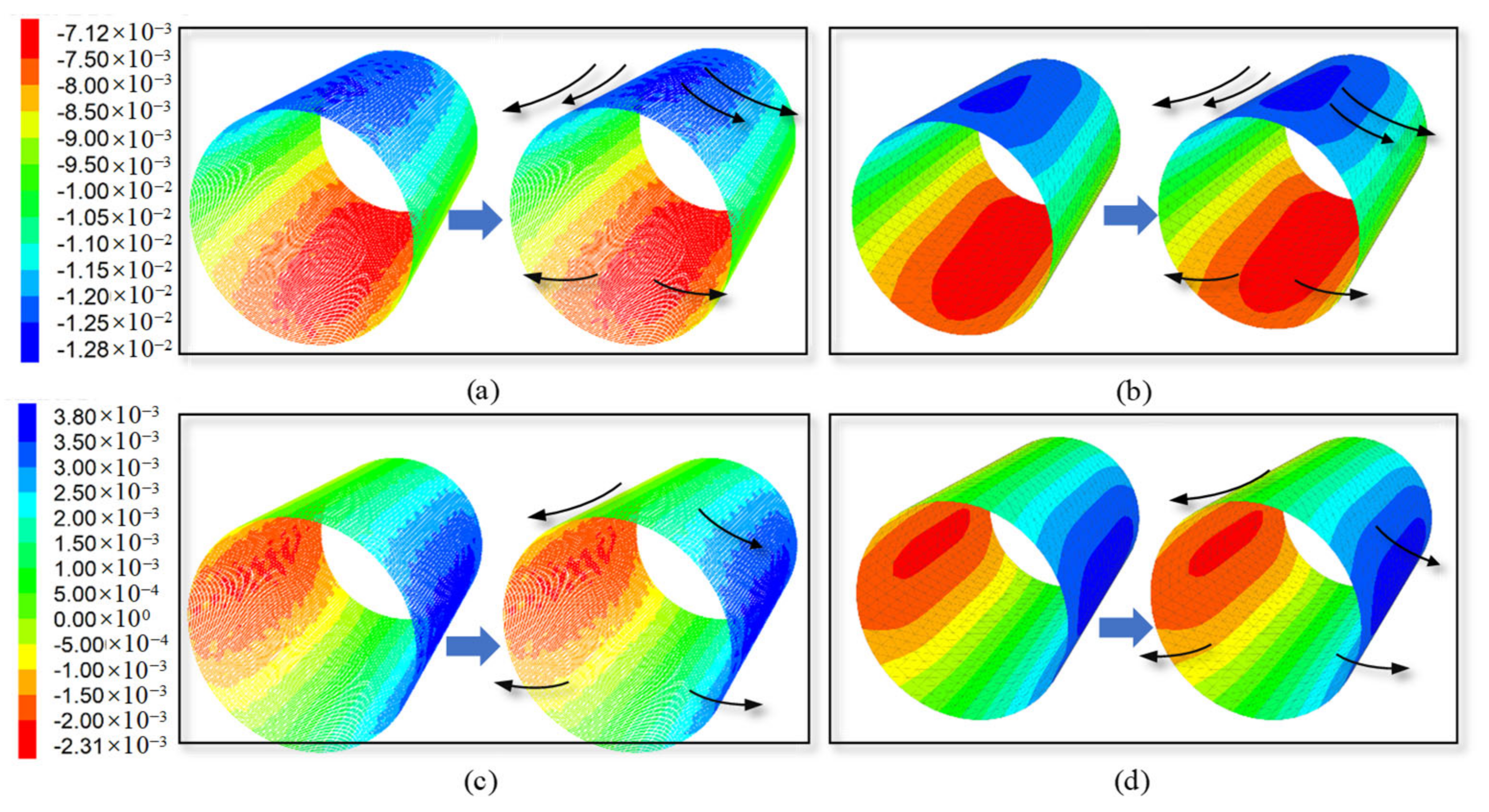
The spatial distributions of vertical and horizontal displacements of the left PCCP prestressing wire and steel cylinder before and after the rockfall impact are shown in Figure 11. The black arrows represent the direction of the displacement trend. ① First, the vertical displacement of the wire and steel cylinder was larger at the cross-section of the pipe-top and pipe-bottom at the midspan position, and smaller at other monitoring locations. Similarly, the horizontal displacement was larger on both sides of the cross-section of the pipe at the midspan position, and smaller at other monitoring locations. The horizontal displacement was greater on both sides of the cross-section of the pipe at the midspan position, and smaller at other monitoring locations. Under static loads and dynamic impact loads, the vertical deformations of the steel cylinder and prestressing wire of the PCCP were identical and demonstrated a central flattening trend. ② The affected area in the vertical direction of the pipe-top of the prestressing wire and steel cylinder at the midspan position was significantly expanded, as shown in Figure 10, and the vertical downwards displacement of the pipe-top area further increased. The horizontal change in each monitoring location of prestressing wire and steel cylinder was small, which indicated that the impact of falling rock had the most obvious effect on the vertical displacement of the cross-section of the pipe-top at the midspan position of the pipeline.
Based on the analysis above, it was evident that the impact load increased the deformation of every monitored component. Notably, the deformation of the pipe-top at the midspan of the concrete core, the pipe-side at the spigot position of the mortar coating, the pipe-top at the midspan of the steel cylinder, and the pipe-top at the midspan of the wire underwent significant changes. These changes could potentially result in damage, and thus warrant careful consideration of these characteristic positions in future design and monitoring efforts.

5. Effects of Rockfall Parameters on the Response of a PCCP

5.1. Impact of Rockfall Radius on PCCP Response

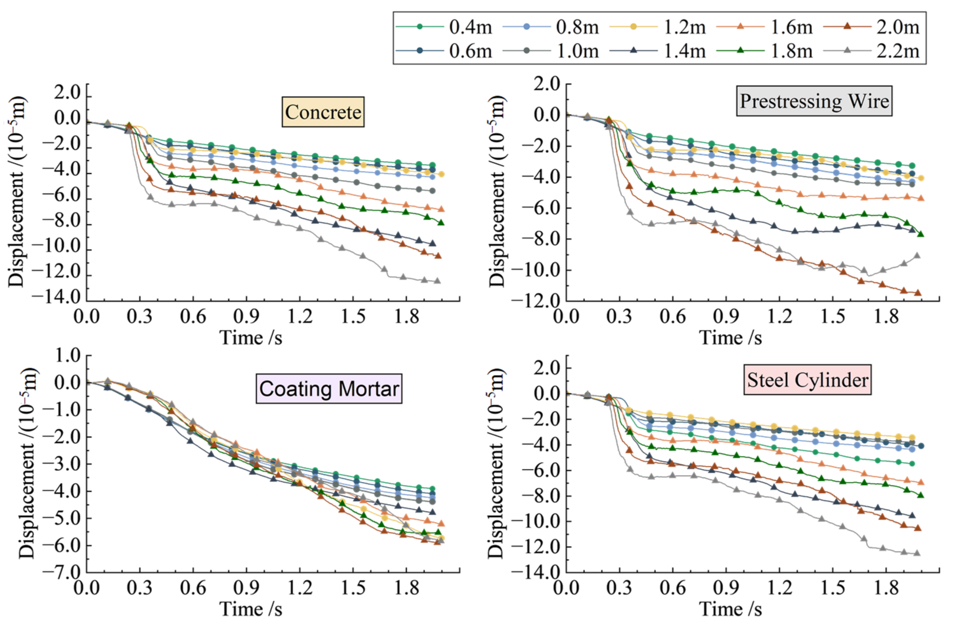
To study the impact of the rockfall radius on changes in the displacement of a PCCP, a rockfall with a density of 2500 kg/m3 was set to fall vertically from a suspension height of 8 m directly above the second buried pipeline on the left. Conditions 1 to 10 were selected for the dynamic response analysis, with rockfall radii of 0.4 m, 0.6 m, 0.8 m, 1.0 m, 1.2 m, 1.4 m, 1.6 m, 1.8 m, 2.0 m, and 2.2 m, respectively. The time evolution of the displacement changes and their relationship with the rockfall radius at the key position were obtained, and are shown in Figure 12.
By analyzing the displacement time history at different material characteristic positions under various rockfall radii, the following conclusions can be obtained from Figure 12: ① When subjected to rockfalls with different radii, the displacement of the concrete core, steel cylinder, and prestressing wire at the pipe-top-midspan of the PCCP all underwent significant changes. Additionally, as the radius of the rockfall increased, the displacement of the concrete core, steel cylinder, and prestressing wire at the pipe-top-midspan position showed a marked increase. ② The displacement of the mortar coating at both pipe-sides remained consistently stable and showed no significant displacement gaps, even as the rockfall radius increased. Obviously, the displacement changes in the mortar coating at both sides of the pipe exhibited a weak correlation with the radius.
Figure 13 shows the analysis of the displacement–radius relationship at the final moment of each material characteristic position under different rockfall radii. The conclusions were as follows: ① As the radius increased, the displacement at both sides of the pipe cross-section in the spigot position of the mortar coating basically remained unchanged. The displacement of the monitoring points at the pipe-top in the midspan position of the concrete core, steel cylinder, and wire increased with the increasing radius in the vertical negative direction. ② When the radius of the rockfall was less than 1.2 m, the displacement difference between the monitoring locations was small. When the radius of the rockfall was greater than 1.2 m, the displacement difference gradually increased as the radius increased. ③ For the pipe-top of the concrete core, steel cylinder, and wire, when the rockfall radius reached 1.2 m, the displacement underwent a small, sudden change and decreased along the negative direction. When the radius of the rockfall reached 1.4 m, the displacement suddenly increased along the negative direction. When the rockfall radius reached 1.6 m, the displacement decreased in the vertical negative direction. The displacement value was close to the 1.0 m rockfall radius, and then increased with the increasing rockfall radius.

5.2. Impact of Rockfall Height on PCCP Response

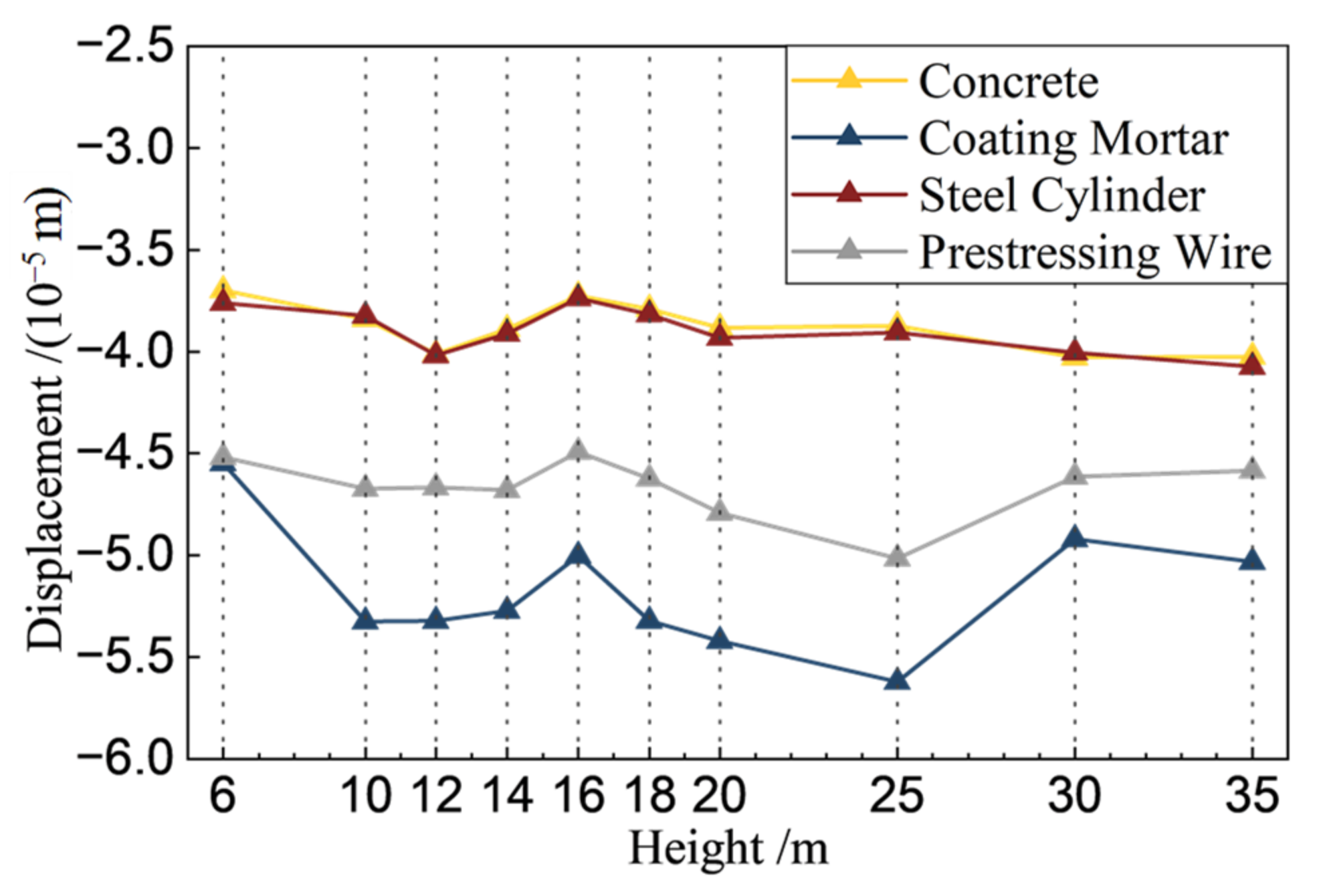
Rockfall and collapse disasters at various heights may occur along a pipeline. In this study, the displacement changes in the characteristic positions of PCCP materials under different working conditions were compared to study the impact force of rockfall at different heights. In this analysis, it was assumed that a spherical rockfall with a radius of 1.2 m would fall directly above the left PCCP and vertically impact the backfill at the top of the pipe. Conditions 10 to 20 were designated, with suspended rockfall heights set at 6 m, 10 m, 12 m, 14 m, 16 m, 18 m, 20 m, 25 m, 30 m, and 35 m, respectively. Regardless of air resistance, when the rockfall was 3 m from the backfill, the timing started, and the rockfall speeds at this position for each condition were 7.8 m/s, 11.8 m/s, 13.4 m/s, 14.8 m/s, 16.1 m/s, 17.2 m/s, 18.3 m/s, 20.8 m/s, 23.1 m/s, and 25.1 m/s, respectively. The deformation curves of different parts with the heights of the rockfalls are shown in Figure 14 and Figure 15.
The conclusions drawn from Figure 14 are as follows. ① The impact of rockfalls from varying heights on the PCCP, the pipe-top-midspan position of the concrete core, steel cylinder, and wire resulted in significant abrupt changes in displacement within 0.1 s. However, the displacement of the pipe-side-midspan position of the mortar coating showed a relatively stable overall trend. This may be attributed to the fact that the pipe-side cross-section was close to the coupling boundary entity unit and squeezed by the entity unit, which led to negligible changes in its displacement. ② Analysis of Figure 14 reveals that the displacement at each monitoring point did not exhibit any noticeable variation with the increasing rockfall height.
The following conclusions can be drawn from Figure 15: ① With the increasing rockfall height, the change in the displacement of the characteristic position increased slightly. Nevertheless, the displacement change was minimal, suggesting a weak correlation between the displacement alteration of the PCCP post-impact and the height of the rockfall. Moreover, the variation in rockfall height exhibited minimal impact on the PCCP. ② The influence of rockfall impact on displacement was greater at the positions of the pipe-top-midspan of the concrete core and prestressing wire than the joint of the mortar coating or the pipe-top-midspan of the steel cylinder.

6. Discussion

To focus on the problem of rockfall impact on a PCCP, a continuous–discontinuous “Pipe-Soil-Rock” model was developed to investigate the spatiotemporal progression of displacements of PCCP components subsequent to a rockfall. The key findings of the analysis were as follows.
(1) A continuous–discontinuous “Pipe-Soil-Rock” model was constructed that could effectively consider the characteristics of various materials and fully consider the problems of large deformations and discontinuous media such as material sliding, backfill crushing, and swelling during rockfall impact. This approach enabled the analysis of soil–pipe contact from the perspective of granular materials, facilitating a more efficient calculation of the mechanical response of PCCP and a simulation process closely resembling engineering practice.
(2) The response of a PCCP to a rockfall impact was a dynamic process, and each material at the midspan position showed a large, abrupt displacement under rockfall impact. The deformations of the pipe-top-midspan position of the concrete core, both pipe-sides at the joint position of the mortar coating, and the pipe-top-midspan position of the steel cylinder and the wire changed greatly, while the pipeline as a whole also showed a trend of central flattening. Additionally, these parts were vulnerable to damage.
(3) The displacement change in the PCCP after impact was weakly correlated with the height of the rockfall, but it continued to increase with the increasing rockfall radius. Therefore, in the actual project of interest in this study, the pipeline should be rerouted to avoid traversing areas of high susceptibility. Alternatively, the deployment of protective netting may be deemed necessary to minimize the degree of harm from rockfalls.
(4) At present, there have been studies on pipelines impacted by rockfalls, but most of the studied pipelines have been oil and gas steel pipes with relatively simple structures, and there are few studies on the related dynamics of pipelines with multi-layer materials and complex structures, such as PCCPs. Compared with similar studies on steel tubes affected by falling rock, it is significant to use the continuous–discontinuous method to simulate the soil deformation and impact process under the impact of falling rock. It can accurately reflect the transient process of rockfall impact, and rockfall impact, rebound, and soil deformation can be accurately reflected in the simulation.
(5) Compared with the traditional continuous numerical simulation method used to simulate the impact of rockfalls on PCCP pipelines, the deformation of PCCPs is roughly the same as the strain of each part. Each material of PCCP had its own vulnerable parts, and the entire material showed a trend of center flattening. At the same time, this paper used a discontinuous numerical simulation method to simulate rockfalls and backfill soil, which can more clearly and directly show the particle influence state of rockfall’s impact on backfill soil.
(6) In summary, the continuous–discontinuous numerical simulation method in the simulation of rockfall’s impact on PCCP pipes, uses the continuous numerical model to simulate PCCPs and uses the discontinuous numerical model to simulate backfill and rockfall, combining the advantages of both and accurately reflecting the deformation of soil and PCCPs. This method has strong research value.

Author Contributions

Writing—original draft, Y.T.; writing—review and editing, C.M. and Y.Z.; resources, C.M., J.Y. and L.C.; data curation, C.M., J.Y. and L.C. All authors have read and agreed to the published version of the manuscript.

Funding

This research was funded by the National Natural Science Foundation of China (Grant No. 52279140); the Innovation Capability Support Program of Shaanxi (Grant No. 2024CX-GXPT-23) the Natural Science Basic Research Program of Shaanxi (Grant No. 2023-JC-QN-0562); the Scientific Research Program Funded by Shaanxi Provincial Education Department (Grant No. 23JY058).

Data Availability Statement

The raw data supporting the conclusions of this article will be made available by the authors on request.

Conflicts of Interest

Author Yonglin Zhou was employed by the company Northwest Engineering Corporation Limited. The remaining authors declare that the research was conducted in the absence of any commercial or financial relationships that could be construed as a potential conflict of interest.

References

  1. AWWA C304-92; AWWA Standard for Design of Prestressed Concrete Cylinder Pipe. AWWA: Denver, CO, USA, 1993.
  2. Zarghamee, M.S.; Moharrami, M. Experimental Study and Numerical Simulation of Three-Edge Bearing Test of Large Diameter Prestressed Concrete Cylinder Pipes. In Proceedings of the Pipelines 2018 American Society of Civil Engineers, Toronto, ON, Canada, 12 July 2018; pp. 776–787. [Google Scholar]
  3. Zhang, Y.; Yan, Z.; Zhu, H.; Ju, J.W. Experimental Study on the Structural Behaviors of Jacking Prestressed Concrete Cylinder Pipe. Tunn. Undergr. Space Technol. 2018, 73, 60–70. [Google Scholar] [CrossRef]
  4. Ge, S.; Sinha, S. Failure Analysis, Condition Assessment Technologies, and Performance Prediction of Prestressed-Concrete Cylinder Pipe: State-of-the-Art Literature Review. J. Perform. Constr. Facil. 2014, 28, 618–628. [Google Scholar] [CrossRef]
  5. Hu, S. Study on structural safety evaluating technique for pre-stressed concrete cylinder pipe (PCCP) in the South-to-North Water Diversion Project. Hydro-Sci. Eng. 2009, 4, 74–82. [Google Scholar] [CrossRef]
  6. Yu, L.; Zhao, X.; Hu, S.; Lu, J.; Lu, W. Finite element analysis study on pipeline pressure of PCCP in service based on ABAQUS. Concrete 2015, 135–138. [Google Scholar] [CrossRef]
  7. Xiong, H.; Li, P.; Li, Q. FE Model for Simulating Wire-Wrapping during Prestressing of an Embedded Prestressed Concrete Cylinder Pipe. Simul. Model. Pract. Theory 2010, 18, 624–636. [Google Scholar] [CrossRef]
  8. Gomez, H.; Garrido, A.; Arrondo, J.I.; Falcinelli, S. Fracturas Laterales de Cadera. 100 Primeros Casos Utilizando Sistema de Estabilización PCCP. Rev. Asoc. Arg. Ort. Traumatol. 2016, 81, 206. [Google Scholar] [CrossRef]
  9. Hajali, M.; Alavinasab, A.; Abi Shdid, C. Structural Performance of Buried Prestressed Concrete Cylinder Pipes with Harnessed Joints Interaction Using Numerical Modeling. Tunn. Undergr. Space Technol. 2016, 51, 11–19. [Google Scholar] [CrossRef]
  10. Ge, S.; Sinha, S. Effect of Mortar Coating’s Bond Quality on the Structural Integrity of Prestressed Concrete Cylinder Pipe with Broken Wires. JMSR 2015, 4, 59. [Google Scholar] [CrossRef]
  11. Mao, H.; Chen, L.; Yang, J.; Ma, C.; Yuan, X. Stress-strain response of buried PCCP under rockfall impact load. J. Yangtze River Sci. Res. Inst. 2022, 39, 113–119. [Google Scholar]
  12. Khosrozadeh, A.; Hashemnia, K.; Vatankhah, R. Investigating Impact-Induced Vibrations of Fluid-Conveying Elastic Pipes Considering Hertz Theory. Mech. Res. Commun. 2021, 116, 103762. [Google Scholar] [CrossRef]
  13. Thornton, C.; Ning, Z. A Theoretical Model for the Stick/Bounce Behaviour of Adhesive, Elastic-Plastic Spheres. Powder Technol. 1998, 99, 154–162. [Google Scholar] [CrossRef]
  14. Muleski, G.E.; Ariman, T.; Aumen, C.P. A Shell Model of a Buried Pipe in a Seismic Environment. J. Press. Vessel. Technol. 1979, 101, 44–50. [Google Scholar] [CrossRef]
  15. Wang, S. Evaluation of Underground Pipe-Structure Interface for Surface Impact Load. Nucl. Eng. Des. 2017, 317, 59–68. [Google Scholar] [CrossRef]
  16. Tian, J.; Zhang, J.; Dong, F.; Du, G. Dynamic Response of Buried Pipeline Subject to Impact Loads Using Piezoceramic Transducers. Int. J. Press. Vessel. Pip. 2019, 177, 103984. [Google Scholar] [CrossRef]
  17. Zhang, J.; Liang, Z.; Han, C.; Zhang, H. Buckling Behaviour Analysis of a Buried Steel Pipeline in Rock Stratum Impacted by a Rockfall. Eng. Fail. Anal. 2015, 58, 281–294. [Google Scholar] [CrossRef]
  18. Zhang, J.; Liang, Z.; Feng, D.; Zhang, C.; Xia, C.; Tu, Y. Response of the Buried Steel Pipeline Caused by Perilous Rock Impact: Parametric Study. J. Loss Prev. Process Ind. 2016, 43, 385–396. [Google Scholar] [CrossRef]
  19. Xiong, J.; Deng, Q.; Zhang, H.; Pang, W. Safety Assessment on the Response of Buried Pipeline Caused by Rockfall Impact Load. Saf. Environ. Eng. 2013, 20, 108–114. [Google Scholar]
  20. Tavakoli Mehrjardi, G.; Karimi, M. Numerical Modeling of Buried Steel Pipe Subjected to Impact Load. J. Pipeline Syst. Eng. Pract. 2021, 12, 04021048. [Google Scholar] [CrossRef]
  21. Leine, R.I.; Schweizer, A.; Christen, M.; Glover, J.; Bartelt, P.; Gerber, W. Simulation of Rockfall Trajectories with Consideration of Rock Shape. Multibody Syst. Dyn. 2014, 32, 241–271. [Google Scholar] [CrossRef]
  22. Liu, M.; Yang, M. Modeling the Behavior of Natural Gas Pipeline Impacted by Falling Objects. Eng. Fail. Anal. 2014, 42, 45–59. [Google Scholar] [CrossRef]
  23. Deng, X.; Xue, S.; Tong, X. Numerical simulation on response of buried pipeline induced by rock-fall transverse impaction. J. China Univ. Pet. (Ed. Nat. Sci.) 2009, 33, 111–115+120. [Google Scholar]
  24. Huang, W. Study on Rockfall Motion Characteristics and Dynamic Response of Shed Cave-Wall Based on Coupling of PFC~ (3D) and FLAC~ (3D). Master’s Thesis, Southwest Jiaotong University, Chengdu, China, 2022. [Google Scholar]
  25. Wang, D.; Liu, H.; Pe, X.; Sun, X.; Zhou, L.; Liu, Y. Study on dynamic response of cushion layer of rolling stone impact tunnel based on discrete element-finite difference coupling. Vib. Shock. 2021, 40, 246–253. [Google Scholar]
  26. Hou, C.; Cheng, Y.; Li, Y.; Sun, Z.; Jiang, X. Simulation and analysis of load loading process of buried pipeline based on discrete-continuous coupling method. J. Hefei Univ. Technol. (Nat. Sci. Ed.) 2023, 46, 96–103. [Google Scholar]
  27. Huang, K.; Sun, Y.; Chen, X.; Deng, X.; Liu, R.; Wu, Q. Study on three-dimensional displacement characteristics of earth mass before shield excavation based on FDM-DEM coupling. China Highw. J. 2023, 36, 190–206. [Google Scholar] [CrossRef]
  28. Tu, Y.; Chen, X.; Wang, X.; Chai, H.; Zhang, L.; Zhang, R. Slope stability analysis based on continuous-discrete coupling strength reduction method. Eng. Mech. 2023, 40, 1–12. [Google Scholar]
  29. Cheng, B.; Dou, T.; Xia, S.; Zhao, L.; Yang, J.; Zhang, Q. Experimental Study on Mechanical Properties of Prestressed Concrete Cylinder Pipes (PCCPs) under External Load. Int. J. Press. Vessel. Pip. 2021, 191, 104365. [Google Scholar] [CrossRef]
  30. Cheng, B.; Dou, T.; Xia, S.; Zhao, L.; Yang, J.; Zhang, Q. Mechanical Properties and Loading Response of Prestressed Concrete Cylinder Pipes under Internal Water Pressure. Eng. Struct. 2020, 216, 110674. [Google Scholar] [CrossRef]
  31. Plassiard, J.-P.; Donze, F. Rockfall Impact Parameters on Embankments: A Discrete Element Method Analysis. Struct. Eng. Int. 2009, 19, 333–341. [Google Scholar] [CrossRef]
  32. Zheng, L.; Wu, Y.; Wu, W.; Zhang, H.; Peng, X.; Zhang, X.; Wu, X. Efficient Investigation of Rock Crack Propagation and Fracture Behaviors during Impact Fragmentation in Rockfalls Using Parallel DDA. Adv. Civ. Eng. 2021, 2021, 5901561. [Google Scholar] [CrossRef]
  33. Bertrand, D.; Trad, A.; Limam, A.; Silvani, C. Full-Scale Dynamic Analysis of an Innovative Rockfall Fence Under Impact Using the Discrete Element Method: From the Local Scale to the Structure Scale. Rock Mech. Rock Eng. 2012, 45, 885–900. [Google Scholar] [CrossRef]
  34. Cheng, Y.P.; Nakata, Y.; Bolton, M.D. Discrete Element Simulation of Crushable Soil. Géotechnique 2003, 53, 633–641. [Google Scholar] [CrossRef]
  35. Shiu, W.-J.; Lee, C.-F.; Chiu, C.-C.; Weng, M.-C.; Yang, C.-M.; Chao, W.-A.; Liu, C.-Y.; Lin, C.-H.; Huang, W.-K. GeoPORT Working Group Analyzing Landslide-Induced Debris Flow and Flow-Bridge Interaction by Using a Hybrid Model of Depth-Averaged Model and Discrete Element Method. Landslides 2022, 20, 331–349. [Google Scholar] [CrossRef]
  36. Cundall, P.A.; Strack, O.D.L. A Discrete Numerical Model for Granular Assemblies. Géotechnique 1979, 29, 47–65. [Google Scholar] [CrossRef]
  37. Ding, X.; Zhang, L.; Zhu, H.; Zhang, Q. Effect of Model Scale and Particle Size Distribution on PFC3D Simulation Results. Rock Mech. Rock Eng. 2014, 47, 2139–2156. [Google Scholar] [CrossRef]
  38. Naito, N.; Maeda, K.; Konno, H.; Ushiwatari, Y.; Kawase, R. Rockfall Impacts on Sand Cushions with Different Soil Mechanical Characteristics Using Discrete Element Method. Soils Found 2020, 60, 384–397. [Google Scholar] [CrossRef]
  39. Yuan, S.; Zhao, P.; Li, L.; Wang, X.; Liu, J.; Zhang, B. A Discrete Numerical Study of the Effect of the Thickness and the Porosity of the Sand Cushion on the Impact Response Due to the Rockfall. CMES-Comp. Model. Eng. Sci. 2022, 130, 1683–1698. [Google Scholar] [CrossRef]
  40. Guzev, M.A. Non-Classical Solutions of a Continuum Model for Rock Descriptions. J. Rock Mech. Geotech. Eng. 2014, 6, 180–185. [Google Scholar] [CrossRef]
  41. Madhavi Latha, G.; Garaga, A. Elasto-Plastic Analysis of Jointed Rocks Using Discrete Continuum and Equivalent Continuum Approaches. Int. J. Rock Mech. Min. Sci. 2012, 53, 56–63. [Google Scholar] [CrossRef]
  42. Breugnot, A.; Lambert, S.; Villard, P.; Gotteland, P. A Discrete/Continuous Coupled Approach for Modeling Impacts on Cellular Geostructures. Rock Mech. Rock Eng. 2016, 49, 1831–1848. [Google Scholar] [CrossRef]
  43. Wang, Y.S.; Zhang, K.Y.; Tang, J.H.; Liang, D. Model Test Research of the Influences of Rock-Fall Impaction on Accelerations of the Cut-and-Cover Tunnel Structure. AMM 2011, 117–119, 206–211. [Google Scholar] [CrossRef]
  44. Cao, W.; Li, X.; Tao, M.; Zhou, Z. Vibrations Induced by High Initial Stress Release during Underground Excavations. Tunn. Undergr. Space Technol. 2016, 53, 78–95. [Google Scholar] [CrossRef]
  45. Su, Y.; Cui, Y.; Ng, C.; Choi, C.E.; Kwan, J. Effects of Particle Size and Cushioning Thickness on the Performance of Rock-Filled Gabions Used in Protection against Boulder Impact. Can. Geotech. J. 2019, 56, 198–207. [Google Scholar] [CrossRef]
  46. Cai, M.; Kaiser, P.K.; Morioka, H.; Minami, M.; Maejima, T.; Tasaka, Y.; Kurose, H. FLAC/PFC Coupled Numerical Simulation of AE in Large-Scale Underground Excavations. Int. J. Rock Mech. Min. Sci. 2007, 44, 550–564. [Google Scholar] [CrossRef]
  47. Wei, C.; Apel, D.; Katsaga, T. Coupled Finite-Difference and Discrete-Element Method for Modelling Direct Shear Tests on Combined Rock-Cemented Rockfill Specimens. Min. Metall. Explor. 2022, 39, 89–109. [Google Scholar] [CrossRef]
  48. Kawahara, S.; Muro, T. Effects of Dry Density and Thickness of Sandy Soil on Impact Response Due to Rockfall. J. Terramechan 2006, 43, 329–340. [Google Scholar] [CrossRef]
  49. Liu, F.; Tang, C.; Zhang, Y.; Ma, T. Rockburst and Microseismicity Characteristics in the Qinling Water Conveyance Tunnel of the Hanjiang-to-Weihe River Diversion Project. Int. J. Rock Mech. Min. Sci 2021, 148, 104973. [Google Scholar] [CrossRef]
  50. Indraratna, B.; Ngo, N.T.; Rujikiatkamjorn, C.; Sloan, S.W. Coupled Discrete Element–Finite Difference Method for Analysing the Load-Deformation Behaviour of a Single Stone Column in Soft Soil. Comput. Geotech. 2015, 63, 267–278. [Google Scholar] [CrossRef]
  51. Jia, M.; Yang, Y.; Liu, B.; Wu, S. PFC/FLAC Coupled Simulation of Dynamic Compaction in Granular Soils. Granul. Matter 2018, 20, 76. [Google Scholar] [CrossRef]
  52. Liu, G.; Li, J. A Three-Dimensional Discontinuous Deformation Analysis Method for Investigating the Effect of Slope Geometrical Characteristics on Rockfall Behaviors. Int. J. Comput. Methods 2019, 16, 1850122. [Google Scholar] [CrossRef]
  53. Thoeni, K.; Giacomini, A.; Lambert, C. A 3D Discrete Element Modelling Approach for Rockfall Analysis with Drapery Systems. Int. J. Rock Mech. Min. Sci. 2014, 68, 107–119. [Google Scholar] [CrossRef]
  54. Ma, C.; Chen, L.; Yang, K.; Yang, J.; Tu, Y.; Cheng, L. Intelligent Calibration Method for Microscopic Parameters of Soil–rock Mixtures Based on Measured Landslide Accumulation Morphology. Comput. Methods Appl. Mech. Eng. 2024, 422, 116835. [Google Scholar] [CrossRef]
  55. Zhan, R.; Chen, Z.; Zeng, G.; Cheng, X. Development characteristics and prevention suggestions of geological disasters in Danjiangkou Reservoir area. Water Resour. Hydropower Express 2020, 41, 31–36. [Google Scholar] [CrossRef]
  56. Liang, Y.; Niu, F.; Xie, W. Development and distribution law of geological hazards along the Jiwei project in Yanhan, Shaanxi Province. Shaanxi Geol. 2021, 39, 96–102. [Google Scholar]
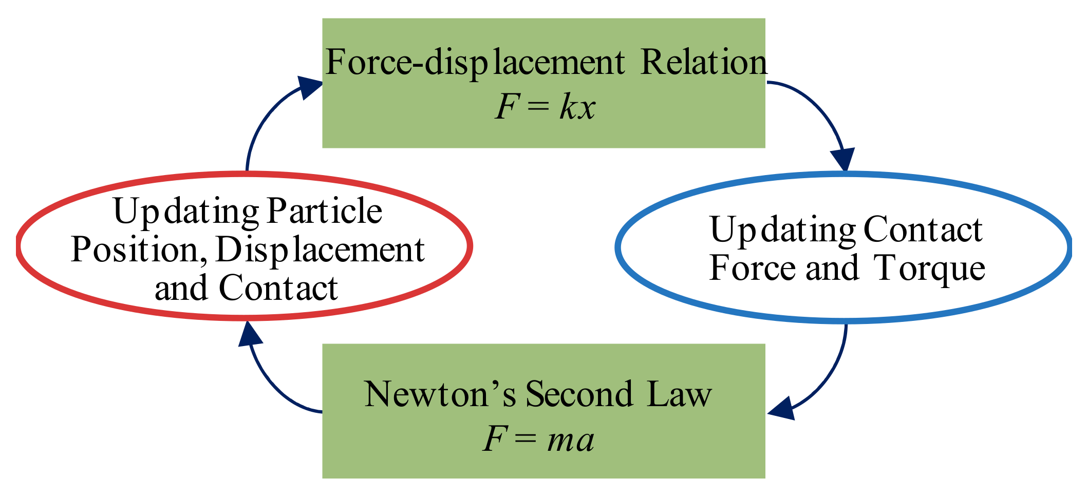
Figure 1. The principle of DEM.
Water 16 00801 g001
Figure 2. Linear contact model.
Water 16 00801 g002
Figure 3. Transmission of continuous–discontinuous coupling boundary force.
Water 16 00801 g003
Figure 4. Continuous–discontinuous coupling boundary.
Water 16 00801 g004
Figure 5. The continuous–discontinuous “Pipe-Soil-Rock” model: (a) the overall model of rockfall’s impact on PCCP, (b) semi-section of the coupling model, and (c) local profile of the coupling model.
Water 16 00801 g005
Figure 6. Construction model of a PCCP based on the FDM.
Water 16 00801 g006
Figure 7. Position coordinate diagram of a rockfall.
Water 16 00801 g007
Figure 8. Ball–pipe contact during an impact process.
Water 16 00801 g008
Figure 9. Displacement time–history curve of concrete and mortar coating under impact loads: (a) concrete–midspan, (b) concrete–spigot joint, (c) concrete–socket joint, (d) coating mortar–midspan, (e) coating mortar–spigot joint, and (f) coating mortar–socket joint.
Water 16 00801 g009
Figure 10. Displacement time–history curve of prestressing wire and steel cylinder under impact loads: (a) prestressing wire–midspan, (b) prestressing wire–spigot joint, (c) prestressing wire–socket joint, (d) steel cylinder–midspan, (e) steel cylinder–spigot joint, and (f) steel cylinder–socket joint.
Water 16 00801 g010
Figure 11. Cloud diagram of the displacement of each PCCP material: (a) the vertical displacement changes in the prestressing wire before and after impact, (b) the vertical displacement changes in the steel cylinder before and after impact, (c) the horizontal displacement changes in the prestressing wire before and after impact, and (d) the horizontal displacement changes in the steel cylinder before and after impact.
Water 16 00801 g011
Figure 12. Displacement time history of each component of the PCCP under rockfall impacts with different radii.
Water 16 00801 g012
Figure 13. The displacement–rockfall radius relationship of each material of the PCCP under rockfall impact.
Water 16 00801 g013
Figure 14. Displacement time history of each component of a PCCP under rockfall impacts from different heights.
Water 16 00801 g014
Figure 15. The displacement–rockfall height relationship of each material of a PCCP under rockfall impacts.
Water 16 00801 g015
Table 1. Parameter table of soil model based on the FDM.
PartDensity (kg/m3)Elastic Modulus (Pa)Poisson’s Ratio
Foundation17704 × 1070.3
Cushion17704 × 1070.3
Backfill20001.055 × 1070.3
Table 2. Parameters of the discontinuous soil model.
MaterialsPoisson’s RatioRadius (m)Damp
Cushion0.30.12~0.150.7
Backfill0.30.18~0.200.7
Table 3. Contact model parameters based on the DEM.
ProjectContact ModelEmod (Pa)Kratiopb_ten (Pa)pb_coh (Pa)
Rockfall–backfillLinear contact model1.055 × 1071.0\\
Cushion–cushionLinear contact model4 × 1061.0\\
Backfill–backfillLinear contact model1.055 × 1071.0\\
Cushion–wallParallel contact model4 × 1071.01 × 101001 × 10100
Backfill–wallParallel contact model1.055 × 1081.01 × 101001 × 10100
Table 4. Material parameters of different layers of the PCCP model.
MaterialsElasticity Modulus
(MPa)
Strength of Extension
(MPa)
Compressive Strength
(MPa)
Density
(kg/m3)
Thickness
(mm)
Prestressing wire205,00015701570783310.39 (diameter)
Steel cylinder206,00023523578331.5
Concrete core35,50035.52.742500300
Mortar coating24,165453.49220040
Spigot steel ring206,000235235783320
Socket steel ring206,000235235783310
Table 5. Rockfall parameter conditions.
ConditionRadius (m)Height (m)ConditionRadius (m)Height (m)
10.48.0111.26
20.68.0121.210
30.88.0131.212
41.08.0141.214
51.28.0151.216
61.48.0161.218
71.68.0171.220
81.88.0181.225
928.0191.230
102.28.0201.235
Table 6. Displacement changes before and after impact (unit: 10−5 m).
Section PositionLeft Pipe-SideRight Pipe-SidePipe-TopPipe-Bottom
Material Location
ConcreteMidspan0.066690.172841.601320.01144
Spigot joint0.003560.017710.172100.05368
Socket joint0.053100.006851.247740.03417
Coating mortarMidspan0.189730.203501.694770.05670
Spigot joint0.243150.160590.192370.13048
Socket joint1.463150.217600.087690.12013
Prestressing wireMidspan0.107030.178741.619420.03652
Spigot joint0.257200.125010.025630.01008
Socket joint0.363390.025680.065760.12159
Steel cylinderMidspan0.028970.012740.135220.05012
Spigot joint0.000580.002390.128040.04947
Socket joint0.095840.126521.619590.00708
Disclaimer/Publisher’s Note: The statements, opinions and data contained in all publications are solely those of the individual author(s) and contributor(s) and not of MDPI and/or the editor(s). MDPI and/or the editor(s) disclaim responsibility for any injury to people or property resulting from any ideas, methods, instructions or products referred to in the content.